- INSTRUCTION DEFINITIONS

Содержание
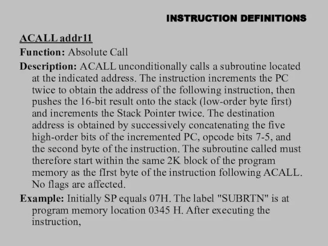
- 2. INSTRUCTION DEFINITIONS ACALL addr11 Function: Absolute Call Description: ACALL unconditionally calls a subroutine located at the
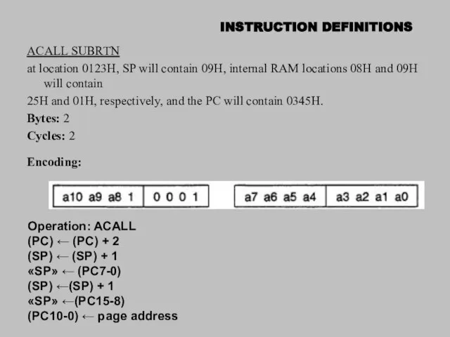
- 3. INSTRUCTION DEFINITIONS ACALL SUBRTN at location 0123H, SP will contain 09H, internal RAM locations 08H and
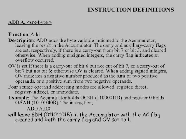
- 4. INSTRUCTION DEFINITIONS ADD A, Function: Add Description: ADD adds the byte variable indicated to the Accumulator,
- 5. INSTRUCTION DEFINITIONS ADD A,Rn Bytes: 1 Cycles: 1 Encoding: Operation: ADD ← (A) + (Rn) ADD
- 6. INSTRUCTION DEFINITIONS ADDC A, Function: Add with Carry Description: ADDC simultaneously adds the byte variable indicated,
- 7. INSTRUCTION DEFINITIONS ADDC A,Rn Bytes: 1 Cycles: 1 Encoding Operation: ADDC (A)← (A) + (C) +
- 8. INSTRUCTION DEFINITIONS ADDC A,@Ri Bytes: 1 Cycles: 1 Encoding: Operation: ADDC ← (A) + (C) +(RJ)
- 9. INSTRUCTION DEFINITIONS AJMP addr11 Function: Absolute Jump Description: AJMP transfers program execution to the indicated address,
- 10. INSTRUCTION DEFINITIONS ANL , Function: Logical-AND for byte variables Description: ANL performs the bitwise logical-AND operation
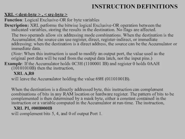
- 11. INSTRUCTION DEFINITIONS ANL P1, #01110011B will clear bits 7, 3, and 2 of output port 1.
- 12. INSTRUCTION DEFINITIONS ANL A,@Ri Bytes: 1 Cycles: 1 Encoding: Operation: ANL (A) ← (A) ∧((Ri)) ANL
- 13. INSTRUCTION DEFINITIONS ANL direct,A Bytes: 2 Cycles: 1 Encoding: Operation: ANL (direct) ← (direct) ∧ (A)
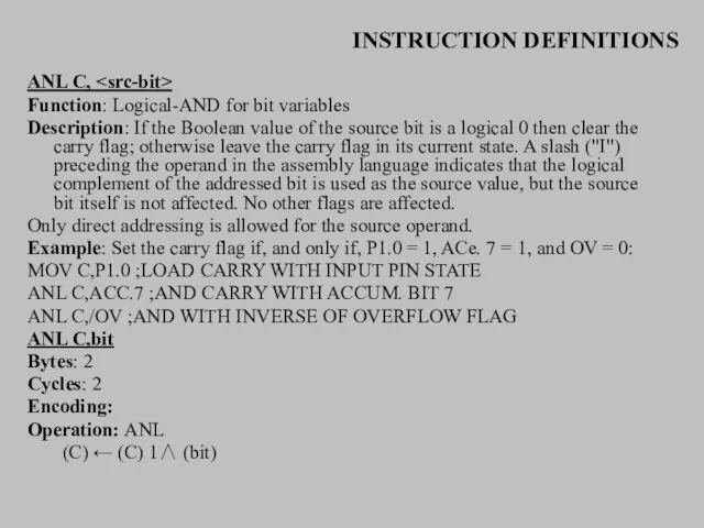
- 14. INSTRUCTION DEFINITIONS ANL C, Function: Logical-AND for bit variables Description: If the Boolean value of the
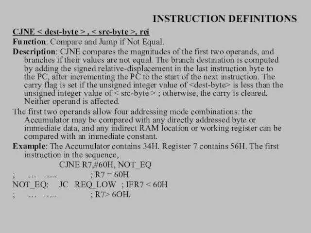
- 15. INSTRUCTION DEFINITIONS CJNE , , rei Function: Compare and Jump if Not Equal. Description: CJNE compares
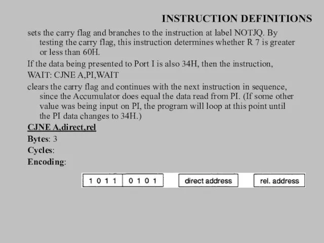
- 16. INSTRUCTION DEFINITIONS sets the carry flag and branches to the instruction at label NOTJQ. By testing
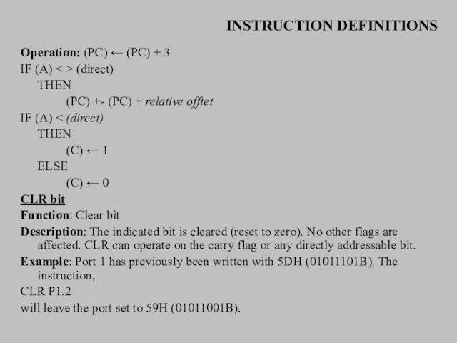
- 17. INSTRUCTION DEFINITIONS Operation: (PC) ← (PC) + 3 IF (A) (direct) THEN (PC) +- (PC) +
- 18. INSTRUCTION DEFINITIONS CPL bit Function: Complement bit Description: The bit variable specified is complemented. A bit
- 19. INSTRUCTION DEFINITIONS If the carry flag is now set, or if the four high-order bits now
- 20. INSTRUCTION DEFINITIONS will first perform a standard twos-complement binary addition, resulting in the value OBEH (10111110)
- 21. INSTRUCTION DEFINITIONS THEN(A3-0) ← (A3-0) + 6 AND IF [[(A7-4) > 9] V [(C) = 1]]
- 22. INSTRUCTION DEFINITIONS DEC A Bytes: 1 Cycles: 1 Encoding: Operation: DEC (A) ← (A) - 1
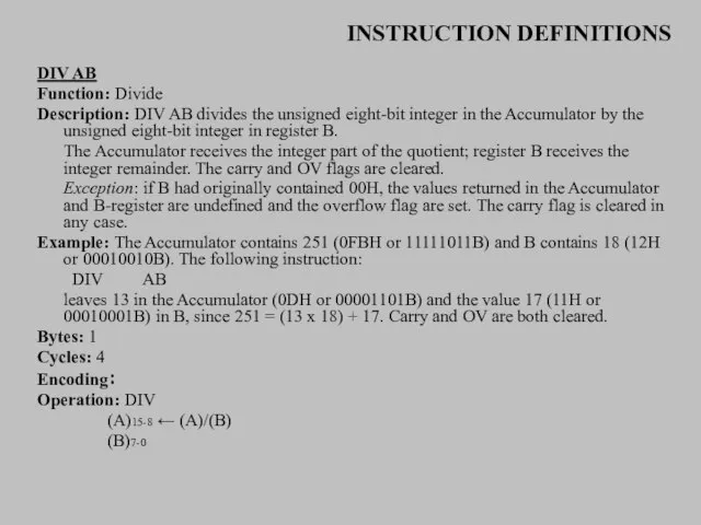
- 23. INSTRUCTION DEFINITIONS DIV AB Function: Divide Description: DIV AB divides the unsigned eight-bit integer in the
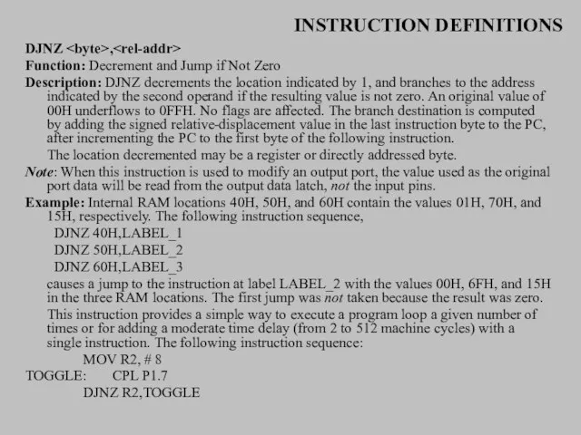
- 24. INSTRUCTION DEFINITIONS DJNZ , Function: Decrement and Jump if Not Zero Description: DJNZ decrements the location
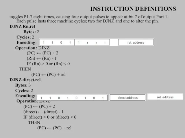
- 25. INSTRUCTION DEFINITIONS toggles P1.7 eight times, causing four output pulses to appear at bit 7 of
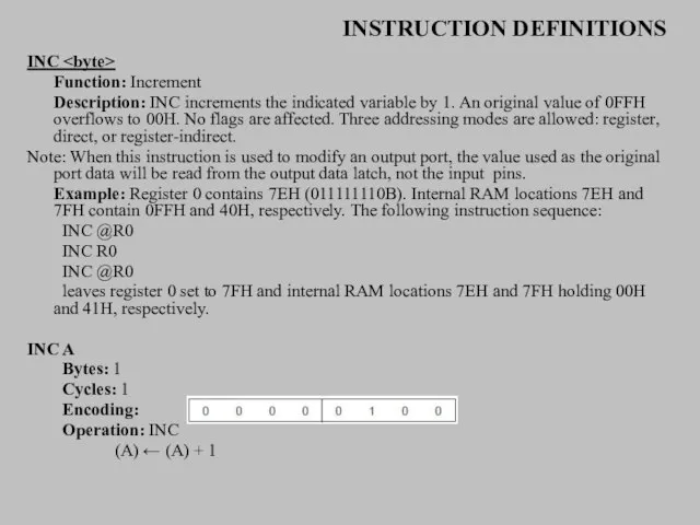
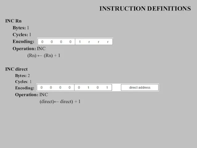
- 26. INSTRUCTION DEFINITIONS INC Function: Increment Description: INC increments the indicated variable by 1. An original value
- 27. INSTRUCTION DEFINITIONS INC Rn Bytes: 1 Cycles: 1 Encoding: Operation: INC (Rn) ← (Rn) + 1
- 28. INSTRUCTION DEFINITIONS INC DPTR Function: Increment Data Pointer Description: INC DPTR increments the 16-bit data pointer
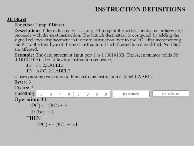
- 29. INSTRUCTION DEFINITIONS JB blt,rel Function: Jump if Bit set Description: If the indicated bit is a
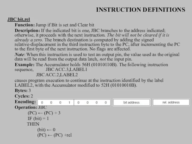
- 30. INSTRUCTION DEFINITIONS JBC bit,rel Function: Jump if Bit is set and Clear bit Description: If the
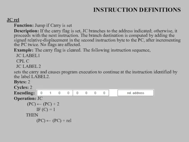
- 31. INSTRUCTION DEFINITIONS JC rel Function: Jump if Carry is set Description: If the carry flag is
- 32. INSTRUCTION DEFINITIONS JMP @A+DPTR Function: Jump indirect Description: Add the eight-bit unsigned contents of the Accumulator
- 33. INSTRUCTION DEFINITIONS Bytes: 1 Cycles: 2 Encoding: Operation: JMP (PC) ~ (A) + (DPTR) JNB bit,rel
- 34. INSTRUCTION DEFINITIONS Operation JNB (PC) ← (PC) + 3 IF (bit) = 0 THEN (PC) ←
- 35. INSTRUCTION DEFINITIONS Bytes: 2 Cycles: 2 Encoding: Operation: LCALL (PC) ← (PC) + 3 (SP) ←(SP)
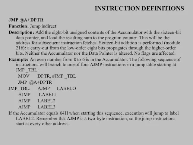
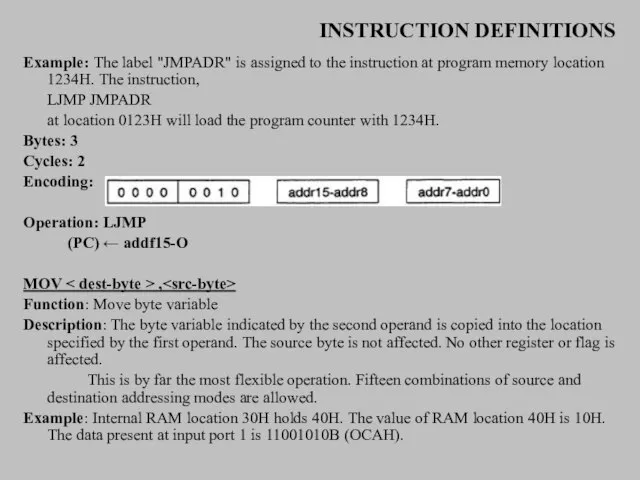
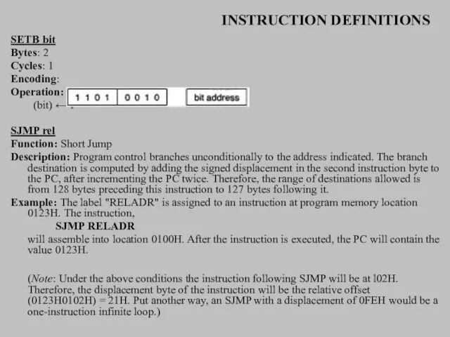
- 36. INSTRUCTION DEFINITIONS Example: The label "JMPADR" is assigned to the instruction at program memory location 1234H.
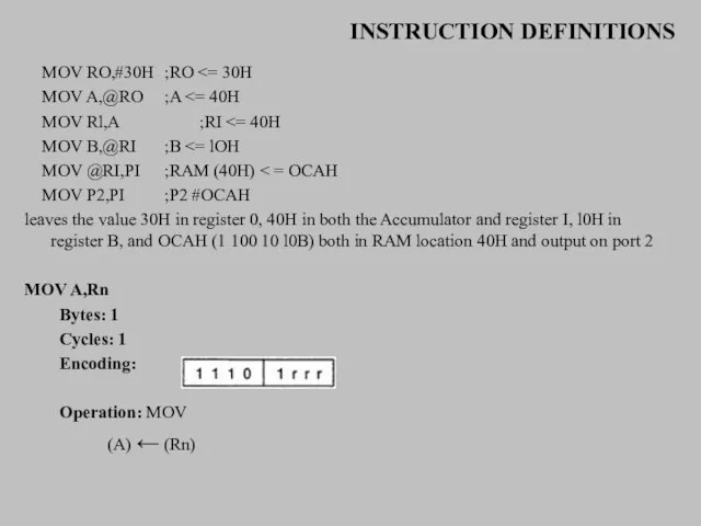
- 37. INSTRUCTION DEFINITIONS MOV RO,#30H ;RO MOV A,@RO ;A MOV Rl,A ;RI MOV B,@RI ;B MOV @RI,PI
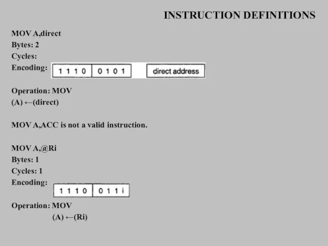
- 38. INSTRUCTION DEFINITIONS MOV A,direct Bytes: 2 Cycles: Encoding: Operation: MOV (A) ←(direct) MOV A,ACC is not
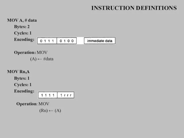
- 39. INSTRUCTION DEFINITIONS MOV A, # data Bytes: 2 Cycles: 1 Encoding: Operation: MOV (A) ← #data
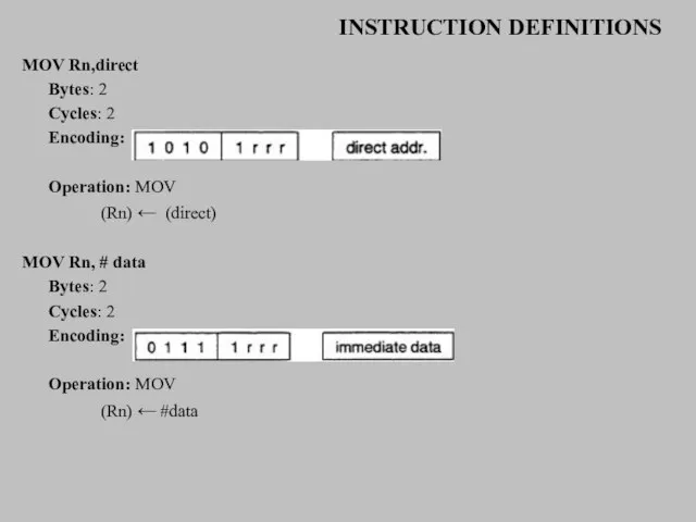
- 40. INSTRUCTION DEFINITIONS MOV Rn,direct Bytes: 2 Cycles: 2 Encoding: Operation: MOV (Rn) ← (direct) MOV Rn,
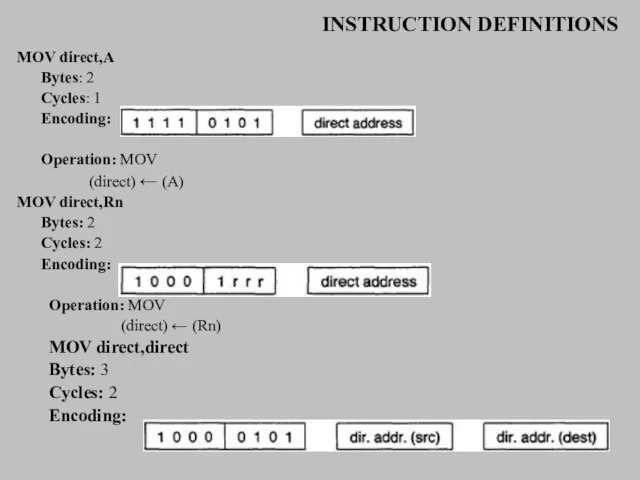
- 41. INSTRUCTION DEFINITIONS MOV direct,A Bytes: 2 Cycles: 1 Encoding: Operation: MOV (direct) ← (A) MOV direct,Rn
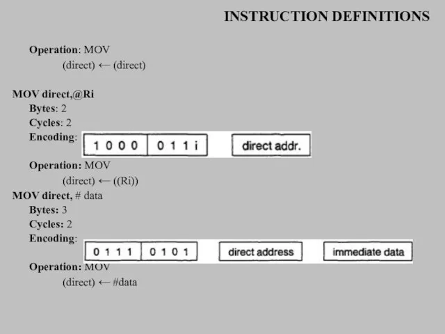
- 42. INSTRUCTION DEFINITIONS Operation: MOV (direct) ← (direct) MOV direct,@Ri Bytes: 2 Cycles: 2 Encoding: Operation: MOV
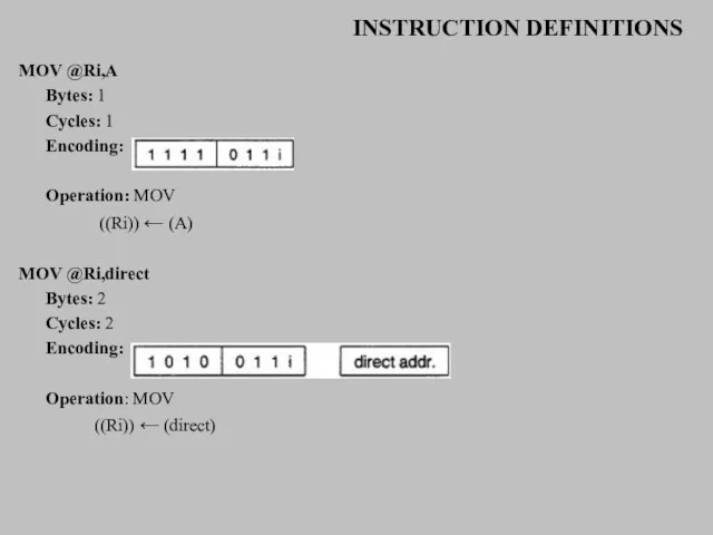
- 43. INSTRUCTION DEFINITIONS MOV @Ri,A Bytes: 1 Cycles: 1 Encoding: Operation: MOV ((Ri)) ← (A) MOV @Ri,direct
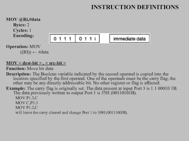
- 44. INSTRUCTION DEFINITIONS MOV @Ri,#data Bytes: 2 Cycles: 1 Encoding: Operation: MOV ((RI)) ← #data MOV ,
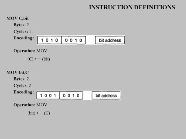
- 45. INSTRUCTION DEFINITIONS MOV C,bit Bytes: 2 Cycles: 1 Encoding: Operation: MOV (C) ← (bit) MOV bit,C
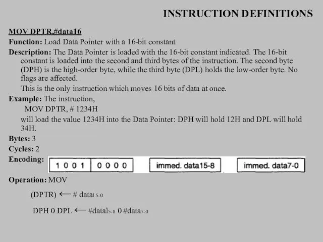
- 46. INSTRUCTION DEFINITIONS MOV DPTR,#data16 Function: Load Data Pointer with a 16-bit constant Description: The Data Pointer
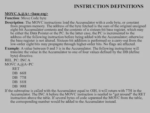
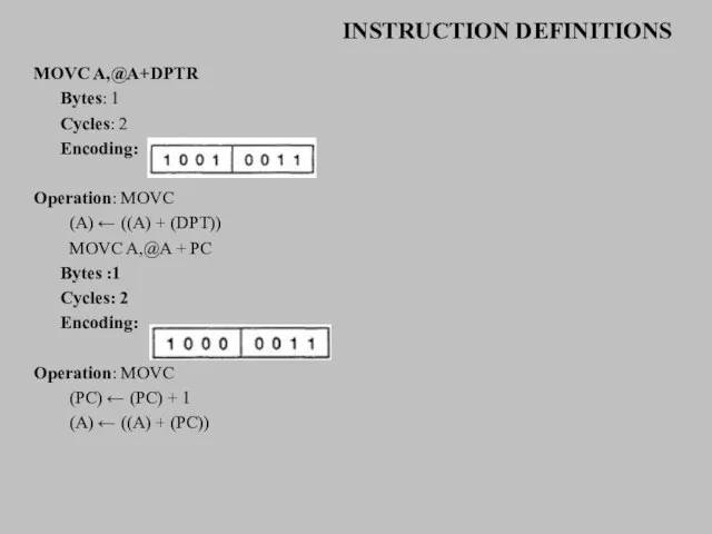
- 48. INSTRUCTION DEFINITIONS MOVC A,@A+ Function: Move Code byte Description: The MOVC instructions load the Accumulator with
- 49. INSTRUCTION DEFINITIONS MOVC A,@A+DPTR Bytes: 1 Cycles: 2 Encoding: Operation: MOVC (A) ← ((A) + (DPT))
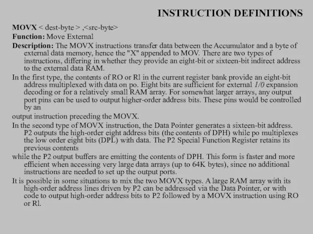
- 50. INSTRUCTION DEFINITIONS MOVX , Function: Move External Description: The MOVX instructions transfer data between the Accumulator
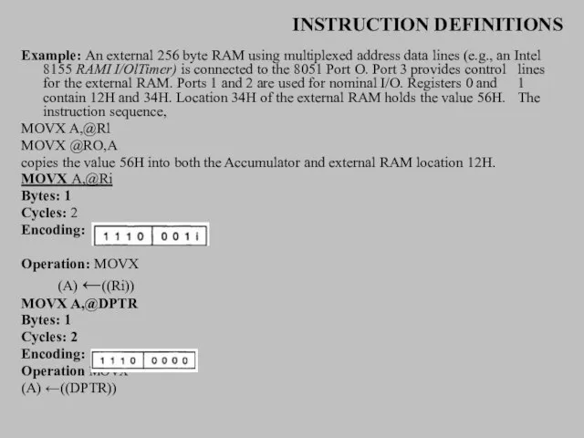
- 51. INSTRUCTION DEFINITIONS Example: An external 256 byte RAM using multiplexed address data lines (e.g., an Intel
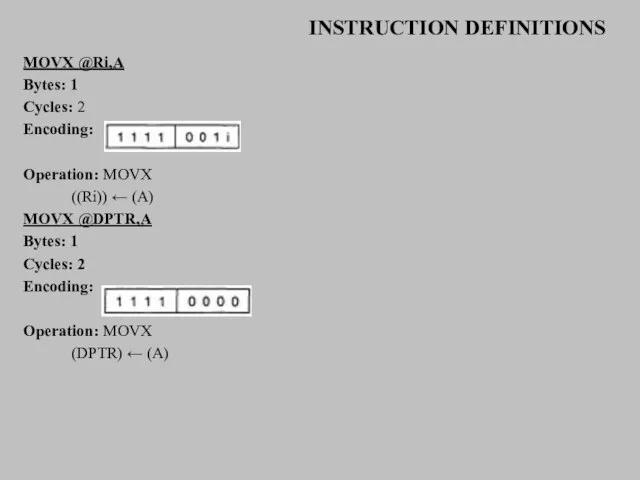
- 52. INSTRUCTION DEFINITIONS MOVX @Ri,A Bytes: 1 Cycles: 2 Encoding: Operation: MOVX ((Ri)) ← (A) MOVX @DPTR,A
- 53. INSTRUCTION DEFINITIONS MUL AB Function: Multiply Description: MUL AB multiplies the unsigned eight-bit integers in the
- 54. INSTRUCTION DEFINITIONS NOP Function: No Operation Description: Execution continues at the following instruction. Other than the
- 55. INSTRUCTION DEFINITIONS ORL Function: Logical-OR for byte variables Description: ORL performs the bitwise logical-OR operation between
- 56. INSTRUCTION DEFINITIONS ORL A,Rn Bytes: 1 Cycles: 1 Encoding: Operation: ORL (A)← (A) V (Rn) ORL
- 57. INSTRUCTION DEFINITIONS ORL C,bit Bytes: 2 Cycles: 2 Encoding: Operation: ORL (C) ← (C) V (bit)
- 58. INSTRUCTION DEFINITIONS Bytes: 2 Cycles: 2 Encoding: Operation: POP (direct) ← ((SP)) (SP) ← (SP )
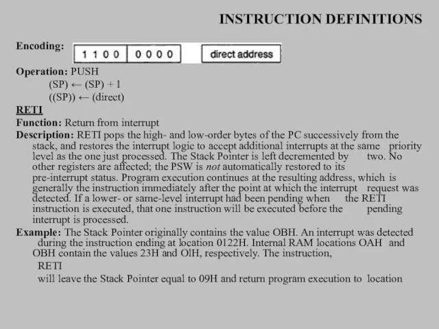
- 59. INSTRUCTION DEFINITIONS Encoding: Operation: PUSH (SP) ← (SP) + 1 ((SP)) ← (direct) RETI Function: Return
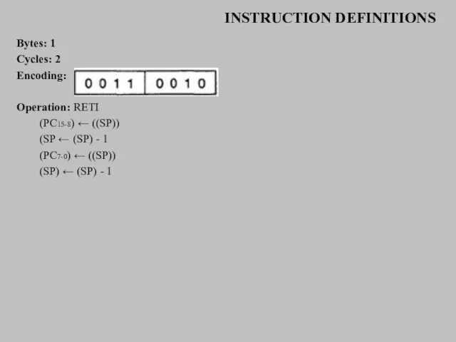
- 60. INSTRUCTION DEFINITIONS Bytes: 1 Cycles: 2 Encoding: Operation: RETI (PC15-8) ← ((SP)) (SP ← (SP) -
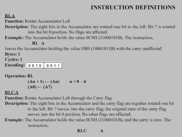
- 61. INSTRUCTION DEFINITIONS RL A Function: Rotate Accumulator Left Description: The eight bits in the Accumulator are
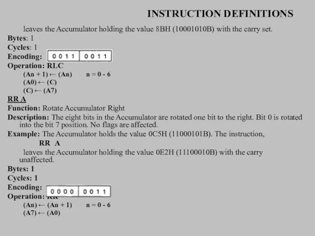
- 62. INSTRUCTION DEFINITIONS leaves the Accumulator holding the value 8BH (10001010B) with the carry set. Bytes: 1
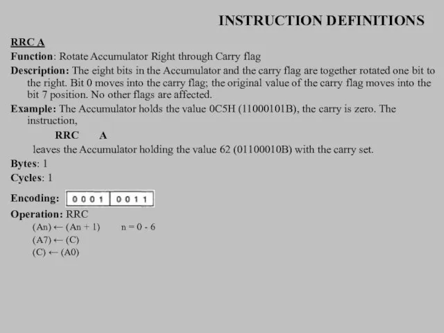
- 63. INSTRUCTION DEFINITIONS RRC A Function: Rotate Accumulator Right through Carry flag Description: The eight bits in
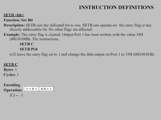
- 64. INSTRUCTION DEFINITIONS SETB Function: Set Bit Description: SETB sets the indicated bit to one. SETB can
- 65. INSTRUCTION DEFINITIONS SETB bit Bytes: 2 Cycles: 1 Encoding: Operation: SETB (bit) ← 1 SJMP rel
- 66. INSTRUCTION DEFINITIONS Bytes: 2 Cycles: 2 Encoding: Operation: SJMP (PC) ← (PC) + 2 (PC) ←
- 67. INSTRUCTION DEFINITIONS Example: The Accumulator holds 0C9H (11001001B), register 2 holds 54H (01010100B), and the carry
- 68. INSTRUCTION DEFINITIONS SUBB A,direct Bytes: 2 Cycles: 1 Encoding: Operation: SUBB (A) ← (A) - (C)
- 69. INSTRUCTION DEFINITIONS SUBB A,#data Bytes: 2 Cycles: 1 Encoding: Operation: SUBB (A) ← (A) - (C)
- 71. INSTRUCTION DEFINITIONS XCH A, Function: Exchange Accumulator with byte variable Description: XCH loads the Accumulator with
- 72. INSTRUCTION DEFINITIONS Operation: XCH XCH A,direct Bytes: 2 Cycles: 1 Encoding: Operation: XCH XCH A,@Ri Bytes:
- 73. INSTRUCTION DEFINITIONS XCHD A,@Ri Function: Exchange Digit Description: XCHD exchanges the low-order nibble of the Accumulator
- 74. INSTRUCTION DEFINITIONS XRL , Function: Logical Exclusive-OR for byte variables Description: XRL performs the bitwise logical
- 75. INSTRUCTION DEFINITIONS XRL A,Rn Bytes: 1 Cycles: 1 Encoding: Operation: XRL XRL A,direct Bytes: 2 Cycles:
- 76. INSTRUCTION DEFINITIONS XRL A,@Ri Bytes: 1 Cycles: 1 Encoding: Operation: XRL XRL A,#data Bytes: 2 Cycles:
- 78. Скачать презентацию
Слайд 2INSTRUCTION DEFINITIONS
ACALL addr11
Function: Absolute Call
Description: ACALL unconditionally calls a subroutine located at
INSTRUCTION DEFINITIONS
ACALL addr11
Function: Absolute Call
Description: ACALL unconditionally calls a subroutine located at
Слайд 3INSTRUCTION DEFINITIONS
ACALL SUBRTN
at location 0123H, SP will contain 09H, internal RAM locations
INSTRUCTION DEFINITIONS
ACALL SUBRTN
at location 0123H, SP will contain 09H, internal RAM locations
Слайд 4INSTRUCTION DEFINITIONS
ADD A,
Function: Add
Description: ADD adds the byte variable indicated
INSTRUCTION DEFINITIONS
ADD A,
Function: Add
Description: ADD adds the byte variable indicated
Слайд 5INSTRUCTION DEFINITIONS
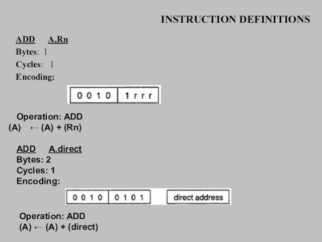
ADD A,Rn
Bytes: 1
Cycles: 1
Encoding:
Operation: ADD
← (A) + (Rn)
ADD A,direct
Bytes: 2
Cycles: 1
Encoding:
Operation:
INSTRUCTION DEFINITIONS
ADD A,Rn
Bytes: 1
Cycles: 1
Encoding:
Operation: ADD
← (A) + (Rn)
ADD A,direct
Bytes: 2
Cycles: 1
Encoding:
Operation:
Слайд 6INSTRUCTION DEFINITIONS
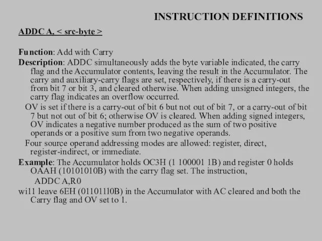
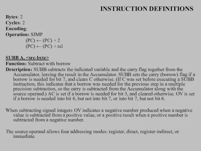
ADDC A, < src-byte >
Function: Add with Carry
Description: ADDC simultaneously adds
INSTRUCTION DEFINITIONS
ADDC A, < src-byte >
Function: Add with Carry
Description: ADDC simultaneously adds
Слайд 7INSTRUCTION DEFINITIONS
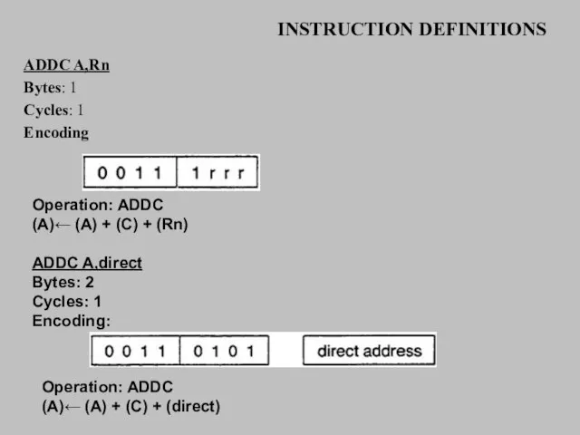
ADDC A,Rn
Bytes: 1
Cycles: 1
Encoding
Operation: ADDC
(A)← (A) + (C) + (Rn)
ADDC
INSTRUCTION DEFINITIONS
ADDC A,Rn
Bytes: 1
Cycles: 1
Encoding
Operation: ADDC
(A)← (A) + (C) + (Rn)
ADDC
Слайд 8INSTRUCTION DEFINITIONS
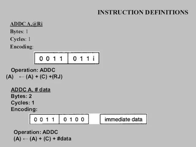
ADDC A,@Ri
Bytes: 1
Cycles: 1
Encoding:
Operation: ADDC
← (A) + (C) +(RJ)
ADDC A,
INSTRUCTION DEFINITIONS
ADDC A,@Ri
Bytes: 1
Cycles: 1
Encoding:
Operation: ADDC
← (A) + (C) +(RJ)
ADDC A,
Слайд 9INSTRUCTION DEFINITIONS
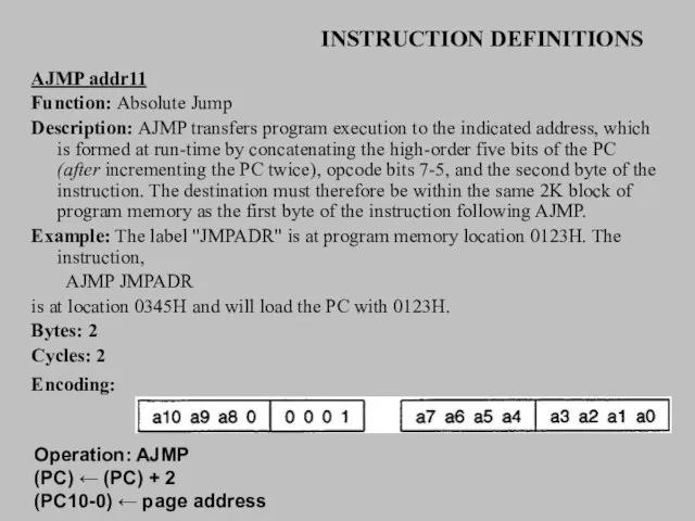
AJMP addr11
Function: Absolute Jump
Description: AJMP transfers program execution to the indicated
INSTRUCTION DEFINITIONS
AJMP addr11
Function: Absolute Jump
Description: AJMP transfers program execution to the indicated
Слайд 10INSTRUCTION DEFINITIONS
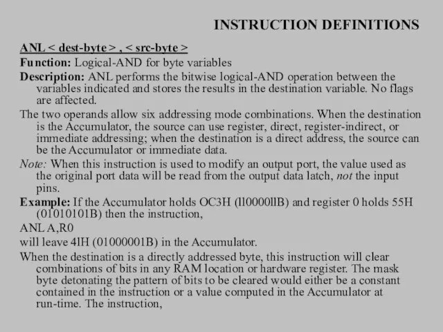
ANL < dest-byte > , < src-byte >
Function: Logical-AND for byte
INSTRUCTION DEFINITIONS
ANL < dest-byte > , < src-byte >
Function: Logical-AND for byte
Слайд 11INSTRUCTION DEFINITIONS
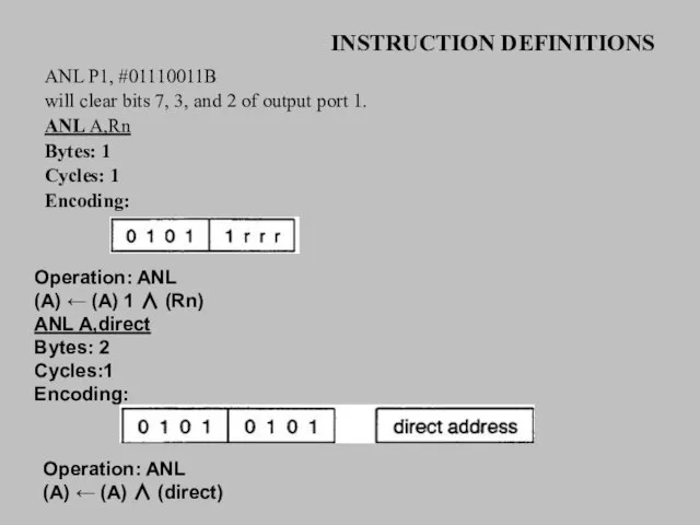
ANL P1, #01110011B
will clear bits 7, 3, and 2 of output
INSTRUCTION DEFINITIONS
ANL P1, #01110011B
will clear bits 7, 3, and 2 of output
Слайд 12INSTRUCTION DEFINITIONS
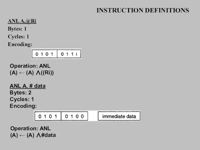
ANL A,@Ri
Bytes: 1
Cycles: 1
Encoding:
Operation: ANL
(A) ← (A) ∧((Ri))
ANL A, #
INSTRUCTION DEFINITIONS
ANL A,@Ri
Bytes: 1
Cycles: 1
Encoding:
Operation: ANL
(A) ← (A) ∧((Ri))
ANL A, #
Слайд 13INSTRUCTION DEFINITIONS
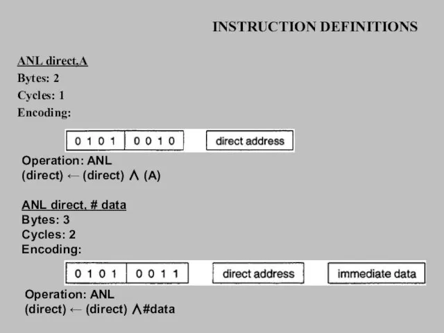
ANL direct,A
Bytes: 2
Cycles: 1
Encoding:
Operation: ANL
(direct) ← (direct) ∧ (A)
ANL direct,
INSTRUCTION DEFINITIONS
ANL direct,A
Bytes: 2
Cycles: 1
Encoding:
Operation: ANL
(direct) ← (direct) ∧ (A)
ANL direct,
Слайд 14INSTRUCTION DEFINITIONS
ANL C,
Function: Logical-AND for bit variables
Description: If the Boolean value
INSTRUCTION DEFINITIONS
ANL C,
Function: Logical-AND for bit variables
Description: If the Boolean value
Слайд 15INSTRUCTION DEFINITIONS
CJNE < dest-byte > , < src-byte >, rei
Function: Compare and
INSTRUCTION DEFINITIONS
CJNE < dest-byte > , < src-byte >, rei
Function: Compare and
Слайд 16INSTRUCTION DEFINITIONS
sets the carry flag and branches to the instruction at label
INSTRUCTION DEFINITIONS
sets the carry flag and branches to the instruction at label
Слайд 17INSTRUCTION DEFINITIONS
Operation: (PC) ← (PC) + 3
IF (A) < > (direct)
THEN
(PC) +-
INSTRUCTION DEFINITIONS
Operation: (PC) ← (PC) + 3
IF (A) < > (direct)
THEN
(PC) +-
Слайд 18INSTRUCTION DEFINITIONS
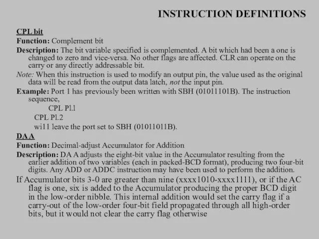
CPL bit
Function: Complement bit
Description: The bit variable specified is complemented. A
INSTRUCTION DEFINITIONS
CPL bit
Function: Complement bit
Description: The bit variable specified is complemented. A
Слайд 19INSTRUCTION DEFINITIONS
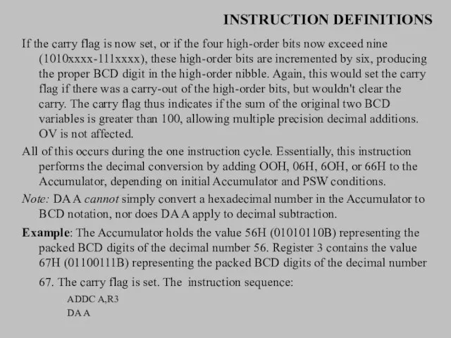
If the carry flag is now set, or if the four
INSTRUCTION DEFINITIONS
If the carry flag is now set, or if the four
Слайд 20INSTRUCTION DEFINITIONS
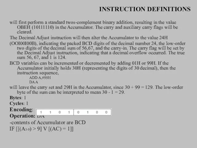
will first perform a standard twos-complement binary addition, resulting in the
INSTRUCTION DEFINITIONS
will first perform a standard twos-complement binary addition, resulting in the
Слайд 21INSTRUCTION DEFINITIONS
THEN(A3-0) ← (A3-0) + 6
AND
IF [[(A7-4) > 9] V [(C) =
INSTRUCTION DEFINITIONS
THEN(A3-0) ← (A3-0) + 6
AND
IF [[(A7-4) > 9] V [(C) =
![INSTRUCTION DEFINITIONS THEN(A3-0) ← (A3-0) + 6 AND IF [[(A7-4) > 9]](/_ipx/f_webp&q_80&fit_contain&s_1440x1080/imagesDir/jpg/376131/slide-20.jpg)
Слайд 22INSTRUCTION DEFINITIONS
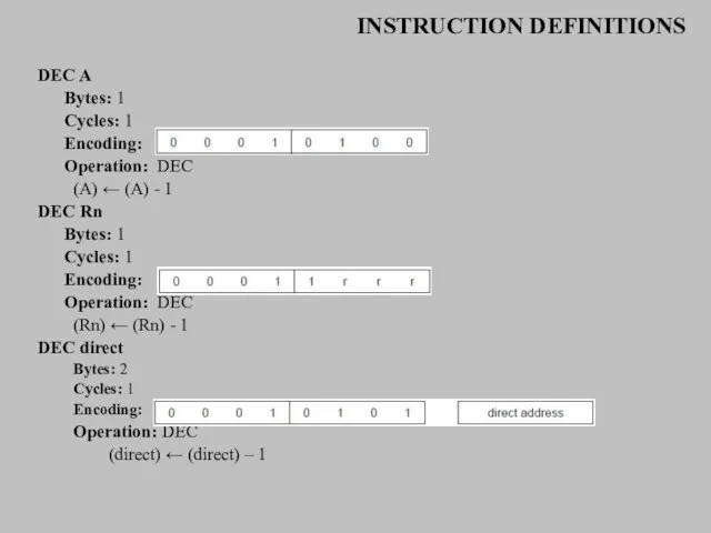
DEC A
Bytes: 1
Cycles: 1
Encoding:
Operation: DEC
(A) ← (A) - 1
DEC Rn
Bytes: 1
Cycles:
INSTRUCTION DEFINITIONS
DEC A
Bytes: 1
Cycles: 1
Encoding:
Operation: DEC
(A) ← (A) - 1
DEC Rn
Bytes: 1
Cycles:
Слайд 23INSTRUCTION DEFINITIONS
DIV AB
Function: Divide
Description: DIV AB divides the unsigned eight-bit integer in
INSTRUCTION DEFINITIONS
DIV AB
Function: Divide
Description: DIV AB divides the unsigned eight-bit integer in
Слайд 24INSTRUCTION DEFINITIONS
DJNZ ,
Function: Decrement and Jump if Not Zero
Description: DJNZ decrements the
INSTRUCTION DEFINITIONS
DJNZ
Function: Decrement and Jump if Not Zero
Description: DJNZ decrements the
Слайд 25INSTRUCTION DEFINITIONS
toggles P1.7 eight times, causing four output pulses to appear at
INSTRUCTION DEFINITIONS
toggles P1.7 eight times, causing four output pulses to appear at
Слайд 26INSTRUCTION DEFINITIONS
INC
Function: Increment
Description: INC increments the indicated variable by 1. An
INSTRUCTION DEFINITIONS
INC
Function: Increment
Description: INC increments the indicated variable by 1. An
Слайд 27INSTRUCTION DEFINITIONS
INC Rn
Bytes: 1
Cycles: 1
Encoding:
Operation: INC
(Rn) ← (Rn) + 1
INC
INSTRUCTION DEFINITIONS
INC Rn
Bytes: 1
Cycles: 1
Encoding:
Operation: INC
(Rn) ← (Rn) + 1
INC
Слайд 28INSTRUCTION DEFINITIONS
INC DPTR
Function: Increment Data Pointer
Description: INC DPTR increments the 16-bit data
INSTRUCTION DEFINITIONS
INC DPTR
Function: Increment Data Pointer
Description: INC DPTR increments the 16-bit data

Слайд 29INSTRUCTION DEFINITIONS
JB blt,rel
Function: Jump if Bit set
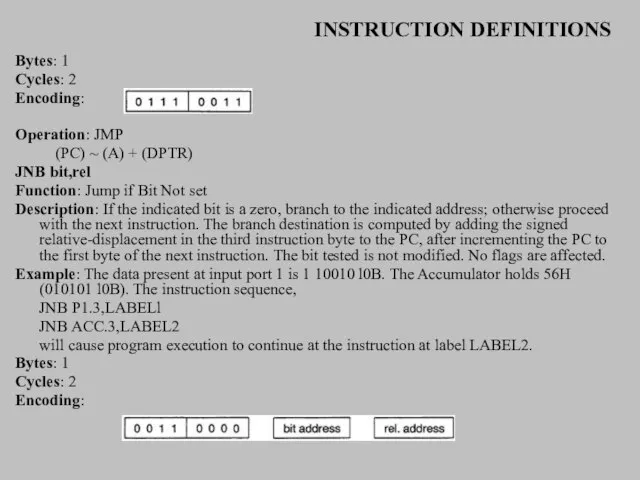
Description: If the indicated bit is
INSTRUCTION DEFINITIONS
JB blt,rel
Function: Jump if Bit set
Description: If the indicated bit is
Слайд 30INSTRUCTION DEFINITIONS
JBC bit,rel
Function: Jump if Bit is set and Clear bit
Description: If
INSTRUCTION DEFINITIONS
JBC bit,rel
Function: Jump if Bit is set and Clear bit
Description: If
Слайд 31INSTRUCTION DEFINITIONS
JC rel
Function: Jump if Carry is set
Description: If the carry flag
INSTRUCTION DEFINITIONS
JC rel
Function: Jump if Carry is set
Description: If the carry flag
Слайд 32INSTRUCTION DEFINITIONS
JMP @A+DPTR
Function: Jump indirect
Description: Add the eight-bit unsigned contents of the
INSTRUCTION DEFINITIONS
JMP @A+DPTR
Function: Jump indirect
Description: Add the eight-bit unsigned contents of the
Слайд 33INSTRUCTION DEFINITIONS
Bytes: 1
Cycles: 2
Encoding:
Operation: JMP
(PC) ~ (A) + (DPTR)
JNB bit,rel
Function:
INSTRUCTION DEFINITIONS
Bytes: 1
Cycles: 2
Encoding:
Operation: JMP
(PC) ~ (A) + (DPTR)
JNB bit,rel
Function:
Слайд 34INSTRUCTION DEFINITIONS
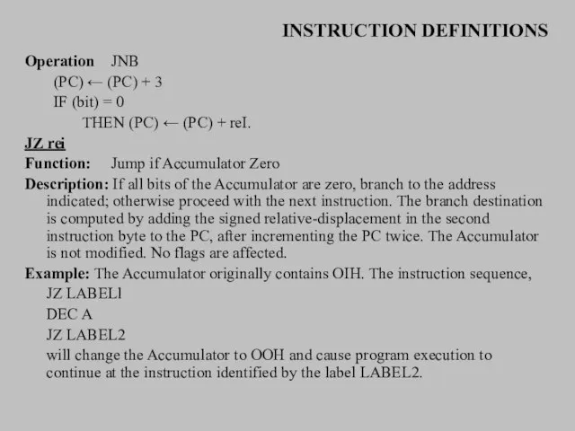
Operation JNB
(PC) ← (PC) + 3
IF (bit) = 0
THEN (PC) ← (PC)
INSTRUCTION DEFINITIONS
Operation JNB
(PC) ← (PC) + 3
IF (bit) = 0
THEN (PC) ← (PC)
Слайд 35INSTRUCTION DEFINITIONS
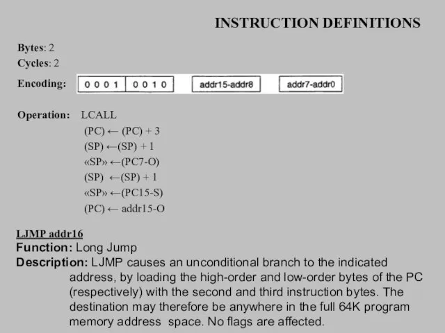
Bytes: 2
Cycles: 2
Encoding:
Operation: LCALL
(PC) ← (PC) + 3
(SP) ←(SP) +
INSTRUCTION DEFINITIONS
Bytes: 2
Cycles: 2
Encoding:
Operation: LCALL
(PC) ← (PC) + 3
(SP) ←(SP) +
Слайд 36INSTRUCTION DEFINITIONS
Example: The label "JMPADR" is assigned to the instruction at program
INSTRUCTION DEFINITIONS
Example: The label "JMPADR" is assigned to the instruction at program
Слайд 37INSTRUCTION DEFINITIONS
MOV RO,#30H ;RO <= 30H
MOV A,@RO ;A <= 40H
MOV Rl,A
INSTRUCTION DEFINITIONS
MOV RO,#30H ;RO <= 30H
MOV A,@RO ;A <= 40H
MOV Rl,A
Слайд 38INSTRUCTION DEFINITIONS
MOV A,direct
Bytes: 2
Cycles:
Encoding:
Operation: MOV
(A) ←(direct)
MOV A,ACC is not a valid instruction.
MOV
INSTRUCTION DEFINITIONS
MOV A,direct
Bytes: 2
Cycles:
Encoding:
Operation: MOV
(A) ←(direct)
MOV A,ACC is not a valid instruction.
MOV
Слайд 39INSTRUCTION DEFINITIONS
MOV A, # data
Bytes: 2
Cycles: 1
Encoding:
Operation: MOV
(A) ← #data
MOV Rn,A
Bytes:
INSTRUCTION DEFINITIONS
MOV A, # data
Bytes: 2
Cycles: 1
Encoding:
Operation: MOV
(A) ← #data
MOV Rn,A
Bytes:
Слайд 40INSTRUCTION DEFINITIONS
MOV Rn,direct
Bytes: 2
Cycles: 2
Encoding:
Operation: MOV
(Rn) ← (direct)
MOV Rn, #
INSTRUCTION DEFINITIONS
MOV Rn,direct
Bytes: 2
Cycles: 2
Encoding:
Operation: MOV
(Rn) ← (direct)
MOV Rn, #
Слайд 41INSTRUCTION DEFINITIONS
MOV direct,A
Bytes: 2
Cycles: 1
Encoding:
Operation: MOV
(direct) ← (A)
MOV direct,Rn
Bytes: 2
Cycles:
INSTRUCTION DEFINITIONS
MOV direct,A
Bytes: 2
Cycles: 1
Encoding:
Operation: MOV
(direct) ← (A)
MOV direct,Rn
Bytes: 2
Cycles:
Слайд 42INSTRUCTION DEFINITIONS
Operation: MOV
(direct) ← (direct)
MOV direct,@Ri
Bytes: 2
Cycles: 2
Encoding:
Operation: MOV
(direct) ←
INSTRUCTION DEFINITIONS
Operation: MOV
(direct) ← (direct)
MOV direct,@Ri
Bytes: 2
Cycles: 2
Encoding:
Operation: MOV
(direct) ←
Слайд 43INSTRUCTION DEFINITIONS
MOV @Ri,A
Bytes: 1
Cycles: 1
Encoding:
Operation: MOV
((Ri)) ← (A)
MOV @Ri,direct
Bytes:
INSTRUCTION DEFINITIONS
MOV @Ri,A
Bytes: 1
Cycles: 1
Encoding:
Operation: MOV
((Ri)) ← (A)
MOV @Ri,direct
Bytes:
Слайд 44INSTRUCTION DEFINITIONS
MOV @Ri,#data
Bytes: 2
Cycles: 1
Encoding:
Operation: MOV
((RI)) ← #data
MOV <
INSTRUCTION DEFINITIONS
MOV @Ri,#data
Bytes: 2
Cycles: 1
Encoding:
Operation: MOV
((RI)) ← #data
MOV <
Слайд 45INSTRUCTION DEFINITIONS
MOV C,bit
Bytes: 2
Cycles: 1
Encoding:
Operation: MOV
(C) ← (bit)
MOV bit,C
Bytes: 2
Cycles:
INSTRUCTION DEFINITIONS
MOV C,bit
Bytes: 2
Cycles: 1
Encoding:
Operation: MOV
(C) ← (bit)
MOV bit,C
Bytes: 2
Cycles:
Слайд 46INSTRUCTION DEFINITIONS
MOV DPTR,#data16
Function: Load Data Pointer with a 16-bit constant
Description: The Data
INSTRUCTION DEFINITIONS
MOV DPTR,#data16
Function: Load Data Pointer with a 16-bit constant
Description: The Data

Слайд 48INSTRUCTION DEFINITIONS
MOVC A,@A+
Function: Move Code byte
Description: The MOVC instructions load the
INSTRUCTION DEFINITIONS
MOVC A,@A+
Function: Move Code byte
Description: The MOVC instructions load the
Слайд 49INSTRUCTION DEFINITIONS
MOVC A,@A+DPTR
Bytes: 1
Cycles: 2
Encoding:
Operation: MOVC
(A) ← ((A) + (DPT))
MOVC A,@A
INSTRUCTION DEFINITIONS
MOVC A,@A+DPTR
Bytes: 1
Cycles: 2
Encoding:
Operation: MOVC
(A) ← ((A) + (DPT))
MOVC A,@A
Слайд 50INSTRUCTION DEFINITIONS
MOVX < dest-byte > ,
Function: Move External
Description: The MOVX instructions transfer
INSTRUCTION DEFINITIONS
MOVX < dest-byte > ,
Function: Move External
Description: The MOVX instructions transfer
Слайд 51INSTRUCTION DEFINITIONS
Example: An external 256 byte RAM using multiplexed address data lines
INSTRUCTION DEFINITIONS
Example: An external 256 byte RAM using multiplexed address data lines
Слайд 52INSTRUCTION DEFINITIONS
MOVX @Ri,A
Bytes: 1
Cycles: 2
Encoding:
Operation: MOVX
((Ri)) ← (A)
MOVX @DPTR,A
Bytes: 1
Cycles: 2
Encoding:
INSTRUCTION DEFINITIONS
MOVX @Ri,A
Bytes: 1
Cycles: 2
Encoding:
Operation: MOVX
((Ri)) ← (A)
MOVX @DPTR,A
Bytes: 1
Cycles: 2
Encoding:
Слайд 53INSTRUCTION DEFINITIONS
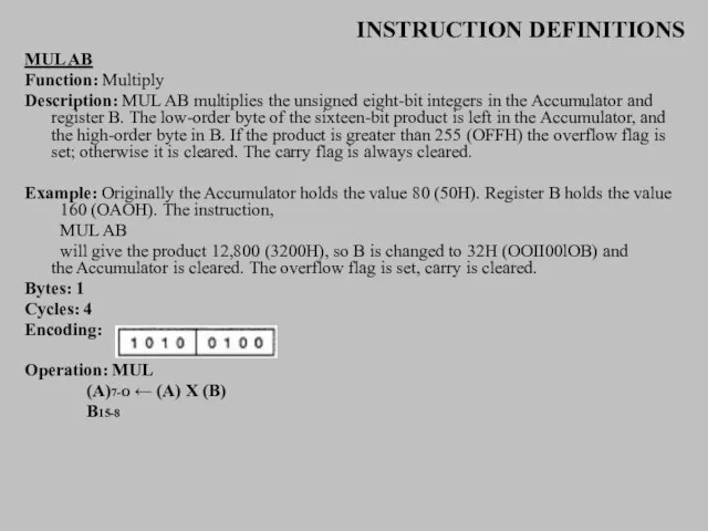
MUL AB
Function: Multiply
Description: MUL AB multiplies the unsigned eight-bit integers in
INSTRUCTION DEFINITIONS
MUL AB
Function: Multiply
Description: MUL AB multiplies the unsigned eight-bit integers in
Слайд 54INSTRUCTION DEFINITIONS
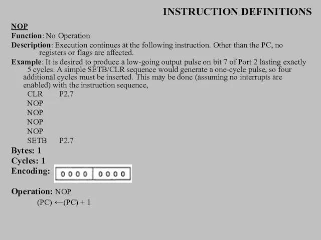
NOP
Function: No Operation
Description: Execution continues at the following instruction. Other than
INSTRUCTION DEFINITIONS
NOP
Function: No Operation
Description: Execution continues at the following instruction. Other than
Слайд 55INSTRUCTION DEFINITIONS
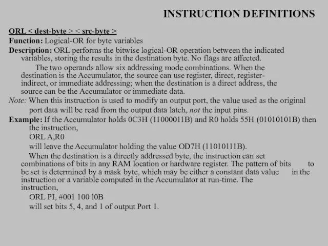
ORL < dest-byte > < src-byte >
Function: Logical-OR for byte variables
Description:
INSTRUCTION DEFINITIONS
ORL < dest-byte > < src-byte >
Function: Logical-OR for byte variables
Description:
Слайд 56INSTRUCTION DEFINITIONS
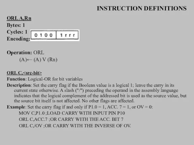
ORL A,Rn
Bytes: 1
Cycles: 1
Encoding:
Operation: ORL
(A)← (A) V (Rn)
ORL C,
Function:
INSTRUCTION DEFINITIONS
ORL A,Rn
Bytes: 1
Cycles: 1
Encoding:
Operation: ORL
(A)← (A) V (Rn)
ORL C,
Function:
Слайд 57INSTRUCTION DEFINITIONS
ORL C,bit
Bytes: 2
Cycles: 2
Encoding:
Operation: ORL
(C) ← (C) V (bit)
POP
INSTRUCTION DEFINITIONS
ORL C,bit
Bytes: 2
Cycles: 2
Encoding:
Operation: ORL
(C) ← (C) V (bit)
POP
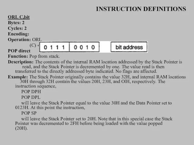
Слайд 58INSTRUCTION DEFINITIONS
Bytes: 2
Cycles: 2
Encoding:
Operation: POP
(direct) ← ((SP))
(SP) ← (SP
INSTRUCTION DEFINITIONS
Bytes: 2
Cycles: 2
Encoding:
Operation: POP
(direct) ← ((SP))
(SP) ← (SP
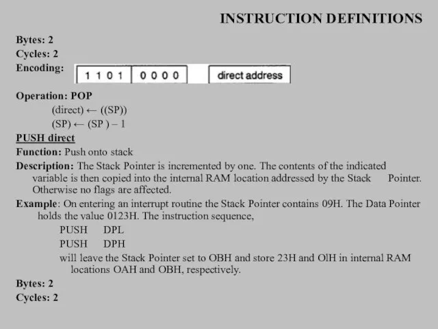
Слайд 59INSTRUCTION DEFINITIONS
Encoding:
Operation: PUSH
(SP) ← (SP) + 1
((SP)) ← (direct)
RETI
Function:
INSTRUCTION DEFINITIONS
Encoding:
Operation: PUSH
(SP) ← (SP) + 1
((SP)) ← (direct)
RETI
Function:
Слайд 60INSTRUCTION DEFINITIONS
Bytes: 1
Cycles: 2
Encoding:
Operation: RETI
(PC15-8) ← ((SP))
(SP ← (SP) - 1
(PC7-0)
INSTRUCTION DEFINITIONS
Bytes: 1
Cycles: 2
Encoding:
Operation: RETI
(PC15-8) ← ((SP))
(SP ← (SP) - 1
(PC7-0)
Слайд 61INSTRUCTION DEFINITIONS
RL A
Function: Rotate Accumulator Left
Description: The eight bits in the Accumulator
INSTRUCTION DEFINITIONS
RL A
Function: Rotate Accumulator Left
Description: The eight bits in the Accumulator
Слайд 62INSTRUCTION DEFINITIONS
leaves the Accumulator holding the value 8BH (10001010B) with the carry
INSTRUCTION DEFINITIONS
leaves the Accumulator holding the value 8BH (10001010B) with the carry
Слайд 63INSTRUCTION DEFINITIONS
RRC A
Function: Rotate Accumulator Right through Carry flag
Description: The eight bits
INSTRUCTION DEFINITIONS
RRC A
Function: Rotate Accumulator Right through Carry flag
Description: The eight bits
Слайд 64INSTRUCTION DEFINITIONS
SETB
Function: Set Bit
Description: SETB sets the indicated bit to one.
INSTRUCTION DEFINITIONS
SETB
Function: Set Bit
Description: SETB sets the indicated bit to one.
Слайд 65INSTRUCTION DEFINITIONS
SETB bit
Bytes: 2
Cycles: 1
Encoding:
Operation: SETB
(bit) ← 1
SJMP rel
Function: Short Jump
Description:
INSTRUCTION DEFINITIONS
SETB bit
Bytes: 2
Cycles: 1
Encoding:
Operation: SETB
(bit) ← 1
SJMP rel
Function: Short Jump
Description:
Слайд 66INSTRUCTION DEFINITIONS
Bytes: 2
Cycles: 2
Encoding:
Operation: SJMP
(PC) ← (PC) + 2
(PC) ← (PC)
INSTRUCTION DEFINITIONS
Bytes: 2
Cycles: 2
Encoding:
Operation: SJMP
(PC) ← (PC) + 2
(PC) ← (PC)
Слайд 67INSTRUCTION DEFINITIONS
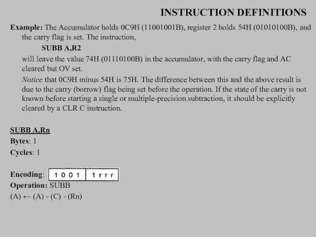
Example: The Accumulator holds 0C9H (11001001B), register 2 holds 54H (01010100B),
INSTRUCTION DEFINITIONS
Example: The Accumulator holds 0C9H (11001001B), register 2 holds 54H (01010100B),
Слайд 68INSTRUCTION DEFINITIONS
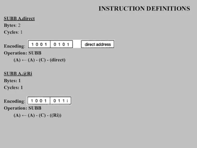
SUBB A,direct
Bytes: 2
Cycles: 1
Encoding:
Operation: SUBB
(A) ← (A) - (C) -
INSTRUCTION DEFINITIONS
SUBB A,direct
Bytes: 2
Cycles: 1
Encoding:
Operation: SUBB
(A) ← (A) - (C) -
Слайд 69INSTRUCTION DEFINITIONS
SUBB A,#data
Bytes: 2
Cycles: 1
Encoding:
Operation: SUBB
(A) ← (A) - (C) -
INSTRUCTION DEFINITIONS
SUBB A,#data
Bytes: 2
Cycles: 1
Encoding:
Operation: SUBB
(A) ← (A) - (C) -
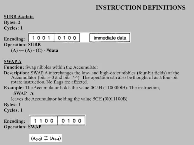

Слайд 71INSTRUCTION DEFINITIONS
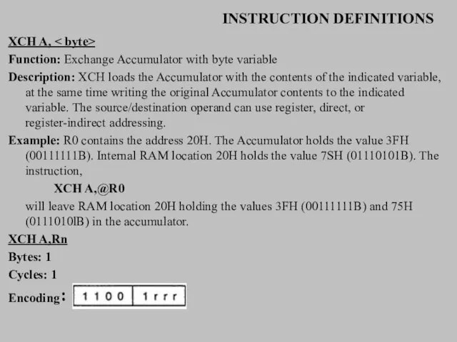
XCH A, < byte>
Function: Exchange Accumulator with byte variable
Description: XCH loads
INSTRUCTION DEFINITIONS
XCH A, < byte>
Function: Exchange Accumulator with byte variable
Description: XCH loads
Слайд 72INSTRUCTION DEFINITIONS
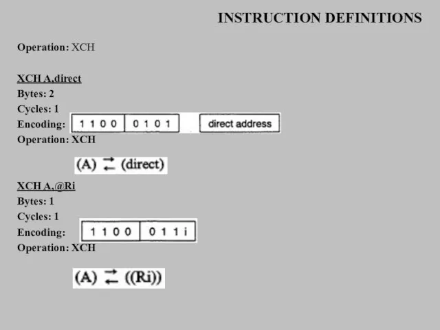
Operation: XCH
XCH A,direct
Bytes: 2
Cycles: 1
Encoding:
Operation: XCH
XCH A,@Ri
Bytes: 1
Cycles: 1
Encoding:
INSTRUCTION DEFINITIONS
Operation: XCH
XCH A,direct
Bytes: 2
Cycles: 1
Encoding:
Operation: XCH
XCH A,@Ri
Bytes: 1
Cycles: 1
Encoding:
Слайд 73INSTRUCTION DEFINITIONS
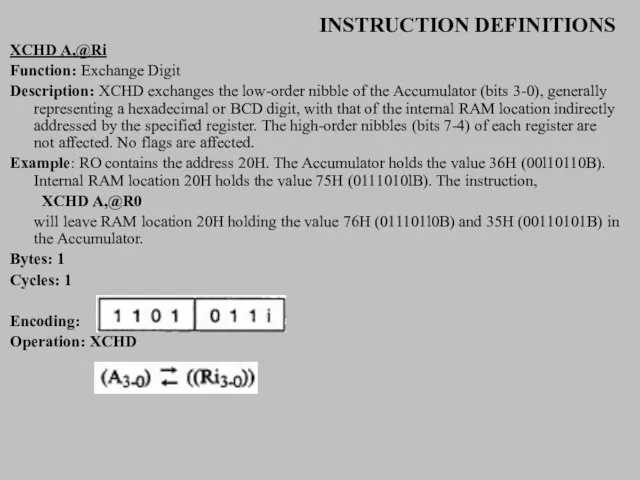
XCHD A,@Ri
Function: Exchange Digit
Description: XCHD exchanges the low-order nibble of the
INSTRUCTION DEFINITIONS
XCHD A,@Ri
Function: Exchange Digit
Description: XCHD exchanges the low-order nibble of the
Слайд 74INSTRUCTION DEFINITIONS
XRL < dest-byte > , < src-byte >
Function: Logical Exclusive-OR for
INSTRUCTION DEFINITIONS
XRL < dest-byte > , < src-byte >
Function: Logical Exclusive-OR for
Слайд 75INSTRUCTION DEFINITIONS
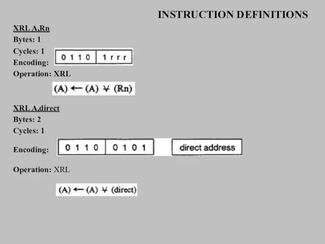
XRL A,Rn
Bytes: 1
Cycles: 1
Encoding:
Operation: XRL
XRL A,direct
Bytes: 2
Cycles: 1
Encoding:
Operation: XRL
INSTRUCTION DEFINITIONS
XRL A,Rn
Bytes: 1
Cycles: 1
Encoding:
Operation: XRL
XRL A,direct
Bytes: 2
Cycles: 1
Encoding:
Operation: XRL
Слайд 76INSTRUCTION DEFINITIONS
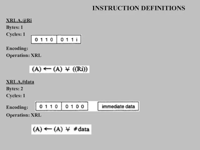
XRL A,@Ri
Bytes: 1
Cycles: 1
Encoding:
Operation: XRL
XRL A,#data
Bytes: 2
Cycles: 1
Encoding:
Operation: XRL
INSTRUCTION DEFINITIONS
XRL A,@Ri
Bytes: 1
Cycles: 1
Encoding:
Operation: XRL
XRL A,#data
Bytes: 2
Cycles: 1
Encoding:
Operation: XRL
 Функции, их свойства и графики
 Организация технической эксплуатации ТСО в части
 Коммуникативный акт
 Процессуальное оформление результатов административного расследования
 Хозяйственное использование внутренних вод Евразии
 Презентация на тему Соседи Солнца 5 класс
 FB'I. Информация о фитнес-клубе
 Государственные программы и государственные задания как инструменты повышения эффективности бюджетных расходов
 Подобие фигур вокруг нас
 Авторская школа ученого -исследователя
 Труд и творчество
 Сто лет одиночества
 Основы оценки бизнеса. Зачет по дисциплине
 Родной город (2 класс)
 «Оно оказывает значительное целебное воздействие, укрепляет желудок, останавливает рвоту, возбуждает аппетит и очищает кровь; спо
 Кинематическая схема станка СТД 120 М
 Автоцистерна
 Жиронепроницаемая бумага. Пергамент
 Маркетинговые исследования
 ЖК_ArtPlayHouse
 Правовое государство и гражданское общество
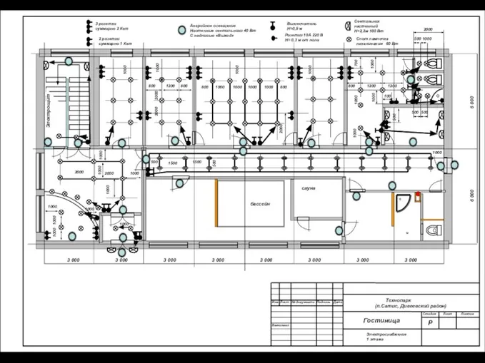 Гостиница 1 этаж
 Моя профессия - детский офтальмолог
 «Молодой герой» в литературе последних десятилетий
 АЛЛЕРГИЯ И АСТМА. ПИКФЛОУМЕТРИЯ
 «Когда исчезнет любовь, перестанет существовать человечество».
 People I am Proud of
 Вихревой эжекторный насадок-ускоритель потока выхлопных газов ДВС