- Welding-process

Содержание
- 2. Purposes of this report: - to give an outline of welding processes Welding is a process
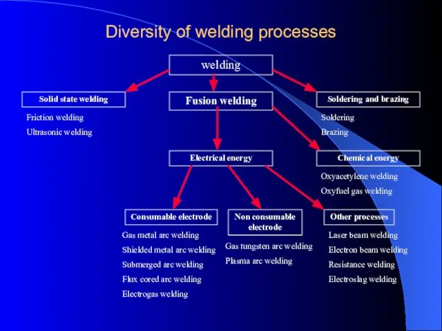
- 3. Diversity of welding processes welding Solid state welding Soldering and brazing Fusion welding Electrical energy Chemical
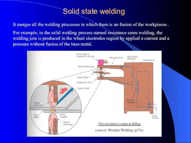
- 4. Solid state welding It merges all the welding processes in which there is no fusion of
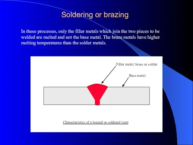
- 5. Soldering or brazing In these processes, only the filler metals which join the two pieces to
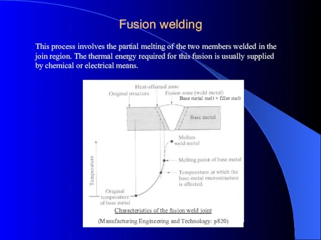
- 6. Fusion welding This process involves the partial melting of the two members welded in the join
- 7. Fusion welding Process
- 8. Topics to Discuss Introduction Oxyfuel Gas welding Arc-Welding Processes:Consumable electrode Electrodes Arc-Welding Processes:Non Consumable Process Thermit
- 9. Introduction Definition : Fusion Welding is defined as melting together and coalescing materials by means of
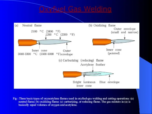
- 10. Oxyfuel Gas Welding Fig : Three basic types of oxyacetylene flames used in oxyfuel-gas welding and
- 11. Oxyfuel Gas Welding Welding process that uses fuel gas combined with oxygen to produce flame This
- 12. Types of flames Neutral flame Oxidising flame Carburising flame Filler Metals : Additional material to weld
- 13. Welding practice & equipment STEPS : Prepare the edges to be joined and maintain the proper
- 14. Torch used in Oxyacetylene Welding Fig : (a) General view of and (b) cross-section of a
- 15. Arc welding process : Consumable electrode Process goes with the consumable electrode or non consumable electrode
- 16. Shielded metal arc welding process Fig : Schematic illustration of the shielded metal-arc welding process. About
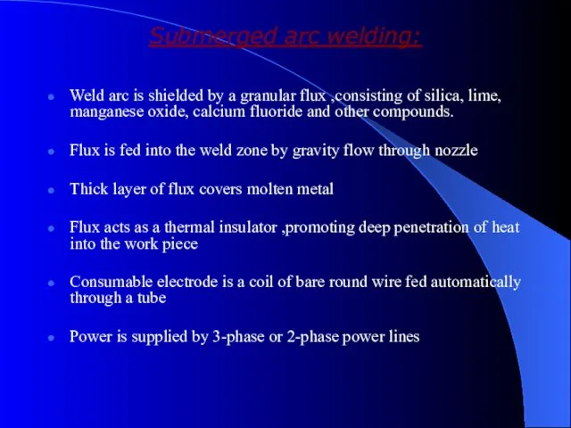
- 17. Submerged arc welding: Fig : Schematic illustration of the submerged-arc welding process and equipment. The unfused
- 18. Submerged arc welding: Weld arc is shielded by a granular flux ,consisting of silica, lime, manganese
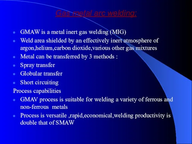
- 19. Gas metal arc welding: GMAW is a metal inert gas welding (MIG) Weld area shielded by
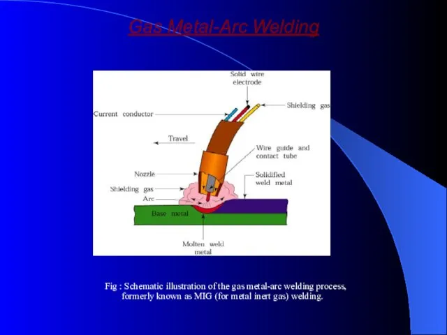
- 20. Gas Metal-Arc Welding Fig : Schematic illustration of the gas metal-arc welding process, formerly known as
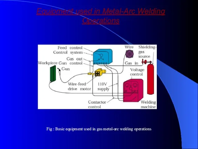
- 21. Equipment used in Metal-Arc Welding Operations Fig : Basic equipment used in gas metal-arc welding operations
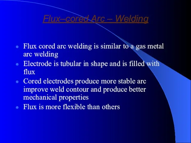
- 22. Flux–cored Arc – Welding Flux cored arc welding is similar to a gas metal arc welding
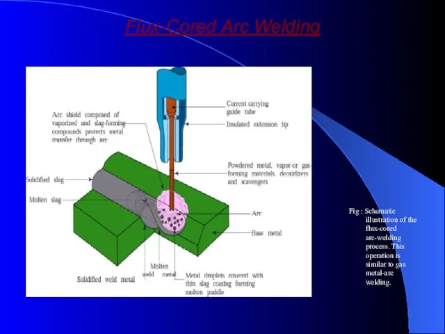
- 23. Flux-Cored Arc Welding Fig : Schematic illustration of the flux-cored arc-welding process. This operation is similar
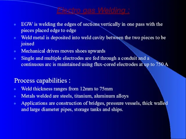
- 24. Electro gas Welding : EGW is welding the edges of sections vertically in one pass with
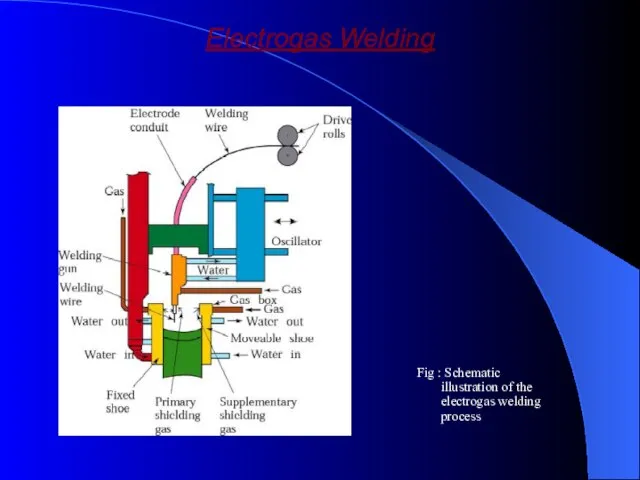
- 25. Electrogas Welding Fig : Schematic illustration of the electrogas welding process
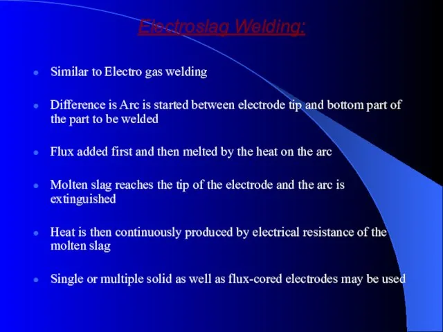
- 26. Electroslag Welding: Similar to Electro gas welding Difference is Arc is started between electrode tip and
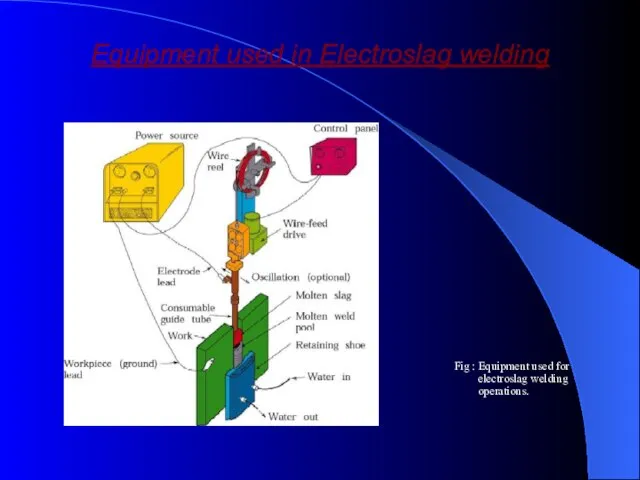
- 27. Equipment used in Electroslag welding Fig : Equipment used for electroslag welding operations.
- 28. Solid-State Welding Processes
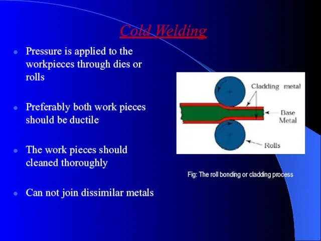
- 29. Cold Welding Pressure is applied to the workpieces through dies or rolls Preferably both work pieces
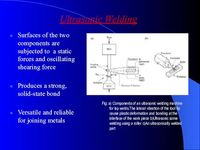
- 30. Ultrasonic Welding Surfaces of the two components are subjected to a static forces and oscillating shearing
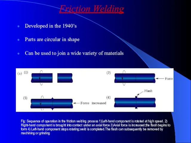
- 31. Friction Welding Developed in the 1940’s Parts are circular in shape Can be used to join
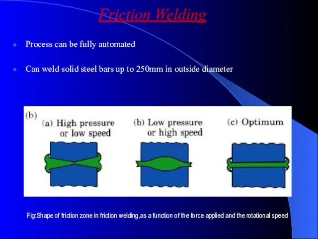
- 32. Process can be fully automated Can weld solid steel bars up to 250mm in outside diameter
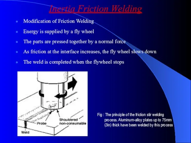
- 33. Inertia Friction Welding Modification of Friction Welding Energy is supplied by a fly wheel The parts
- 34. Linear Friction Welding Parts are joined by a linear reciprocating motion Parts do not have to
- 35. Friction Stir Welding (FSW) New Process for welding aerospace metals Research is being directed towards using
- 36. Resistance Welding Developed in the early 1900’s A process in which the heat required for welding
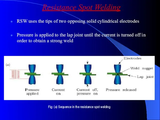
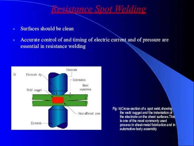
- 37. Resistance Spot Welding RSW uses the tips of two opposing solid cylindrical electrodes Pressure is applied
- 38. Surfaces should be clean Accurate control of and timing of electric current and of pressure are
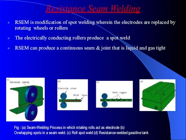
- 39. Resistance Seam Welding RSEM is modification of spot welding wherein the electrodes are replaced by rotating
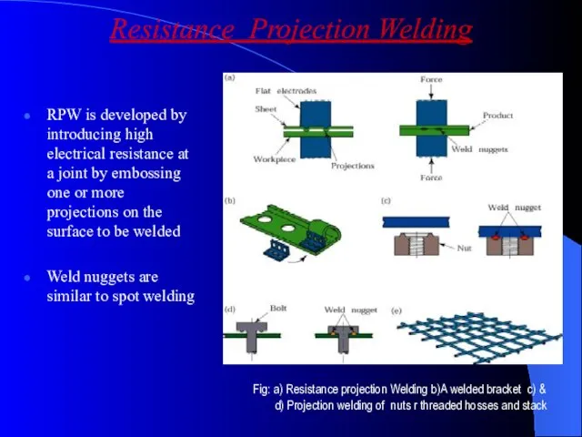
- 40. Resistance Projection Welding RPW is developed by introducing high electrical resistance at a joint by embossing
- 41. The electrodes exert pressure to compress the projections Nuts and bolts can be welded to sheet
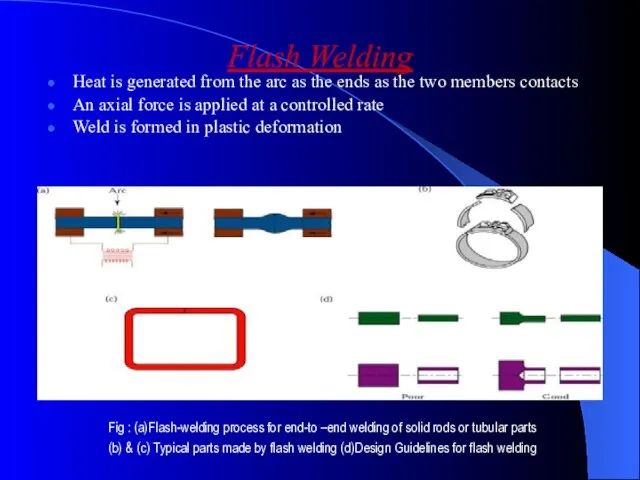
- 42. Flash Welding Heat is generated from the arc as the ends as the two members contacts
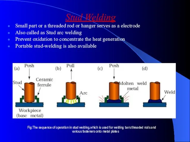
- 43. Stud Welding Small part or a threaded rod or hanger serves as a electrode Also called
- 45. Скачать презентацию
Слайд 3Diversity of welding processes
welding
Solid state welding
Soldering and brazing
Fusion welding
Electrical energy
Chemical energy
Other
Diversity of welding processes
welding
Solid state welding
Soldering and brazing
Fusion welding
Electrical energy
Chemical energy
Other
Слайд 4Solid state welding
It merges all the welding processes in which there is
Solid state welding
It merges all the welding processes in which there is
Слайд 5Soldering or brazing
In these processes, only the filler metals which join the
Soldering or brazing
In these processes, only the filler metals which join the
Слайд 6Fusion welding
This process involves the partial melting of the two members welded
Fusion welding
This process involves the partial melting of the two members welded
Слайд 7
Fusion welding Process
Fusion welding Process
Слайд 8Topics to Discuss
Introduction
Oxyfuel Gas welding
Arc-Welding Processes:Consumable electrode
Electrodes
Arc-Welding Processes:Non Consumable Process
Thermit Welding
Electron
Topics to Discuss
Introduction
Oxyfuel Gas welding
Arc-Welding Processes:Consumable electrode
Electrodes
Arc-Welding Processes:Non Consumable Process
Thermit Welding
Electron
Слайд 9Introduction
Definition : Fusion Welding is defined as melting together and coalescing
Introduction
Definition : Fusion Welding is defined as melting together and coalescing
Слайд 10Oxyfuel Gas Welding
Fig : Three basic types of oxyacetylene flames used in
Oxyfuel Gas Welding
Fig : Three basic types of oxyacetylene flames used in
Слайд 11Oxyfuel Gas Welding
Welding process that uses fuel gas combined with oxygen to
Oxyfuel Gas Welding
Welding process that uses fuel gas combined with oxygen to
Слайд 12Types of flames
Neutral flame
Oxidising flame
Carburising flame
Filler Metals :
Additional material to weld the
Types of flames
Neutral flame
Oxidising flame
Carburising flame
Filler Metals :
Additional material to weld the
Слайд 13Welding practice & equipment
STEPS :
Prepare the edges to be joined and maintain
Welding practice & equipment
STEPS :
Prepare the edges to be joined and maintain
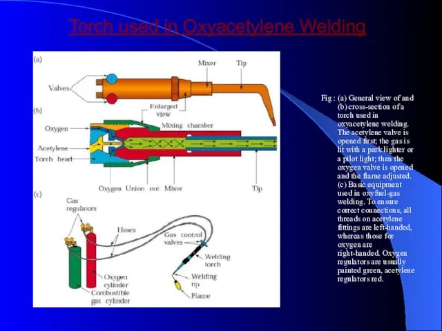
Слайд 14Torch used in Oxyacetylene Welding
Fig : (a) General view of and (b)
Torch used in Oxyacetylene Welding
Fig : (a) General view of and (b)
Слайд 15Arc welding process : Consumable electrode
Process goes with the consumable electrode or
Arc welding process : Consumable electrode
Process goes with the consumable electrode or
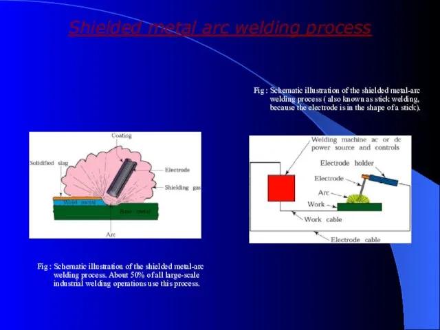
Слайд 16Shielded metal arc welding process
Fig : Schematic illustration of the shielded metal-arc
Shielded metal arc welding process
Fig : Schematic illustration of the shielded metal-arc
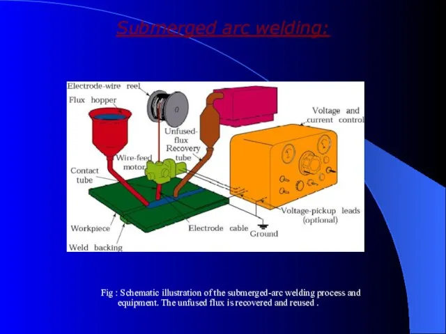
Слайд 17Submerged arc welding:
Fig : Schematic illustration of the submerged-arc welding process and
Submerged arc welding:
Fig : Schematic illustration of the submerged-arc welding process and
Слайд 18Submerged arc welding:
Weld arc is shielded by a granular flux ,consisting of
Submerged arc welding:
Weld arc is shielded by a granular flux ,consisting of
Слайд 19Gas metal arc welding:
GMAW is a metal inert gas welding (MIG)
Weld area
Gas metal arc welding:
GMAW is a metal inert gas welding (MIG)
Weld area
Слайд 20Gas Metal-Arc Welding
Fig : Schematic illustration of the gas metal-arc welding process,
Gas Metal-Arc Welding
Fig : Schematic illustration of the gas metal-arc welding process,
Слайд 21Equipment used in Metal-Arc Welding Operations
Fig : Basic equipment used in gas
Equipment used in Metal-Arc Welding Operations
Fig : Basic equipment used in gas
Слайд 22Flux–cored Arc – Welding
Flux cored arc welding is similar to a gas
Flux–cored Arc – Welding
Flux cored arc welding is similar to a gas
Слайд 23Flux-Cored Arc Welding
Fig : Schematic illustration of the flux-cored arc-welding process. This
Flux-Cored Arc Welding
Fig : Schematic illustration of the flux-cored arc-welding process. This
Слайд 24Electro gas Welding :
EGW is welding the edges of sections vertically in
Electro gas Welding :
EGW is welding the edges of sections vertically in
Слайд 25Electrogas Welding
Fig : Schematic illustration of the electrogas welding process
Electrogas Welding
Fig : Schematic illustration of the electrogas welding process
Слайд 26Electroslag Welding:
Similar to Electro gas welding
Difference is Arc is started between electrode
Electroslag Welding:
Similar to Electro gas welding
Difference is Arc is started between electrode
Слайд 27Equipment used in Electroslag welding
Fig : Equipment used for electroslag welding
Equipment used in Electroslag welding
Fig : Equipment used for electroslag welding
Слайд 28Solid-State Welding Processes
Solid-State Welding Processes
Слайд 29Cold Welding
Pressure is applied to the workpieces through dies or rolls
Preferably both
Cold Welding
Pressure is applied to the workpieces through dies or rolls
Preferably both
Слайд 30Ultrasonic Welding
Surfaces of the two components are subjected to a static forces
Ultrasonic Welding
Surfaces of the two components are subjected to a static forces
Слайд 31Friction Welding
Developed in the 1940’s
Parts are circular in shape
Can be used to
Friction Welding
Developed in the 1940’s
Parts are circular in shape
Can be used to
Слайд 32Process can be fully automated
Can weld solid steel bars up to 250mm
Process can be fully automated
Can weld solid steel bars up to 250mm
Слайд 33Inertia Friction Welding
Modification of Friction Welding
Energy is supplied by a fly wheel
The
Inertia Friction Welding
Modification of Friction Welding
Energy is supplied by a fly wheel
The
Слайд 34Linear Friction Welding
Parts are joined by a linear reciprocating motion
Parts do not
Linear Friction Welding
Parts are joined by a linear reciprocating motion
Parts do not
Слайд 35Friction Stir Welding (FSW)
New Process for welding aerospace metals
Research is being directed
Friction Stir Welding (FSW)
New Process for welding aerospace metals
Research is being directed
Слайд 36Resistance Welding
Developed in the early 1900’s
A process in which the heat required
Resistance Welding
Developed in the early 1900’s
A process in which the heat required
Слайд 37Resistance Spot Welding
RSW uses the tips of two opposing solid cylindrical electrodes
Pressure
Resistance Spot Welding
RSW uses the tips of two opposing solid cylindrical electrodes
Pressure
Слайд 38Surfaces should be clean
Accurate control of and timing of electric current and
Surfaces should be clean
Accurate control of and timing of electric current and
Слайд 39Resistance Seam Welding
RSEM is modification of spot welding wherein the electrodes are
Resistance Seam Welding
RSEM is modification of spot welding wherein the electrodes are
Слайд 40Resistance Projection Welding
RPW is developed by introducing high electrical resistance at a
Resistance Projection Welding
RPW is developed by introducing high electrical resistance at a
Слайд 41The electrodes exert pressure to compress the projections
Nuts and bolts can be
The electrodes exert pressure to compress the projections
Nuts and bolts can be
Слайд 42Flash Welding
Heat is generated from the arc as the ends as the
Flash Welding
Heat is generated from the arc as the ends as the
Слайд 43Stud Welding
Small part or a threaded rod or hanger serves as a
Stud Welding
Small part or a threaded rod or hanger serves as a
 УРОК 5 Понедельник 26 июля 2010 Начало в 15.55 по московском времени 1. - презентация
 Понедельник - встреча Масленницы
 Котлеты по-киевски
 КАЛЕНДАРЬЗНАМЕНАТЕЛЬНЫХ ДАТ (НА МАРТ 2012 ГОДА)
 Архитектура ИКТ – организационная, юридическая и технологическая модель взаимодействий
 ПРИЧИНЫ ДЛЯ ТОГО, ЧТОБЫ ИМЕТЬ НЕЗАВИСИМЫЙ РЕГУЛИРУЮЩИЙ ОРГАН: НЕБОЛЬШОЙ ОТДЫХ
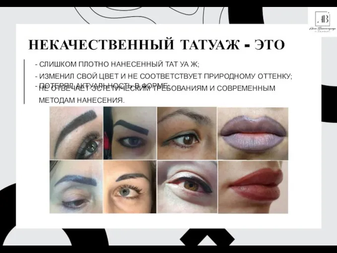 Некачественный татуаж. Способы исправления
 Русская лексика с точки зрения сферы ее употребления
 Выполнение домашнего задания
 Световой пучок и световой луч.Образование тени и полутени.
 О внесении изменений в номенклатуру должностей педагогических работников организаций образовательной деятельности
 Презентация ДСТИ+ (3)
 MadameTussaud’s Музей Восковых фигур Мадам Тюссо
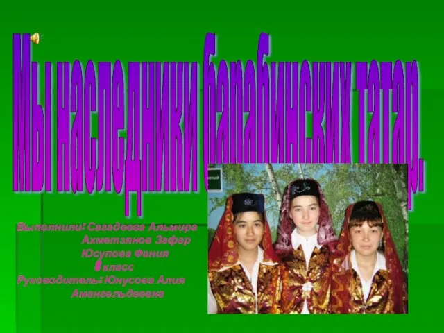 Мы наследники барабинских татар
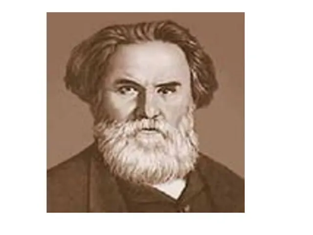 Короленко "В дурном обществе"
 Межличностная коммуникация
 eBook Academic Collection
 Ознакомление с окружающим миром: зимующие птицы нашего края
 Выразительные словообразовательные средства Учитель Омельчук Е.И.
 Презентация на тему Загадки по ПДД
  Я – талант, мы все – таланты!. Проект о спортсменах. Выпуск 1
 Требования к оформлению мультимедийных презентаций
 Коммуникативные сервисы электронных библиотек ВУЗов
 Любовь Шамовна Вассерман
 Залилов (Джалиль) Муса Мустафович 1906 – 1944 г
 Школа России
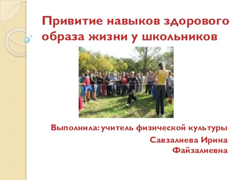 Привитие навыков здорового образа жизни у школьников
 Организация маркетинга в вузе