- Technical English. Vocabulary

Содержание
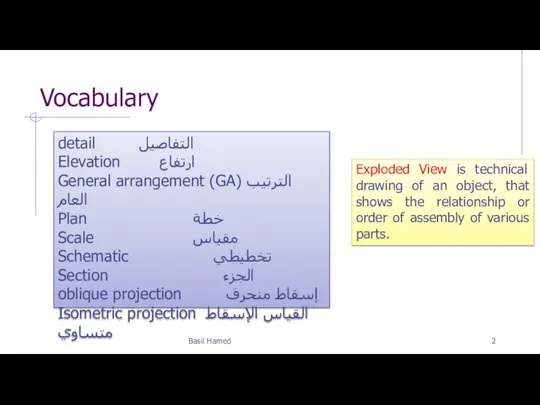
- 2. Vocabulary Basil Hamed detail التفاصيل Elevation ارتفاع General arrangement (GA) الترتيب العام Plan خطة Scale مقياس
- 3. Outline Drawing types and scales Types of views used on drawings
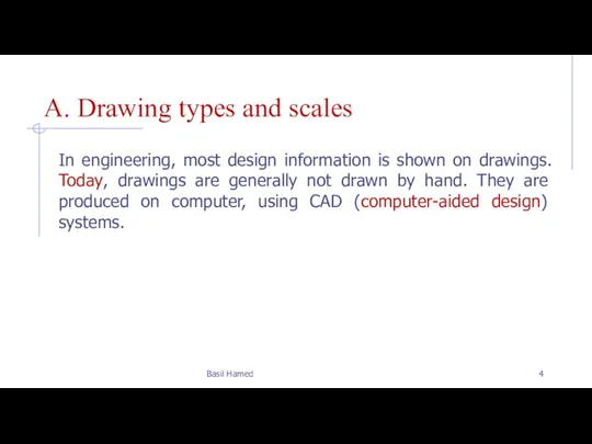
- 4. A. Drawing types and scales In engineering, most design information is shown on drawings. Today, drawings
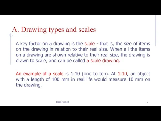
- 5. A. Drawing types and scales A key factor on a drawing is the scale - that
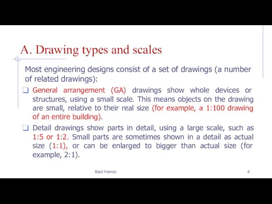
- 6. A. Drawing types and scales Most engineering designs consist of a set of drawings (a number
- 7. A. Drawing types and scales For electrical circuits, and pipe and duct networks, it is helpful
- 8. B. Types of views used on drawings Technicians are discussing different views shown on drawings (looking
- 9. B. Types of views used on drawings There should be a section Through the pipe, showing
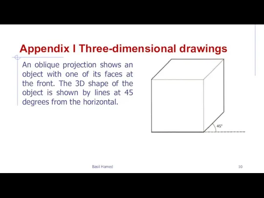
- 10. Appendix I Three-dimensional drawings An oblique projection shows an object with one of its faces at
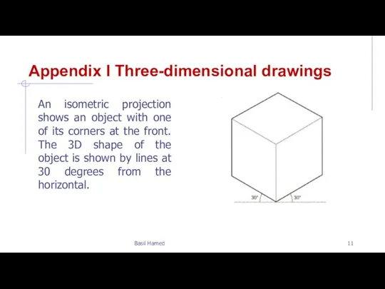
- 11. Appendix I Three-dimensional drawings An isometric projection shows an object with one of its corners at
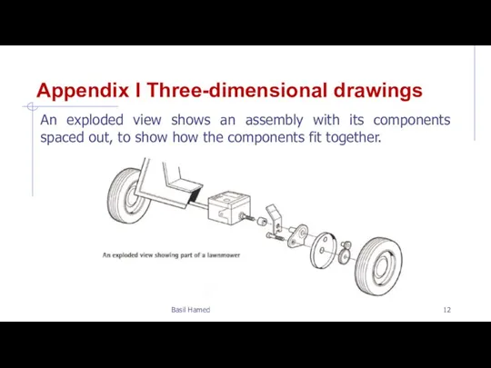
- 12. Appendix I Three-dimensional drawings An exploded view shows an assembly with its components spaced out, to
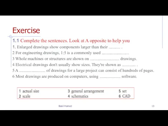
- 13. Exercise 1.1 Complete the sentences. Look at A opposite to help you 1. Enlarged drawings show
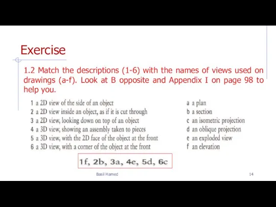
- 14. Exercise 1.2 Match the descriptions (1-6) with the names of views used on drawings (a-f). Look
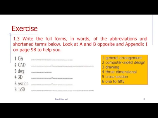
- 15. Exercise 1.3 Write the full forms, in words, of the abbreviations and shortened terms below. Look
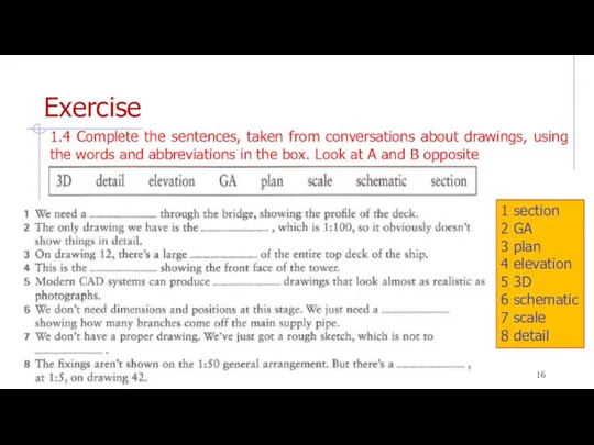
- 16. Exercise 1.4 Complete the sentences, taken from conversations about drawings, using the words and abbreviations in
- 18. Скачать презентацию
Слайд 2Vocabulary
Basil Hamed
detail التفاصيل
Elevation ارتفاع
General arrangement (GA) الترتيب العام
Plan خطة
Scale مقياس
Schematic تخطيطي
Section الجزء
oblique
Vocabulary
Basil Hamed
detail التفاصيل
Elevation ارتفاع
General arrangement (GA) الترتيب العام
Plan خطة
Scale مقياس
Schematic تخطيطي
Section الجزء
oblique
Слайд 3Outline
Drawing types and scales
Types of views used on drawings
Outline
Drawing types and scales
Types of views used on drawings
Слайд 4A. Drawing types and scales
In engineering, most design information is shown on
A. Drawing types and scales
In engineering, most design information is shown on
Слайд 5A. Drawing types and scales
A key factor on a drawing is the
A. Drawing types and scales
A key factor on a drawing is the
Слайд 6A. Drawing types and scales
Most engineering designs consist of a set of
A. Drawing types and scales
Most engineering designs consist of a set of
Слайд 7A. Drawing types and scales
For electrical circuits, and pipe and duct networks,
A. Drawing types and scales
For electrical circuits, and pipe and duct networks,
Слайд 8B. Types of views used on drawings
Technicians are discussing different views shown
B. Types of views used on drawings
Technicians are discussing different views shown
Слайд 9B. Types of views used on drawings
There should be a section Through
B. Types of views used on drawings
There should be a section Through
Слайд 10Appendix I Three-dimensional drawings
An oblique projection shows an object with one of
Appendix I Three-dimensional drawings
An oblique projection shows an object with one of
Слайд 11Appendix I Three-dimensional drawings
An isometric projection shows an object with one of
Appendix I Three-dimensional drawings
An isometric projection shows an object with one of
Слайд 12Appendix I Three-dimensional drawings
An exploded view shows an assembly with its components
Appendix I Three-dimensional drawings
An exploded view shows an assembly with its components
Слайд 13Exercise
1.1 Complete the sentences. Look at A opposite to help you
1. Enlarged
Exercise
1.1 Complete the sentences. Look at A opposite to help you
1. Enlarged
Слайд 14Exercise
1.2 Match the descriptions (1-6) with the names of views used on
Exercise
1.2 Match the descriptions (1-6) with the names of views used on
Слайд 15Exercise
1.3 Write the full forms, in words, of the abbreviations and shortened
Exercise
1.3 Write the full forms, in words, of the abbreviations and shortened
Слайд 16Exercise
1.4 Complete the sentences, taken from conversations about drawings, using the words
Exercise
1.4 Complete the sentences, taken from conversations about drawings, using the words
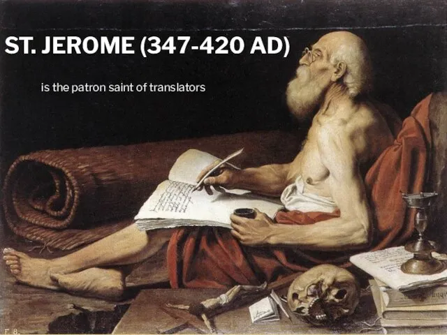 St. Jerome (347-420 AD) is the patron saint of translators
 What's this
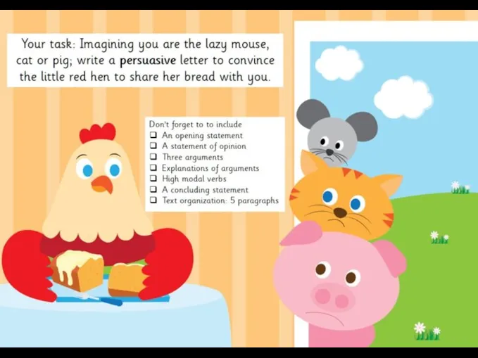 The little red hen. Writing activity
 Письменное сложение трёхзначных чисел
 My style
 Birthday. Bingo
 Презентация к уроку английского языка "Polar Bear" -
  Grammar football. Present simple
 B-girl Nadya Da Funky Style Crew
 The best of all possible world's. Australia
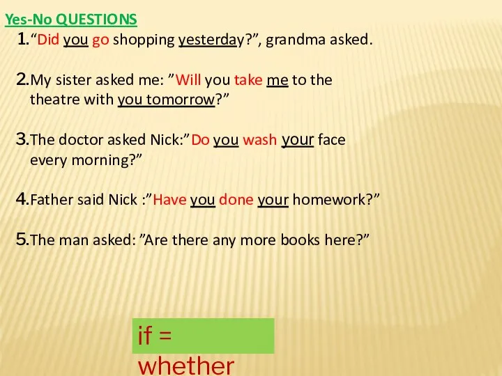 Yes-No QUESTIONS
 Advantages and Disadvantages of living in the modern city and in the country Учитель иностранных языков МОУ «Дашковская СОШ» Рудик Анастасия Сергеевна
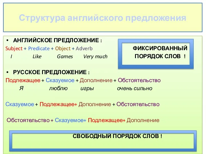 Структура английского предложения
 Презентация на тему ВОПРОСИТЕЛЬНЫЕ ПРЕДЛОЖЕНИЯ
  Жиілік үстеулер
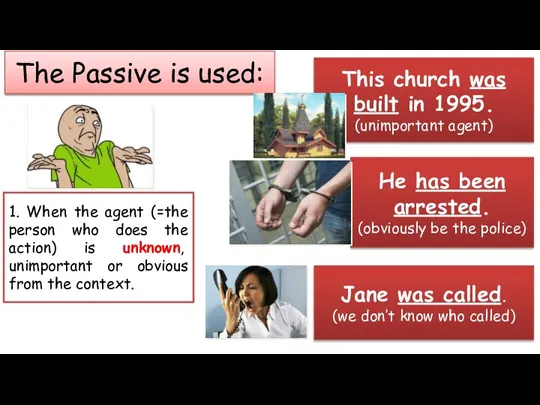 The Passive is used
 Масс-медиа
 Subject Link. Lesson 16
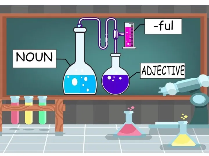 Word build
 Degrees of comparison
 Airport
 Программа изучения английского языка в East-West Bridge Centre
 Контрольная работа и задания
 Time wheel
 Who wants to be a millioner
 Weather
 Презентация на тему Иностранные языки в моей жизни
  Suggested Taxonomy of Contrastive Studies by Tomas Krzeszowski