- Object-Oriented Programming and Java

Содержание
- 2. OOP - Rovaniemi University of Applied Sciences Course Contents Part I: Object-Oriented Concepts and Principles Part
- 3. OOP - Rovaniemi University of Applied Sciences Unified Modelling Language Several different notations for describing object-oriented
- 4. OOP - Rovaniemi University of Applied Sciences UML Inputs Meyer Pre- and post- conditions
- 5. OOP - Rovaniemi University of Applied Sciences Evolution of the UML The first public draft (version
- 6. OOP - Rovaniemi University of Applied Sciences Object-Oriented Analysis The intent of OOA is to define
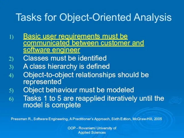
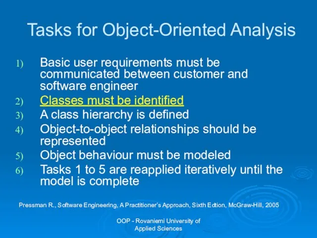
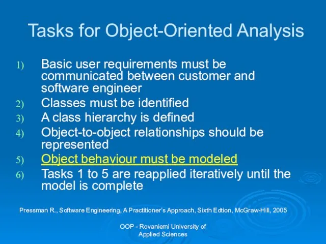
- 7. OOP - Rovaniemi University of Applied Sciences Tasks for Object-Oriented Analysis Basic user requirements must be
- 8. OOP - Rovaniemi University of Applied Sciences What Is a Use Case? Formal description: Use case
- 9. OOP - Rovaniemi University of Applied Sciences What Is an Actor? Informal description: actors are types
- 10. OOP - Rovaniemi University of Applied Sciences Use Case Diagrams Shows actors and use cases. Shows
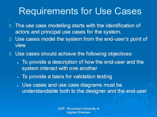
- 11. OOP - Rovaniemi University of Applied Sciences Requirements for Use Cases The use case modelling starts
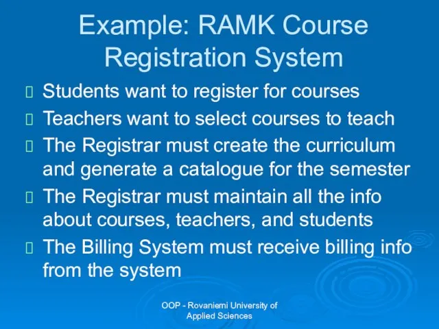
- 12. OOP - Rovaniemi University of Applied Sciences Example: RAMK Course Registration System Students want to register
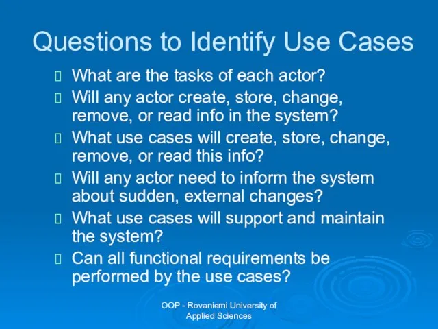
- 13. OOP - Rovaniemi University of Applied Sciences Questions to Identify Use Cases What are the tasks
- 14. OOP - Rovaniemi University of Applied Sciences Example: RAMK Course Registration System The following use cases
- 15. OOP - Rovaniemi University of Applied Sciences RAMK Course Registration System Register for courses
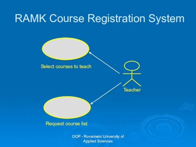
- 16. OOP - Rovaniemi University of Applied Sciences RAMK Course Registration System Select courses to teach Request
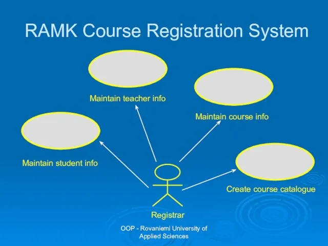
- 17. OOP - Rovaniemi University of Applied Sciences RAMK Course Registration System Maintain student info Maintain teacher
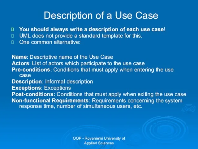
- 18. OOP - Rovaniemi University of Applied Sciences Description of a Use Case You should always write
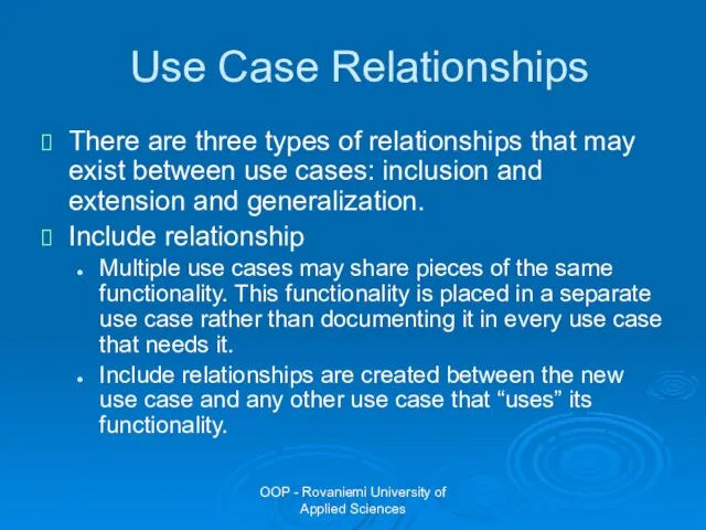
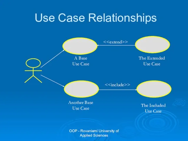
- 19. OOP - Rovaniemi University of Applied Sciences Use Case Relationships There are three types of relationships
- 20. OOP - Rovaniemi University of Applied Sciences Use Case Relationships E.g., each use case starts with
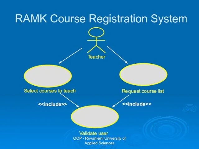
- 21. OOP - Rovaniemi University of Applied Sciences RAMK Course Registration System Select courses to teach Request
- 22. OOP - Rovaniemi University of Applied Sciences Use Case Relationships
- 23. OOP - Rovaniemi University of Applied Sciences Pay overdraft fee Pay invoice > Accounting System Perform
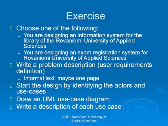
- 24. OOP - Rovaniemi University of Applied Sciences Exercise Choose one of the following: You are designing
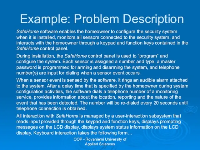
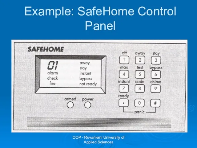
- 25. OOP - Rovaniemi University of Applied Sciences Example: Problem Description SafeHome software enables the homeowner to
- 26. OOP - Rovaniemi University of Applied Sciences Example: SafeHome Control Panel
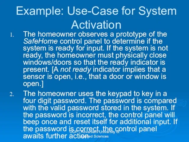
- 27. OOP - Rovaniemi University of Applied Sciences Example: Use-Case for System Activation The homeowner observes a
- 28. OOP - Rovaniemi University of Applied Sciences Example: Use-Case for System Activation (continued) The homeowner selects
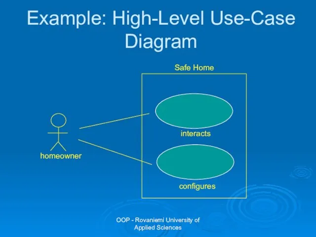
- 29. OOP - Rovaniemi University of Applied Sciences Example: High-Level Use-Case Diagram Safe Home interacts configures
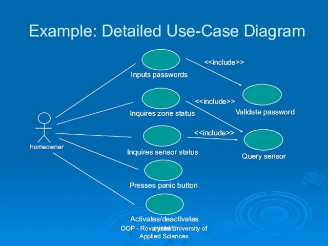
- 30. OOP - Rovaniemi University of Applied Sciences Example: Detailed Use-Case Diagram Inputs passwords > > >
- 31. OOP - Rovaniemi University of Applied Sciences Tasks for Object-Oriented Analysis Basic user requirements must be
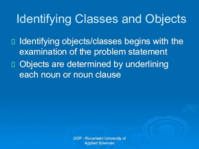
- 32. OOP - Rovaniemi University of Applied Sciences Identifying Classes and Objects Identifying objects/classes begins with the
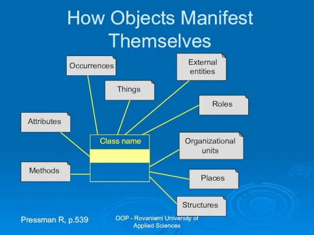
- 33. OOP - Rovaniemi University of Applied Sciences How Objects Manifest Themselves Pressman R, p.539
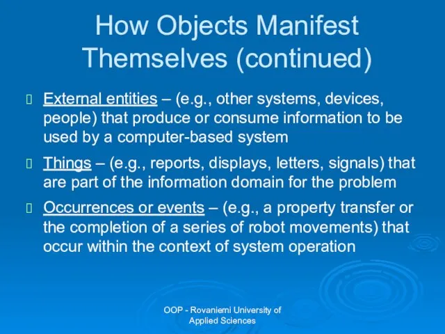
- 34. OOP - Rovaniemi University of Applied Sciences How Objects Manifest Themselves (continued) External entities – (e.g.,
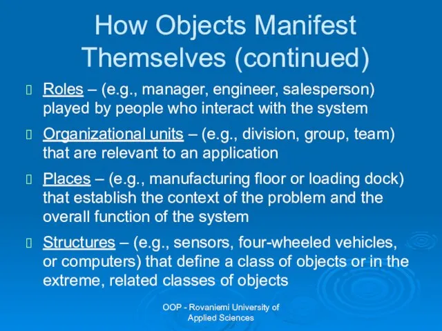
- 35. OOP - Rovaniemi University of Applied Sciences How Objects Manifest Themselves (continued) Roles – (e.g., manager,
- 36. OOP - Rovaniemi University of Applied Sciences Example: Problem Description SafeHome software enables the homeowner to
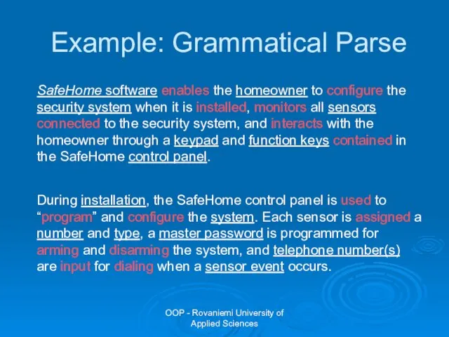
- 37. OOP - Rovaniemi University of Applied Sciences Example: Grammatical Parse SafeHome software enables the homeowner to
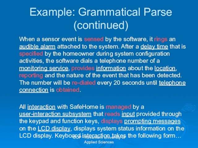
- 38. OOP - Rovaniemi University of Applied Sciences Example: Grammatical Parse (continued) When a sensor event is
- 39. OOP - Rovaniemi University of Applied Sciences Example: Potential Classes
- 40. OOP - Rovaniemi University of Applied Sciences Group work Analyze the problem description and make a
- 41. OOP - Rovaniemi University of Applied Sciences Selection Characteristics Coad and Yourdon suggest 6 selection characteristics
- 42. OOP - Rovaniemi University of Applied Sciences Selection Characteristics Multiple attributes – during requirement analysis, the
- 43. OOP - Rovaniemi University of Applied Sciences Selection Characteristics Common operations – a set of operations
- 44. OOP - Rovaniemi University of Applied Sciences Example: Evaluation of Potential Classes
- 45. OOP - Rovaniemi University of Applied Sciences Group Work Analyze potential classes on your list according
- 46. OOP - Rovaniemi University of Applied Sciences Specifying Attributes Attributes describe a class that has been
- 47. OOP - Rovaniemi University of Applied Sciences Example: Specifying Attributes for “System” Object sensor information =
- 48. OOP - Rovaniemi University of Applied Sciences Defining Methods Methods i.e. operations define the behaviour of
- 49. OOP - Rovaniemi University of Applied Sciences Defining Methods Select the methods that reasonably belong to
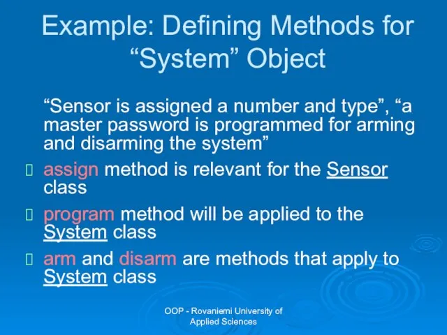
- 50. OOP - Rovaniemi University of Applied Sciences Example: Defining Methods for “System” Object “Sensor is assigned
- 51. OOP - Rovaniemi University of Applied Sciences Finalizing the Object Definition The definition of methods is
- 52. OOP - Rovaniemi University of Applied Sciences Example: Finalizing the “System” Object program() display() reset() query()
- 53. OOP - Rovaniemi University of Applied Sciences Group Work Define attributes and methods for the classes,
- 54. OOP - Rovaniemi University of Applied Sciences Tasks for Object-Oriented Analysis Basic user requirements must be
- 55. OOP - Rovaniemi University of Applied Sciences UML Class Diagram Most important UML diagram Can easily
- 56. OOP - Rovaniemi University of Applied Sciences Example of a Class in an UML Class Diagram
- 57. OOP - Rovaniemi University of Applied Sciences Example of an UML Class Diagram
- 58. OOP - Rovaniemi University of Applied Sciences Class Relationship Categories Generalization Inheritance or realization Aggregation Special
- 59. OOP - Rovaniemi University of Applied Sciences Generalization (Inheritance) Classes may be arranged in a class
- 60. OOP - Rovaniemi University of Applied Sciences Generalization (Inheritance)
- 61. OOP - Rovaniemi University of Applied Sciences Realization (Implementation) of an Interface A class implements the
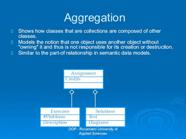
- 62. OOP - Rovaniemi University of Applied Sciences Aggregation Shows how classes that are collections are composed
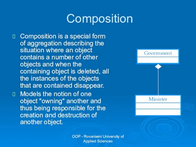
- 63. OOP - Rovaniemi University of Applied Sciences Composition Composition is a special form of aggregation describing
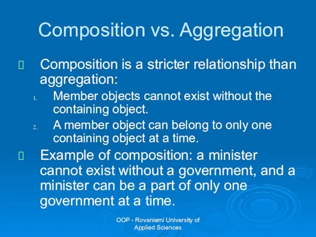
- 64. OOP - Rovaniemi University of Applied Sciences Composition vs. Aggregation Composition is a stricter relationship than
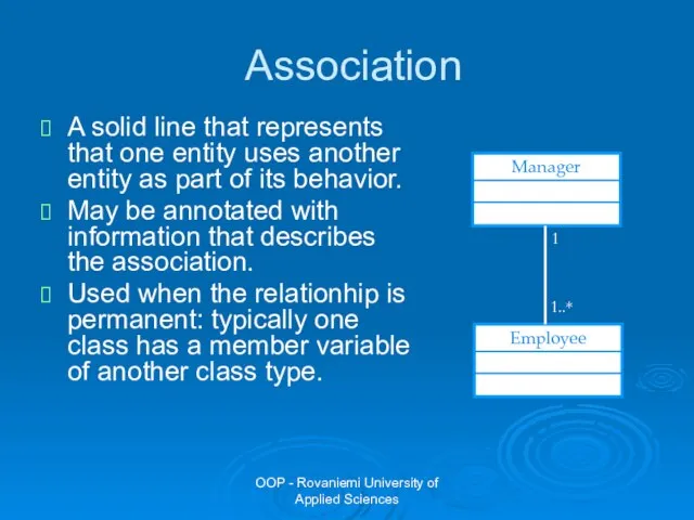
- 65. OOP - Rovaniemi University of Applied Sciences Association A solid line that represents that one entity
- 66. OOP - Rovaniemi University of Applied Sciences Attributes and Associations Attributes and associations are exchangeable! When
- 67. OOP - Rovaniemi University of Applied Sciences Dependency A dotted line with an open arrowhead that
- 68. OOP - Rovaniemi University of Applied Sciences Qualified Association University Student - name: string - address:
- 69. OOP - Rovaniemi University of Applied Sciences Association Aggregation Composition Person owns Car Workstation Cat Tail
- 70. OOP - Rovaniemi University of Applied Sciences > Window {abstract, author = KK status = tested}
- 71. OOP - Rovaniemi University of Applied Sciences Sidetrack 1: Derived Attributes Two areas where data modeling
- 72. OOP - Rovaniemi University of Applied Sciences Sidetrack 2: Code Values A coded value uses one
- 73. OOP - Rovaniemi University of Applied Sciences Group Work Draw an UML class diagram of the
- 74. OOP - Rovaniemi University of Applied Sciences Tasks for Object-Oriented Analysis Basic user requirements must be
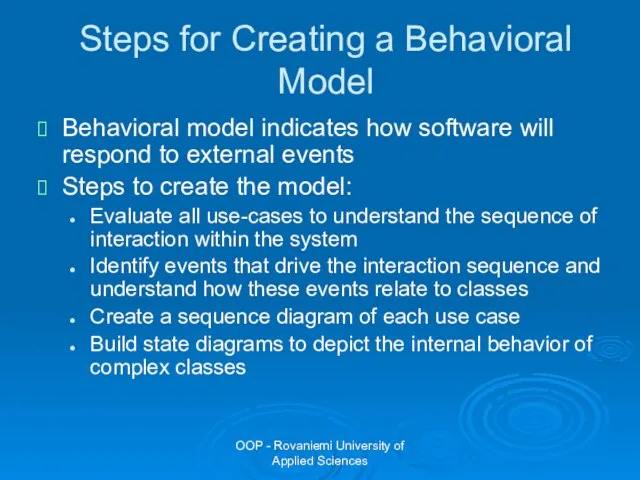
- 75. OOP - Rovaniemi University of Applied Sciences Steps for Creating a Behavioral Model Behavioral model indicates
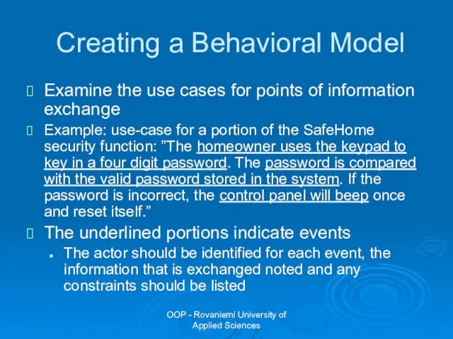
- 76. OOP - Rovaniemi University of Applied Sciences Creating a Behavioral Model Examine the use cases for
- 77. OOP - Rovaniemi University of Applied Sciences Creating a Behavioral Model Once all events have been
- 78. OOP - Rovaniemi University of Applied Sciences SET ALARM M H :Ringer Switch on :Light Press
- 79. OOP - Rovaniemi University of Applied Sciences Sequence Diagram Notation An object is shown as a
- 80. OOP - Rovaniemi University of Applied Sciences Sequence Diagram Notation You can show a self-call, a
- 81. OOP - Rovaniemi University of Applied Sciences Sequence Diagram Notation
- 82. OOP - Rovaniemi University of Applied Sciences Asyncronous Messages in Sequence Diagram The half-arrowheads indicate an
- 83. OOP - Rovaniemi University of Applied Sciences Object Creation and Deletion in Sequence Diagram If an
- 84. OOP - Rovaniemi University of Applied Sciences Group Work Choose one of the use cases you
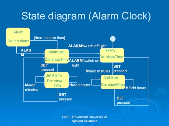
- 85. OOP - Rovaniemi University of Applied Sciences SET pressed Do: showTime Ready M/add minutes H/add hours
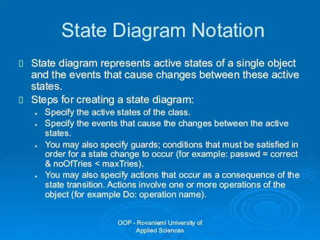
- 86. OOP - Rovaniemi University of Applied Sciences State Diagram Notation State diagram represents active states of
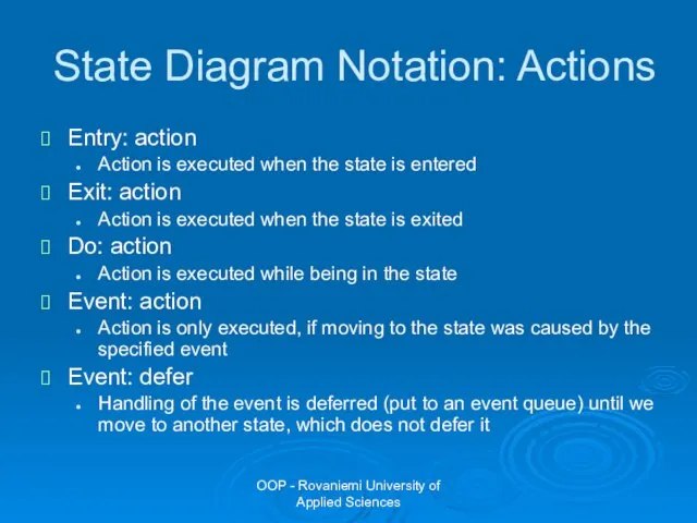
- 87. OOP - Rovaniemi University of Applied Sciences State Diagram Notation: Actions Entry: action Action is executed
- 88. OOP - Rovaniemi University of Applied Sciences Summary Sequence diagram shows typical interactions between domain objects.
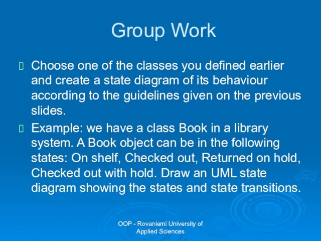
- 89. OOP - Rovaniemi University of Applied Sciences Group Work Choose one of the classes you defined
- 91. Скачать презентацию
Слайд 2OOP - Rovaniemi University of Applied Sciences
Course Contents
Part I: Object-Oriented Concepts and
OOP - Rovaniemi University of Applied Sciences
Course Contents
Part I: Object-Oriented Concepts and
Слайд 3OOP - Rovaniemi University of Applied Sciences
Unified Modelling Language
Several different notations for
OOP - Rovaniemi University of Applied Sciences
Unified Modelling Language
Several different notations for
Слайд 4OOP - Rovaniemi University of Applied Sciences
UML Inputs
Meyer
Pre- and post- conditions
OOP - Rovaniemi University of Applied Sciences
UML Inputs
Meyer
Pre- and post- conditions

Слайд 5OOP - Rovaniemi University of Applied Sciences
Evolution of the UML
The first
OOP - Rovaniemi University of Applied Sciences
Evolution of the UML
The first
Слайд 6OOP - Rovaniemi University of Applied Sciences
Object-Oriented Analysis
The intent of OOA is
OOP - Rovaniemi University of Applied Sciences
Object-Oriented Analysis
The intent of OOA is
Слайд 7OOP - Rovaniemi University of Applied Sciences
Tasks for Object-Oriented Analysis
Basic user requirements
OOP - Rovaniemi University of Applied Sciences
Tasks for Object-Oriented Analysis
Basic user requirements
Слайд 8OOP - Rovaniemi University of Applied Sciences
What Is a Use Case?
Formal description:
OOP - Rovaniemi University of Applied Sciences
What Is a Use Case?
Formal description:
Слайд 9OOP - Rovaniemi University of Applied Sciences
What Is an Actor?
Informal description: actors
OOP - Rovaniemi University of Applied Sciences
What Is an Actor?
Informal description: actors
Слайд 10OOP - Rovaniemi University of Applied Sciences
Use Case Diagrams
Shows actors and use
OOP - Rovaniemi University of Applied Sciences
Use Case Diagrams
Shows actors and use
Слайд 11OOP - Rovaniemi University of Applied Sciences
Requirements for Use Cases
The use case
OOP - Rovaniemi University of Applied Sciences
Requirements for Use Cases
The use case
Слайд 12OOP - Rovaniemi University of Applied Sciences
Example: RAMK Course Registration System
Students want
OOP - Rovaniemi University of Applied Sciences
Example: RAMK Course Registration System
Students want
Слайд 13OOP - Rovaniemi University of Applied Sciences
Questions to Identify Use Cases
What are
OOP - Rovaniemi University of Applied Sciences
Questions to Identify Use Cases
What are
Слайд 14OOP - Rovaniemi University of Applied Sciences
Example: RAMK Course Registration System
The following
OOP - Rovaniemi University of Applied Sciences
Example: RAMK Course Registration System
The following

Слайд 15OOP - Rovaniemi University of Applied Sciences
RAMK Course Registration System
Register for courses
OOP - Rovaniemi University of Applied Sciences
RAMK Course Registration System
Register for courses

Слайд 16OOP - Rovaniemi University of Applied Sciences
RAMK Course Registration System
Select courses to
OOP - Rovaniemi University of Applied Sciences
RAMK Course Registration System
Select courses to
Слайд 17OOP - Rovaniemi University of Applied Sciences
RAMK Course Registration System
Maintain student info
Maintain
OOP - Rovaniemi University of Applied Sciences
RAMK Course Registration System
Maintain student info
Maintain
Слайд 18OOP - Rovaniemi University of Applied Sciences
Description of a Use Case
You should
OOP - Rovaniemi University of Applied Sciences
Description of a Use Case
You should
Слайд 19OOP - Rovaniemi University of Applied Sciences
Use Case Relationships
There are three types
OOP - Rovaniemi University of Applied Sciences
Use Case Relationships
There are three types
Слайд 20OOP - Rovaniemi University of Applied Sciences
Use Case Relationships
E.g., each use case
OOP - Rovaniemi University of Applied Sciences
Use Case Relationships
E.g., each use case

Слайд 21OOP - Rovaniemi University of Applied Sciences
RAMK Course Registration System
Select courses to
OOP - Rovaniemi University of Applied Sciences
RAMK Course Registration System
Select courses to
Слайд 22OOP - Rovaniemi University of Applied Sciences
Use Case Relationships
OOP - Rovaniemi University of Applied Sciences
Use Case Relationships
Слайд 23OOP - Rovaniemi University of Applied Sciences
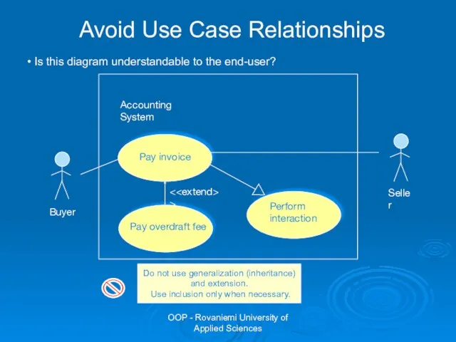
Pay overdraft fee
Pay invoice
<>
Accounting System
Perform
interaction
Buyer
Seller
Avoid Use
OOP - Rovaniemi University of Applied Sciences
Pay overdraft fee
Pay invoice
< Accounting System Perform Buyer Seller Avoid Use
interaction
Слайд 24OOP - Rovaniemi University of Applied Sciences
Exercise
Choose one of the following:
You are
OOP - Rovaniemi University of Applied Sciences
Exercise
Choose one of the following:
You are
Слайд 25OOP - Rovaniemi University of Applied Sciences
Example: Problem Description
SafeHome software enables the
OOP - Rovaniemi University of Applied Sciences
Example: Problem Description
SafeHome software enables the
Слайд 26OOP - Rovaniemi University of Applied Sciences
Example: SafeHome Control Panel
OOP - Rovaniemi University of Applied Sciences
Example: SafeHome Control Panel
Слайд 27OOP - Rovaniemi University of Applied Sciences
Example: Use-Case for System Activation
The homeowner
OOP - Rovaniemi University of Applied Sciences
Example: Use-Case for System Activation
The homeowner
Слайд 28OOP - Rovaniemi University of Applied Sciences
Example: Use-Case for System Activation (continued)
The
OOP - Rovaniemi University of Applied Sciences
Example: Use-Case for System Activation (continued)
The

Слайд 29OOP - Rovaniemi University of Applied Sciences
Example: High-Level Use-Case Diagram
Safe Home
interacts
configures
OOP - Rovaniemi University of Applied Sciences
Example: High-Level Use-Case Diagram
Safe Home
interacts
configures
Слайд 30OOP - Rovaniemi University of Applied Sciences
Example: Detailed Use-Case Diagram
Inputs passwords
<>
<>
<>
OOP - Rovaniemi University of Applied Sciences
Example: Detailed Use-Case Diagram
Inputs passwords
< < <
Слайд 31OOP - Rovaniemi University of Applied Sciences
Tasks for Object-Oriented Analysis
Basic user requirements
OOP - Rovaniemi University of Applied Sciences
Tasks for Object-Oriented Analysis
Basic user requirements
Слайд 32OOP - Rovaniemi University of Applied Sciences
Identifying Classes and Objects
Identifying objects/classes begins
OOP - Rovaniemi University of Applied Sciences
Identifying Classes and Objects
Identifying objects/classes begins
Слайд 33OOP - Rovaniemi University of Applied Sciences
How Objects Manifest Themselves
Pressman R, p.539
OOP - Rovaniemi University of Applied Sciences
How Objects Manifest Themselves
Pressman R, p.539
Слайд 34OOP - Rovaniemi University of Applied Sciences
How Objects Manifest Themselves (continued)
External entities
OOP - Rovaniemi University of Applied Sciences
How Objects Manifest Themselves (continued)
External entities
Слайд 35OOP - Rovaniemi University of Applied Sciences
How Objects Manifest Themselves (continued)
Roles –
OOP - Rovaniemi University of Applied Sciences
How Objects Manifest Themselves (continued)
Roles –
Слайд 36OOP - Rovaniemi University of Applied Sciences
Example: Problem Description
SafeHome software enables the
OOP - Rovaniemi University of Applied Sciences
Example: Problem Description
SafeHome software enables the

Слайд 37OOP - Rovaniemi University of Applied Sciences
Example: Grammatical Parse
SafeHome software enables the
OOP - Rovaniemi University of Applied Sciences
Example: Grammatical Parse
SafeHome software enables the
Слайд 38OOP - Rovaniemi University of Applied Sciences
Example: Grammatical Parse (continued)
When a sensor
OOP - Rovaniemi University of Applied Sciences
Example: Grammatical Parse (continued)
When a sensor
Слайд 39OOP - Rovaniemi University of Applied Sciences
Example: Potential Classes
OOP - Rovaniemi University of Applied Sciences
Example: Potential Classes

Слайд 40OOP - Rovaniemi University of Applied Sciences
Group work
Analyze the problem description and
OOP - Rovaniemi University of Applied Sciences
Group work
Analyze the problem description and
Слайд 41OOP - Rovaniemi University of Applied Sciences
Selection Characteristics
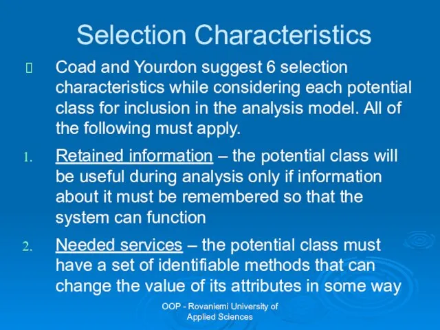
Coad and Yourdon suggest 6
OOP - Rovaniemi University of Applied Sciences
Selection Characteristics
Coad and Yourdon suggest 6
Слайд 42OOP - Rovaniemi University of Applied Sciences
Selection Characteristics
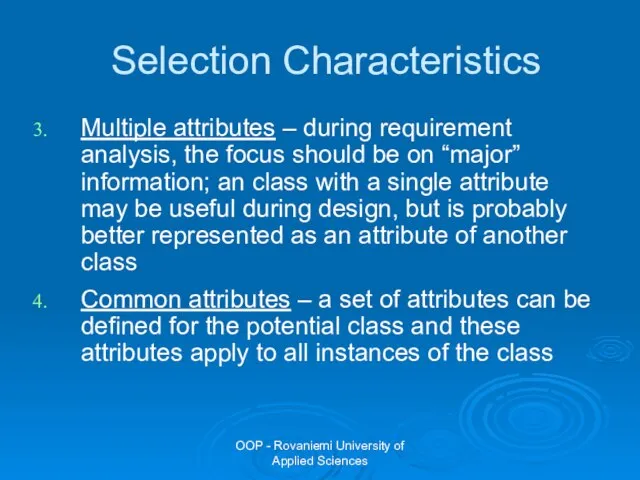
Multiple attributes – during requirement
OOP - Rovaniemi University of Applied Sciences
Selection Characteristics
Multiple attributes – during requirement
Слайд 43OOP - Rovaniemi University of Applied Sciences
Selection Characteristics
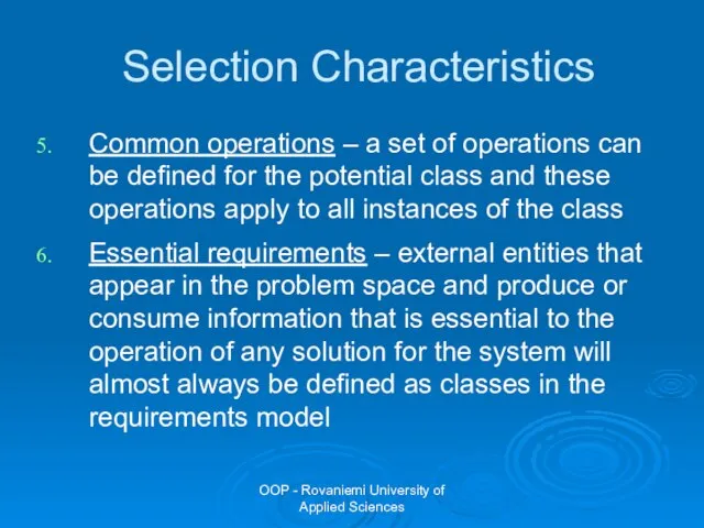
Common operations – a set
OOP - Rovaniemi University of Applied Sciences
Selection Characteristics
Common operations – a set
Слайд 44OOP - Rovaniemi University of Applied Sciences
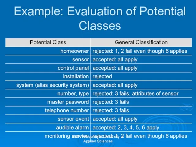
Example: Evaluation of Potential Classes
OOP - Rovaniemi University of Applied Sciences
Example: Evaluation of Potential Classes
Слайд 45OOP - Rovaniemi University of Applied Sciences
Group Work
Analyze potential classes on your
OOP - Rovaniemi University of Applied Sciences
Group Work
Analyze potential classes on your
Слайд 46OOP - Rovaniemi University of Applied Sciences
Specifying Attributes
Attributes describe a class that
OOP - Rovaniemi University of Applied Sciences
Specifying Attributes
Attributes describe a class that
Слайд 47OOP - Rovaniemi University of Applied Sciences
Example: Specifying Attributes for “System” Object
sensor
OOP - Rovaniemi University of Applied Sciences
Example: Specifying Attributes for “System” Object
sensor

Слайд 48OOP - Rovaniemi University of Applied Sciences
Defining Methods
Methods i.e. operations define the
OOP - Rovaniemi University of Applied Sciences
Defining Methods
Methods i.e. operations define the

Слайд 49OOP - Rovaniemi University of Applied Sciences
Defining Methods
Select the methods that reasonably
OOP - Rovaniemi University of Applied Sciences
Defining Methods
Select the methods that reasonably
Слайд 50OOP - Rovaniemi University of Applied Sciences
Example: Defining Methods for “System” Object
“Sensor
OOP - Rovaniemi University of Applied Sciences
Example: Defining Methods for “System” Object
“Sensor
Слайд 51OOP - Rovaniemi University of Applied Sciences
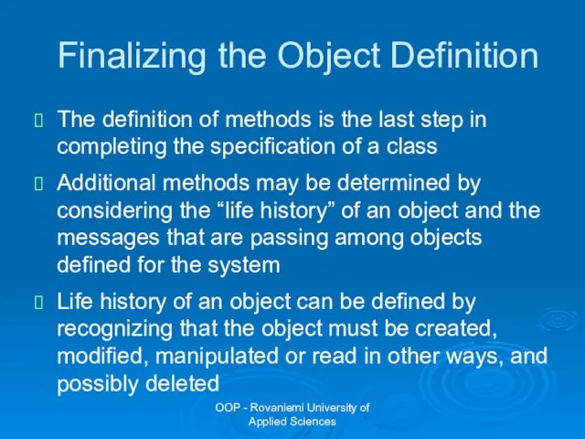
Finalizing the Object Definition
The definition of
OOP - Rovaniemi University of Applied Sciences
Finalizing the Object Definition
The definition of
Слайд 52OOP - Rovaniemi University of Applied Sciences
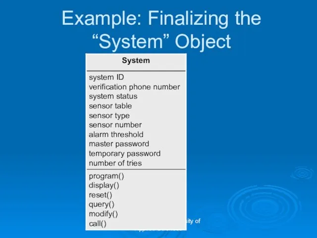
Example: Finalizing the “System” Object
program()
display()
reset()
query()
modify()
call()
system ID
verification
OOP - Rovaniemi University of Applied Sciences
Example: Finalizing the “System” Object
program()
display()
reset()
query()
modify()
call()
system ID
verification
Слайд 53OOP - Rovaniemi University of Applied Sciences
Group Work
Define attributes and methods for
OOP - Rovaniemi University of Applied Sciences
Group Work
Define attributes and methods for

Слайд 54OOP - Rovaniemi University of Applied Sciences
Tasks for Object-Oriented Analysis
Basic user requirements
OOP - Rovaniemi University of Applied Sciences
Tasks for Object-Oriented Analysis
Basic user requirements

Слайд 55OOP - Rovaniemi University of Applied Sciences
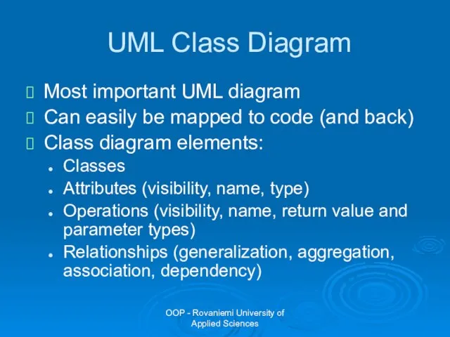
UML Class Diagram
Most important UML diagram
Can
OOP - Rovaniemi University of Applied Sciences
UML Class Diagram
Most important UML diagram
Can
Слайд 56OOP - Rovaniemi University of Applied Sciences
Example of a Class in an
OOP - Rovaniemi University of Applied Sciences
Example of a Class in an

Слайд 57OOP - Rovaniemi University of Applied Sciences
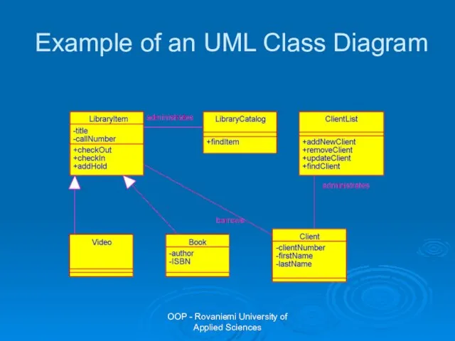
Example of an UML Class Diagram
OOP - Rovaniemi University of Applied Sciences
Example of an UML Class Diagram
Слайд 58OOP - Rovaniemi University of Applied Sciences
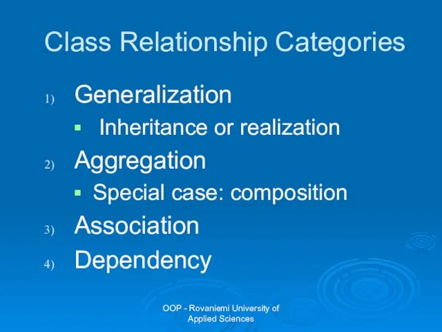
Class Relationship Categories
Generalization
Inheritance or realization
Aggregation
Special
OOP - Rovaniemi University of Applied Sciences
Class Relationship Categories
Generalization
Inheritance or realization
Aggregation
Special
Слайд 59OOP - Rovaniemi University of Applied Sciences
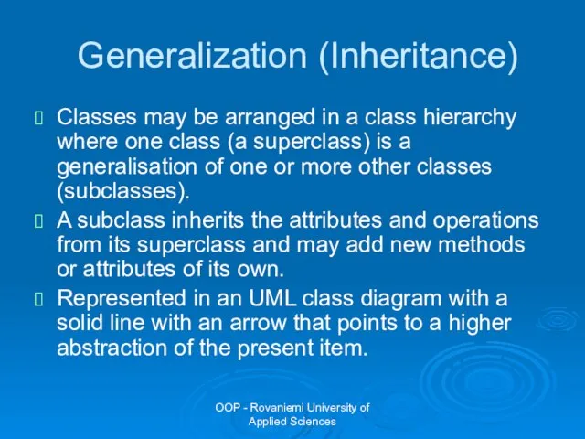
Generalization (Inheritance)
Classes may be arranged in
OOP - Rovaniemi University of Applied Sciences
Generalization (Inheritance)
Classes may be arranged in
Слайд 60OOP - Rovaniemi University of Applied Sciences
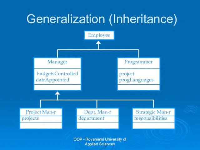
Generalization (Inheritance)
OOP - Rovaniemi University of Applied Sciences
Generalization (Inheritance)
Слайд 61OOP - Rovaniemi University of Applied Sciences
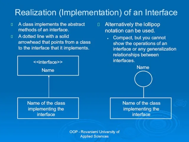
Realization (Implementation) of an Interface
A class
OOP - Rovaniemi University of Applied Sciences
Realization (Implementation) of an Interface
A class
Слайд 62OOP - Rovaniemi University of Applied Sciences
Aggregation
Shows how classes that are collections
OOP - Rovaniemi University of Applied Sciences
Aggregation
Shows how classes that are collections
Слайд 63OOP - Rovaniemi University of Applied Sciences
Composition
Composition is a special form of
OOP - Rovaniemi University of Applied Sciences
Composition
Composition is a special form of
Слайд 64OOP - Rovaniemi University of Applied Sciences
Composition vs. Aggregation
Composition is a stricter
OOP - Rovaniemi University of Applied Sciences
Composition vs. Aggregation
Composition is a stricter
Слайд 65OOP - Rovaniemi University of Applied Sciences
Association
A solid line that represents that
OOP - Rovaniemi University of Applied Sciences
Association
A solid line that represents that
Слайд 66OOP - Rovaniemi University of Applied Sciences
Attributes and Associations
Attributes and associations are
OOP - Rovaniemi University of Applied Sciences
Attributes and Associations
Attributes and associations are

Слайд 67OOP - Rovaniemi University of Applied Sciences
Dependency
A dotted line with an open
OOP - Rovaniemi University of Applied Sciences
Dependency
A dotted line with an open

Слайд 68OOP - Rovaniemi University of Applied Sciences
Qualified Association
University
Student
-
name: string
-
address: string
studentID:int
1
0..1
University
Student
-
OOP - Rovaniemi University of Applied Sciences
Qualified Association
University
Student
-
name: string
-
address: string
studentID:int
1
0..1
University
Student
-

Слайд 69OOP - Rovaniemi University of Applied Sciences
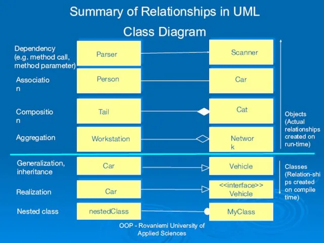
Association
Aggregation
Composition
Person
owns
Car
Workstation
Cat
Tail
Network
Generalization,
inheritance
Car
Vehicle
Realization
<>
Vehicle
Car
Dependency
(e.g. method call,
method parameter)
Parser
Scanner
Summary of
OOP - Rovaniemi University of Applied Sciences
Association
Aggregation
Composition
Person
owns
Car
Workstation
Cat
Tail
Network
Generalization,
inheritance
Car
Vehicle
Realization
< Car Dependency Parser Scanner Summary of
Vehicle
(e.g. method call,
method parameter)
Слайд 70OOP - Rovaniemi University of Applied Sciences
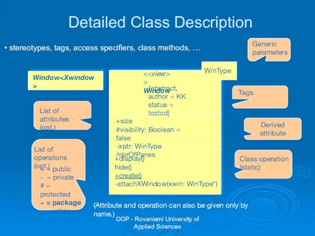
<>
Window
{abstract,
author = KK
status = tested}
+size
#visibility: Boolean
OOP - Rovaniemi University of Applied Sciences
< {abstract, +size
Window
author = KK
status = tested}
#visibility: Boolean
Слайд 71OOP - Rovaniemi University of Applied Sciences
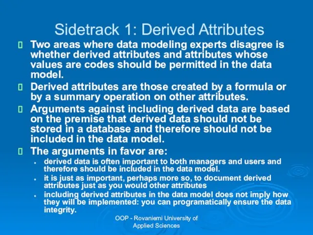
Sidetrack 1: Derived Attributes
Two areas where
OOP - Rovaniemi University of Applied Sciences
Sidetrack 1: Derived Attributes
Two areas where
Слайд 72OOP - Rovaniemi University of Applied Sciences
Sidetrack 2: Code Values
A coded value
OOP - Rovaniemi University of Applied Sciences
Sidetrack 2: Code Values
A coded value
Слайд 73OOP - Rovaniemi University of Applied Sciences
Group Work
Draw an UML class diagram
OOP - Rovaniemi University of Applied Sciences
Group Work
Draw an UML class diagram
Слайд 74OOP - Rovaniemi University of Applied Sciences
Tasks for Object-Oriented Analysis
Basic user requirements
OOP - Rovaniemi University of Applied Sciences
Tasks for Object-Oriented Analysis
Basic user requirements
Слайд 75OOP - Rovaniemi University of Applied Sciences
Steps for Creating a Behavioral Model
Behavioral
OOP - Rovaniemi University of Applied Sciences
Steps for Creating a Behavioral Model
Behavioral
Слайд 76OOP - Rovaniemi University of Applied Sciences
Creating a Behavioral Model
Examine the use
OOP - Rovaniemi University of Applied Sciences
Creating a Behavioral Model
Examine the use
Слайд 77OOP - Rovaniemi University of Applied Sciences
Creating a Behavioral Model
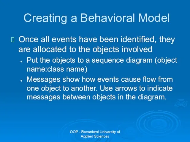
Once all events
OOP - Rovaniemi University of Applied Sciences
Creating a Behavioral Model
Once all events
Слайд 78OOP - Rovaniemi University of Applied Sciences
SET
ALARM
M
H
:Ringer
Switch on
:Light
Press ALARM
Show time
:User
:Control
Start alarm
Press
OOP - Rovaniemi University of Applied Sciences
SET
ALARM
M
H
:Ringer
Switch on
:Light
Press ALARM
Show time
:User
:Control
Start alarm
Press

Слайд 79OOP - Rovaniemi University of Applied Sciences
Sequence Diagram Notation
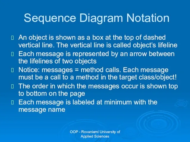
An object is shown
OOP - Rovaniemi University of Applied Sciences
Sequence Diagram Notation
An object is shown
Слайд 80OOP - Rovaniemi University of Applied Sciences
Sequence Diagram Notation
You can show a
OOP - Rovaniemi University of Applied Sciences
Sequence Diagram Notation
You can show a

Слайд 81OOP - Rovaniemi University of Applied Sciences
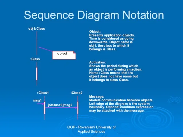
Sequence Diagram Notation
OOP - Rovaniemi University of Applied Sciences
Sequence Diagram Notation
Слайд 82OOP - Rovaniemi University of Applied Sciences
Asyncronous Messages in Sequence Diagram
The half-arrowheads
OOP - Rovaniemi University of Applied Sciences
Asyncronous Messages in Sequence Diagram
The half-arrowheads

Слайд 83OOP - Rovaniemi University of Applied Sciences
Object Creation and Deletion in Sequence
OOP - Rovaniemi University of Applied Sciences
Object Creation and Deletion in Sequence

Слайд 84OOP - Rovaniemi University of Applied Sciences
Group Work
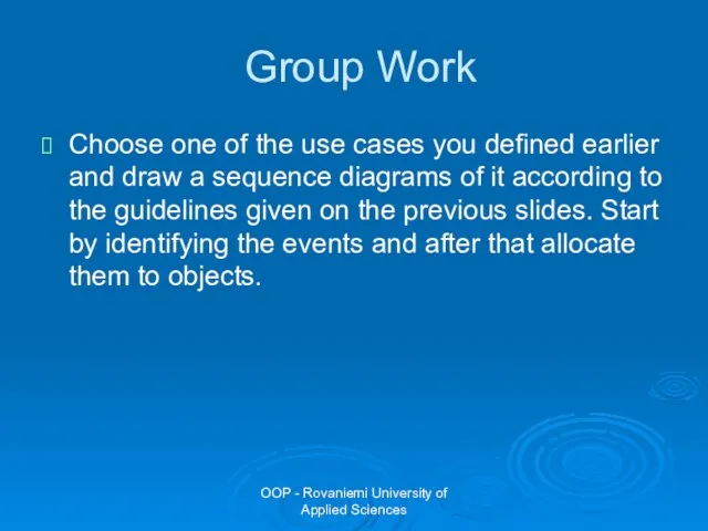
Choose one of the use
OOP - Rovaniemi University of Applied Sciences
Group Work
Choose one of the use
Слайд 85OOP - Rovaniemi University of Applied Sciences
SET
pressed
Do: showTime
Ready
M/add minutes
H/add hours
SET
pressed
[time
OOP - Rovaniemi University of Applied Sciences
SET
pressed
Do: showTime
Ready
M/add minutes
H/add hours
SET
pressed
[time
Слайд 86OOP - Rovaniemi University of Applied Sciences
State Diagram Notation
State diagram represents active
OOP - Rovaniemi University of Applied Sciences
State Diagram Notation
State diagram represents active
Слайд 87OOP - Rovaniemi University of Applied Sciences
State Diagram Notation: Actions
Entry: action
Action is
OOP - Rovaniemi University of Applied Sciences
State Diagram Notation: Actions
Entry: action
Action is
Слайд 88OOP - Rovaniemi University of Applied Sciences
Summary
Sequence diagram shows typical interactions between
OOP - Rovaniemi University of Applied Sciences
Summary
Sequence diagram shows typical interactions between

Слайд 89OOP - Rovaniemi University of Applied Sciences
Group Work
Choose one of the classes
OOP - Rovaniemi University of Applied Sciences
Group Work
Choose one of the classes
 Презентация на тему: Инфляция и семейная экономика
 Thematic studio workshop. Requirements professors
 Презентация на тему Направления современной живописи
 Собери урожай
 Силы всемирного тяготения
 Российское сельскохозяйственное тракторостроение: Как нам победить John Deere?
 ШCК Заброденец. Дополнительно образование в школе
 Market economy and pubic policy
 Задачи учет затрат в производстве
 ВКР: Анализ эффективности деятельности таможенных органов РФ по формированию доходов Федерального бюджета
 Творческое наследие М. Ю. Лермонтова
 Презентация группы «Словесники»
 Выпускная письменная работа: Техническое обслуживание и ремонт грузоподъемных механизмов
 ПЛАН РАБОТЫ ШКОЛЫ В НОВОГОДНИЕ КАНИКУЛЫ
 Развод и последующий за ним раздел имущества
 Тема «Бюджет»
 Творчество в СССР
 Гидротехника и гидроэнергетика России. Состояние и перспективы 2021 (1)
 Бункерно-загрузочные устройства
 Презентация на тему Технология токарных работ по дереву
 Ткани. Типы тканей и их свойства
 Введение в профессию стилист
 Понятия войны и мира: соотношение понятий. Типология военных конфликтов. Война и международная безопасность: причины войн
 Uchebnaya_praktika_Golub_Maria_20PI-2
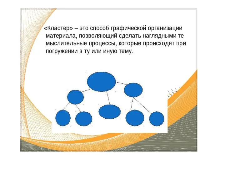 Кластер
 Солнечная индустриальная компания
 Графика в костюме
 Обследование и реконструкция сетей и сооружений систем водного хозяйства (Лекция 3)