- A Drill Pipe Management

Содержание
- 2. Why Do You Need A Drill Pipe Management Program? Drill Pipe Is Your Single Largest Investment
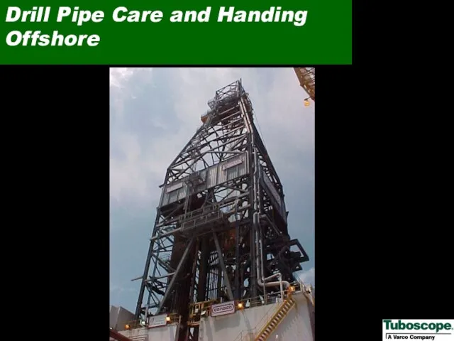
- 3. Drill Pipe Care and Handing Offshore
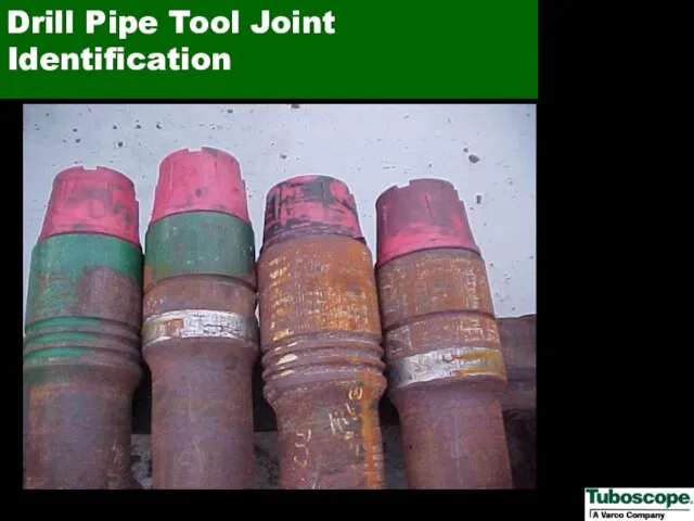
- 4. Drill Pipe Tool Joint Identification
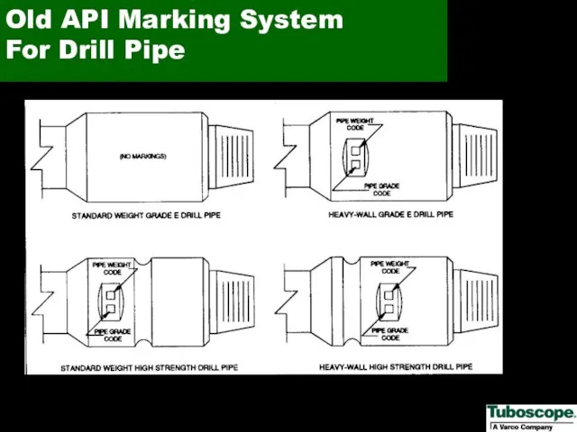
- 5. Old API Marking System For Drill Pipe
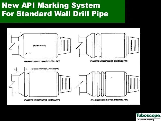
- 6. New API Marking System For Standard Wall Drill Pipe
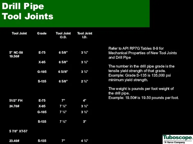
- 7. Refer to API RP7G Tables 8-9 for Mechanical Properties of New Tool Joints and Drill Pipe
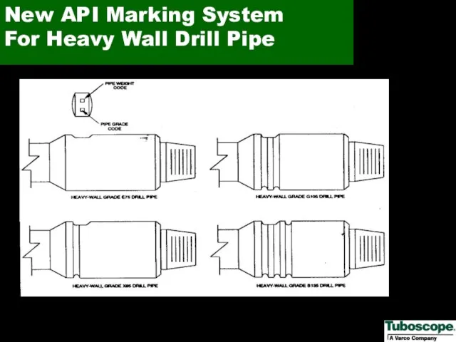
- 8. New API Marking System For Heavy Wall Drill Pipe
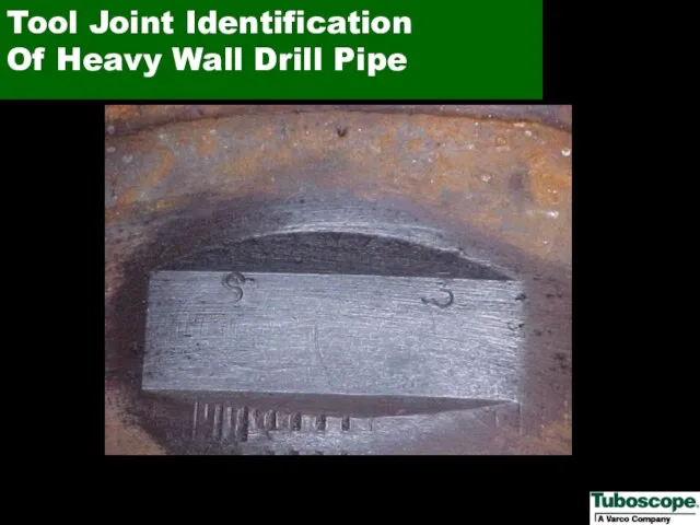
- 9. Tool Joint Identification Of Heavy Wall Drill Pipe
- 10. Weight and Grade Codes
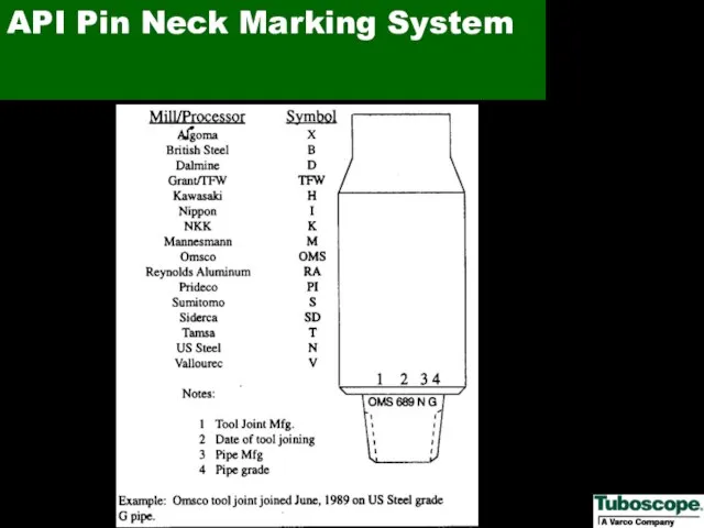
- 11. API Pin Neck Marking System
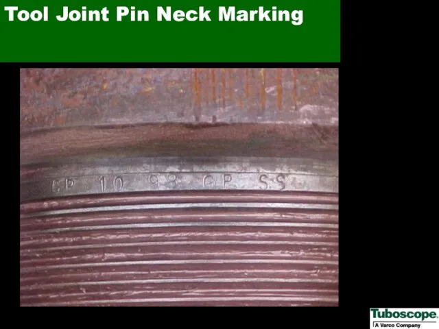
- 12. Tool Joint Pin Neck Marking
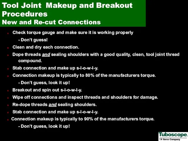
- 13. Check torque gauge and make sure it is working properly - Don’t guess! Clean and dry
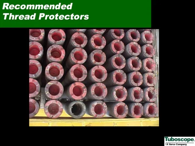
- 14. Recommended Thread Protectors
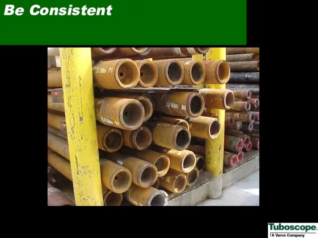
- 15. Be Consistent
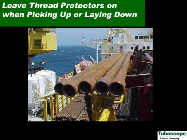
- 16. Leave Thread Protectors on when Picking Up or Laying Down
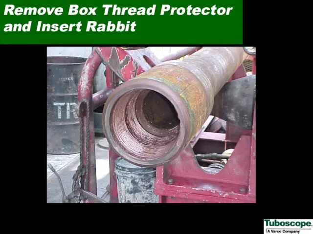
- 17. Remove Box Thread Protector and Insert Rabbit
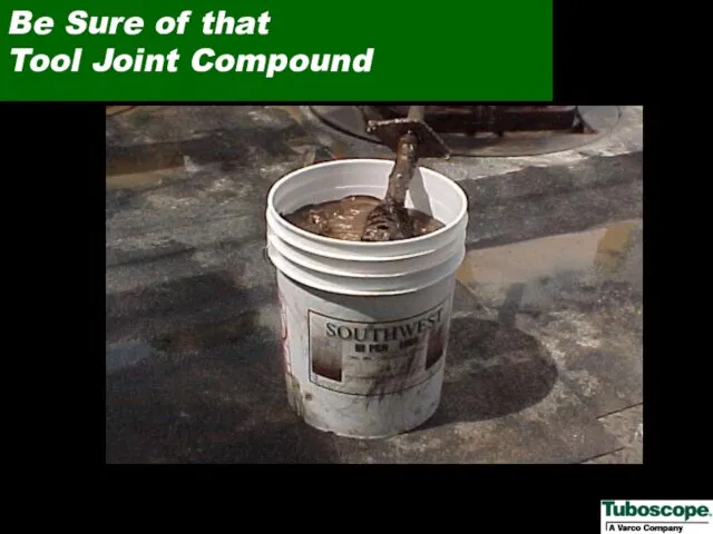
- 18. Be Sure of that Tool Joint Compound
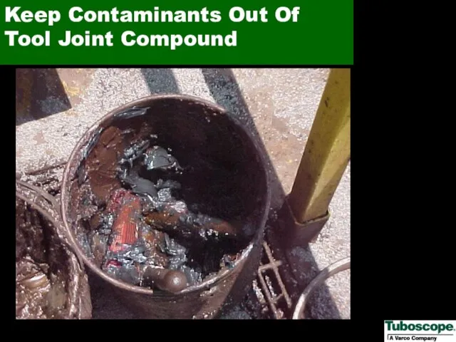
- 19. Keep Contaminants Out Of Tool Joint Compound
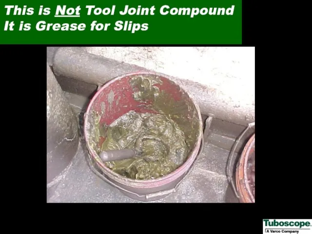
- 20. This is Not Tool Joint Compound It is Grease for Slips
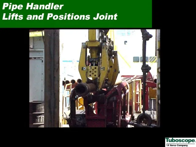
- 21. Pipe Handler Lifts and Positions Joint
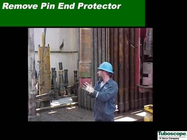
- 22. Remove Pin End Protector
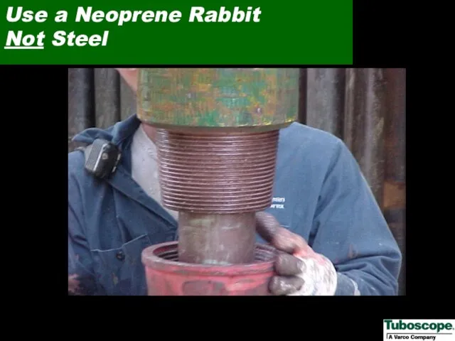
- 23. Use a Neoprene Rabbit Not Steel
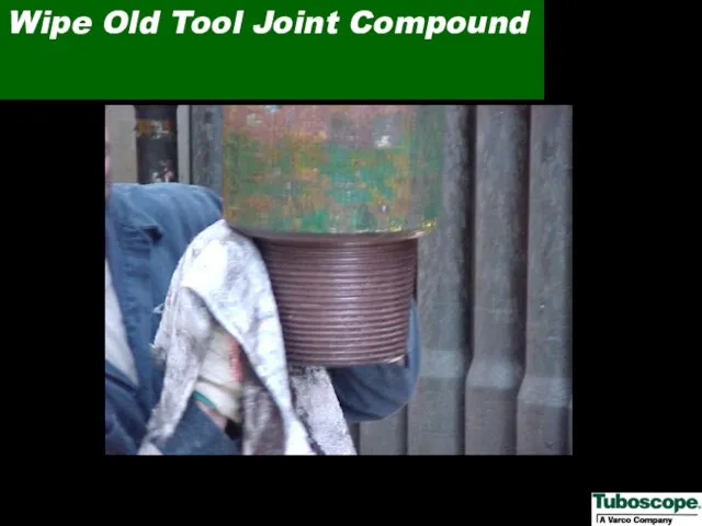
- 24. Wipe Old Tool Joint Compound
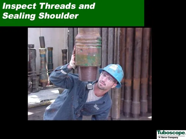
- 25. Inspect Threads and Sealing Shoulder
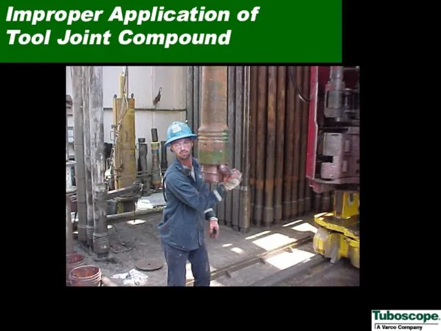
- 26. Improper Application of Tool Joint Compound
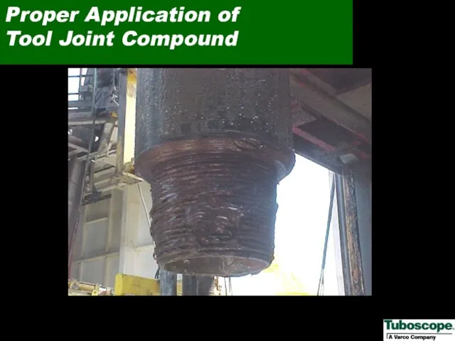
- 27. Proper Application of Tool Joint Compound
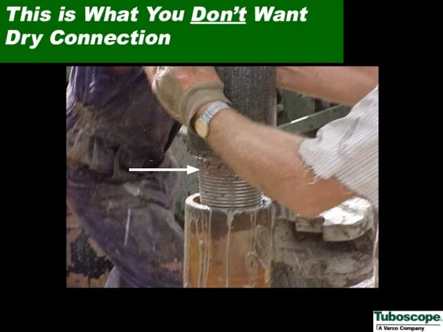
- 28. This is What You Don’t Want Dry Connection
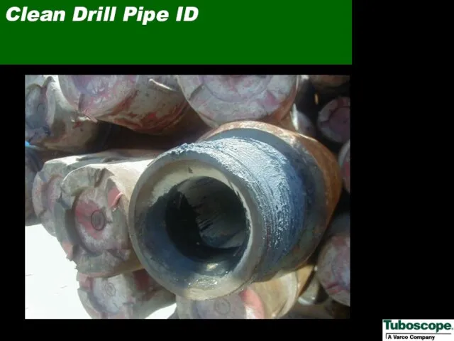
- 29. Clean Drill Pipe ID
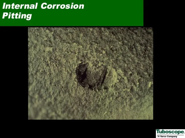
- 30. Internal Corrosion Pitting
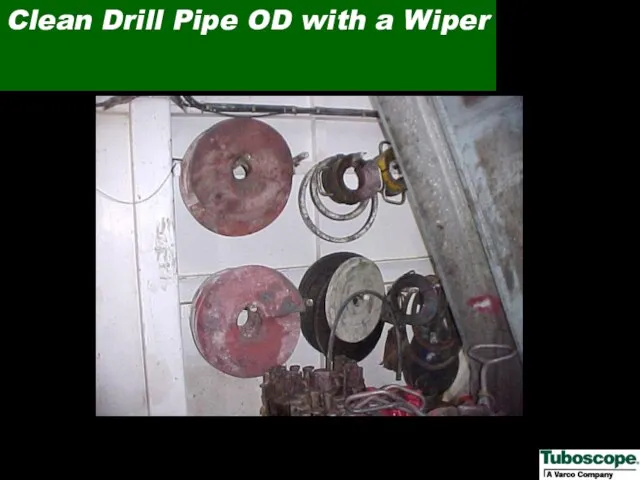
- 31. Clean Drill Pipe OD with a Wiper
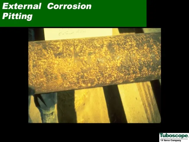
- 32. External Corrosion Pitting
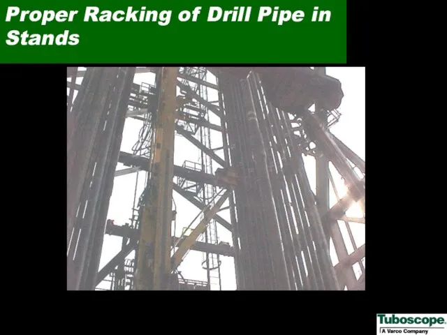
- 33. Proper Racking of Drill Pipe in Stands
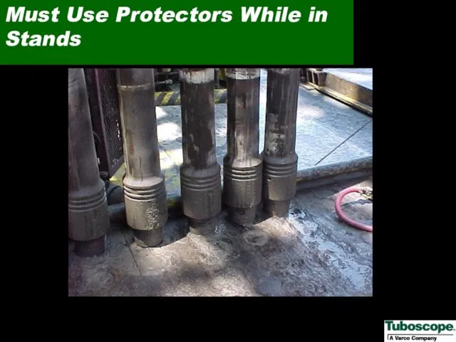
- 34. Must Use Protectors While in Stands
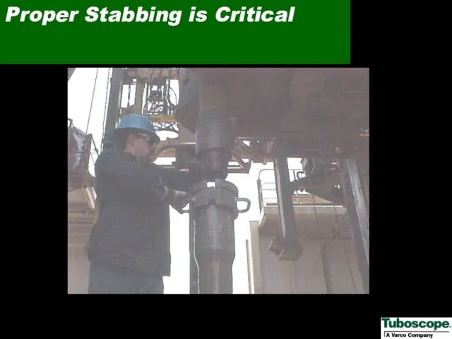
- 35. Proper Stabbing is Critical
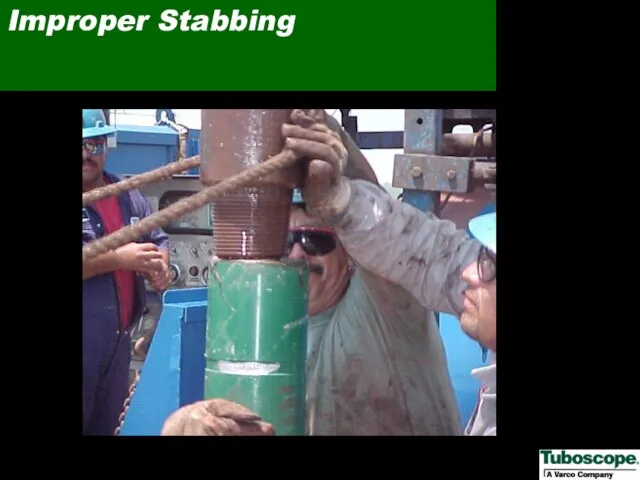
- 36. Improper Stabbing
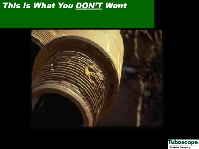
- 37. This Is What You DON’T Want
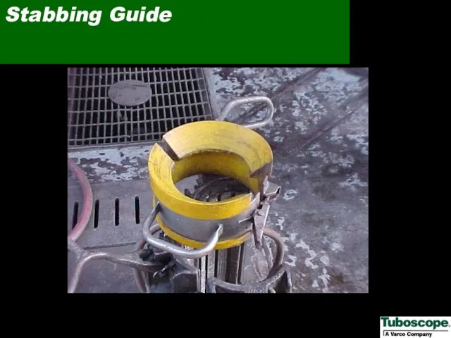
- 38. Stabbing Guide
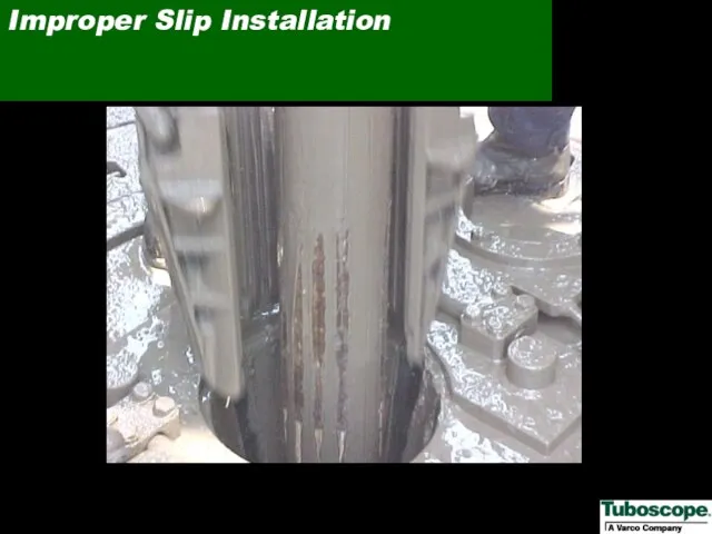
- 39. Improper Slip Installation
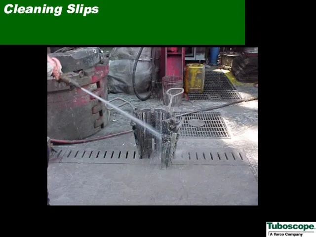
- 40. Cleaning Slips
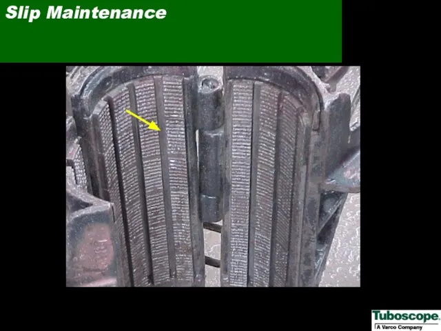
- 41. Slip Maintenance
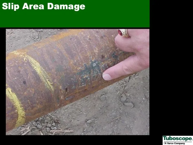
- 42. Slip Area Damage
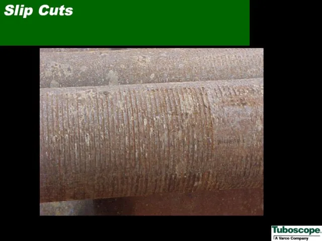
- 43. Slip Cuts
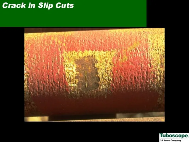
- 44. Crack in Slip Cuts
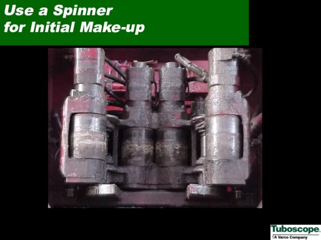
- 45. Use a Spinner for Initial Make-up
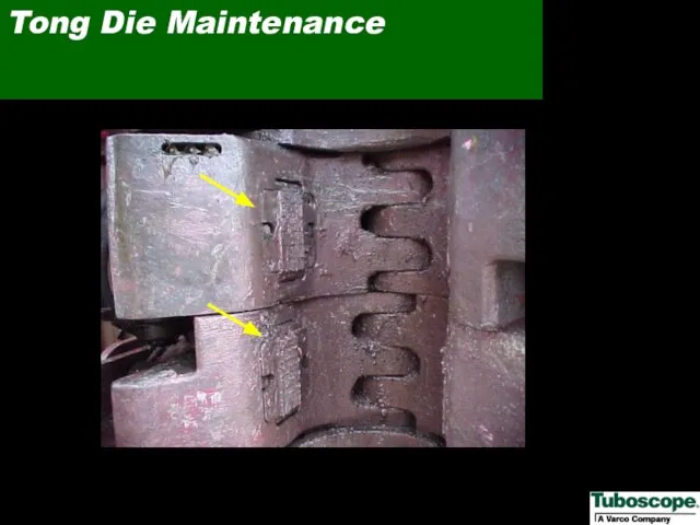
- 46. Tong Die Maintenance
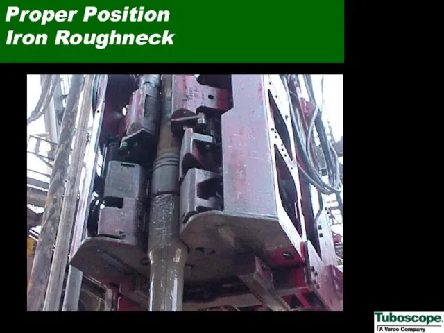
- 47. Proper Position Iron Roughneck
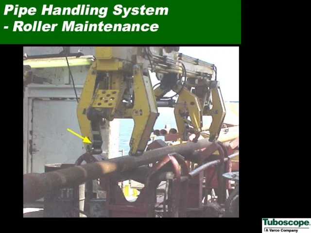
- 48. Pipe Handling System - Roller Maintenance
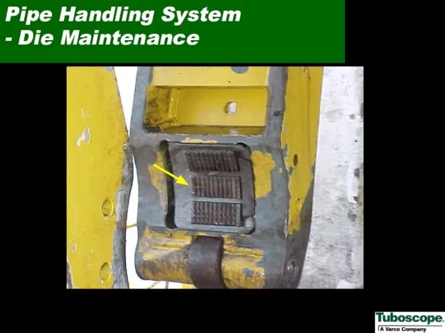
- 49. Pipe Handling System - Die Maintenance
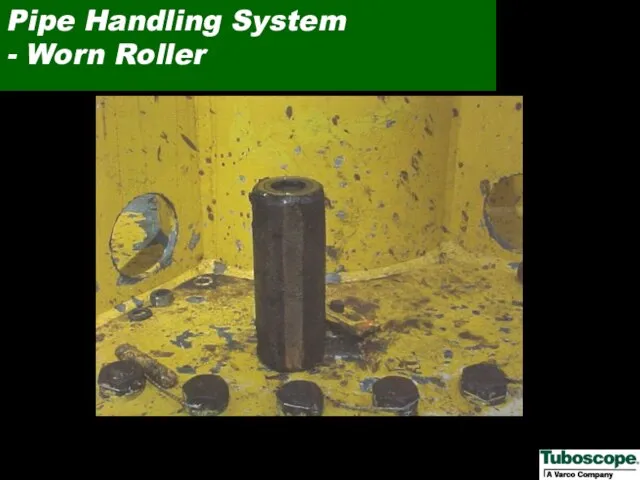
- 50. Pipe Handling System - Worn Roller
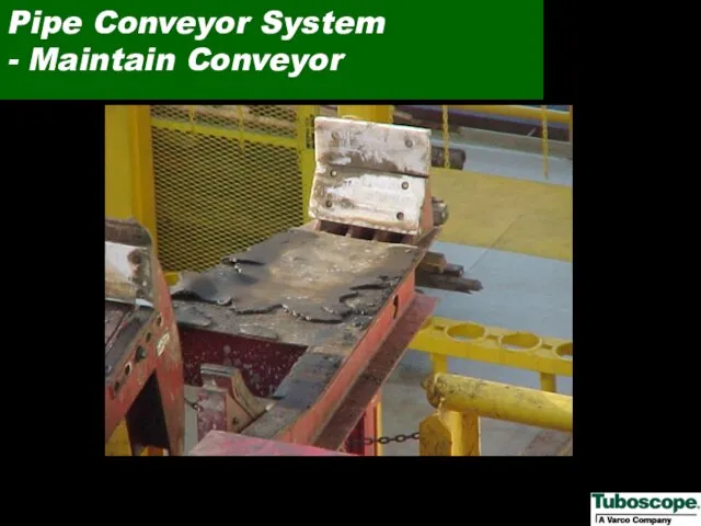
- 51. Pipe Conveyor System - Maintain Conveyor
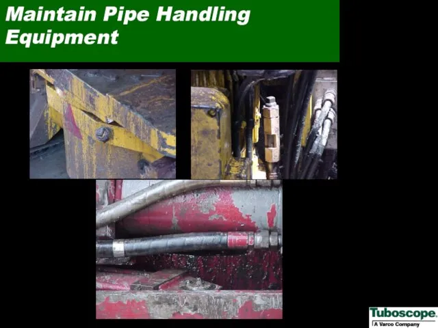
- 52. Maintain Pipe Handling Equipment
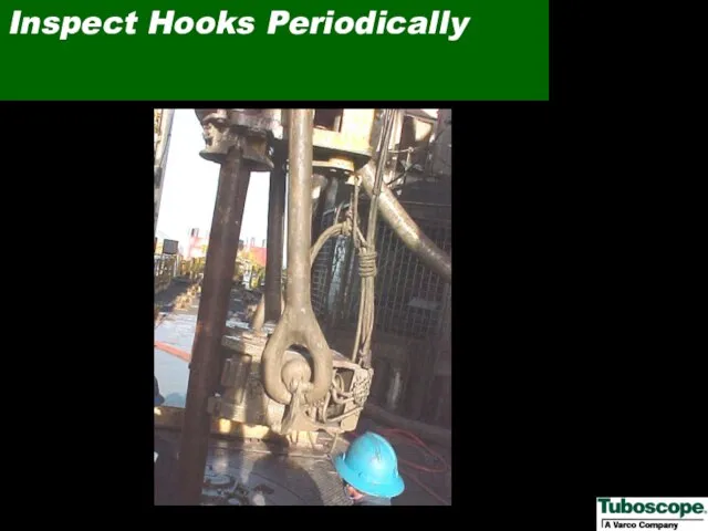
- 53. Inspect Hooks Periodically
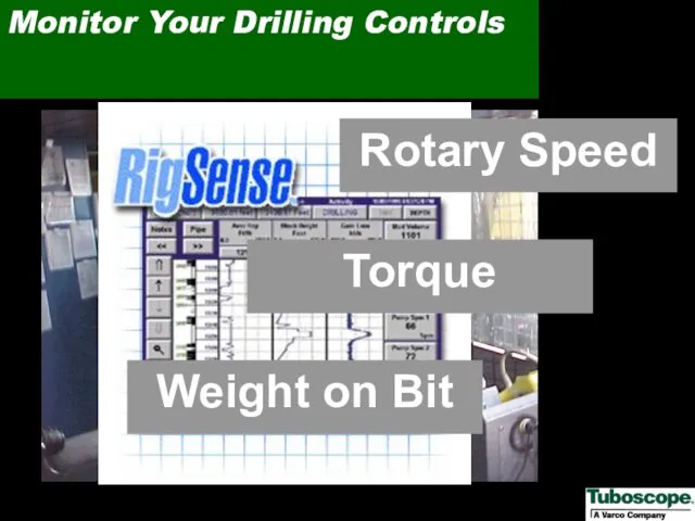
- 54. Monitor Your Drilling Controls Rotary Speed Torque Weight on Bit
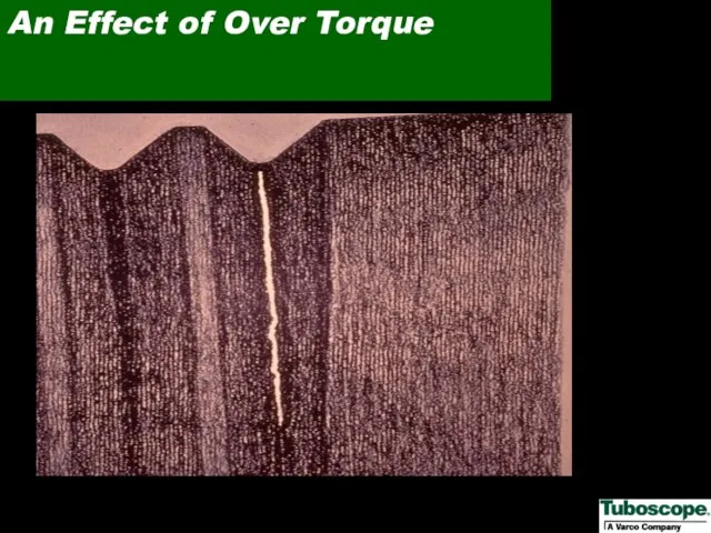
- 55. An Effect of Over Torque
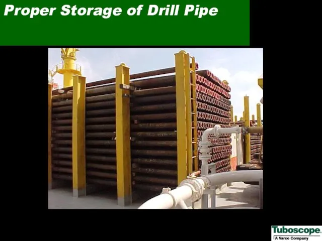
- 56. Proper Storage of Drill Pipe
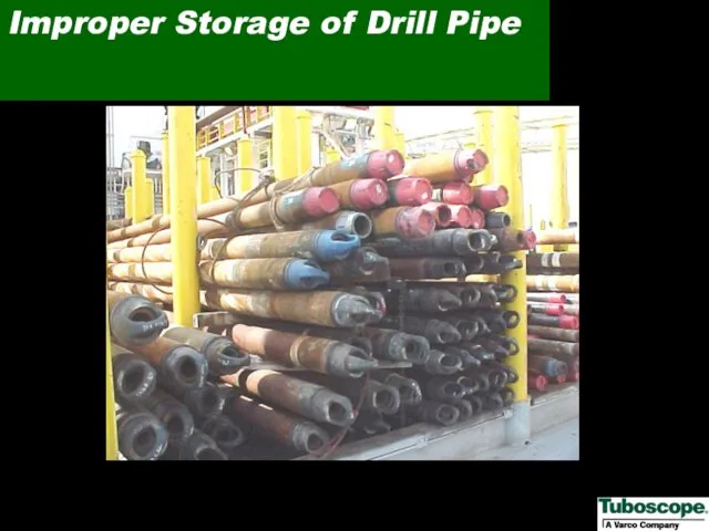
- 57. Improper Storage of Drill Pipe
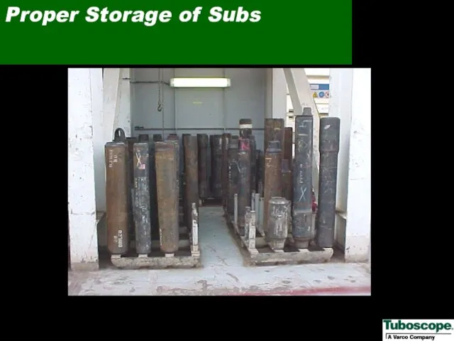
- 58. Proper Storage of Subs
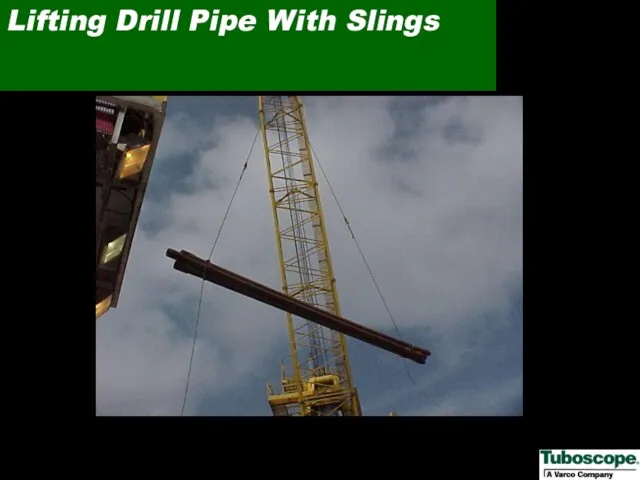
- 59. Lifting Drill Pipe With Slings
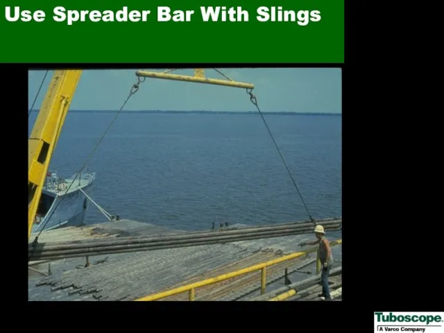
- 60. Use Spreader Bar With Slings
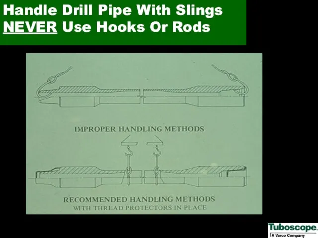
- 61. Handle Drill Pipe With Slings NEVER Use Hooks Or Rods
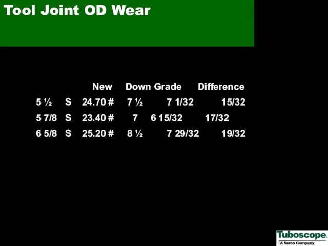
- 62. Tool Joint OD Wear New Down Grade Difference 5 ½ S 24.70 # 7 ½ 7
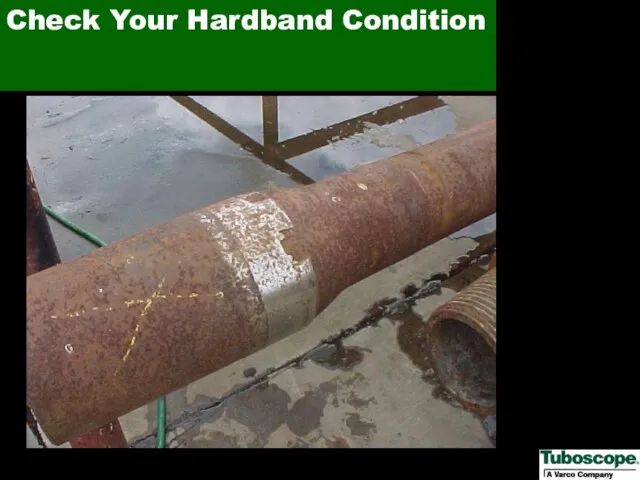
- 63. Check Your Hardband Condition
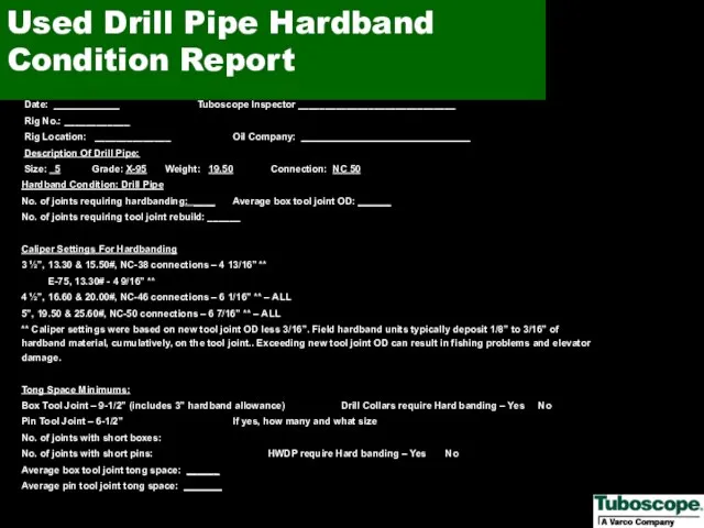
- 64. Date: ____________ Tuboscope Inspector _____________________________ Rig No.: ____________ Rig Location: ______________ Oil Company: _______________________________ Description Of
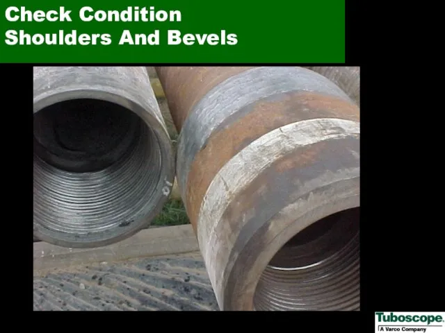
- 65. Check Condition Shoulders And Bevels
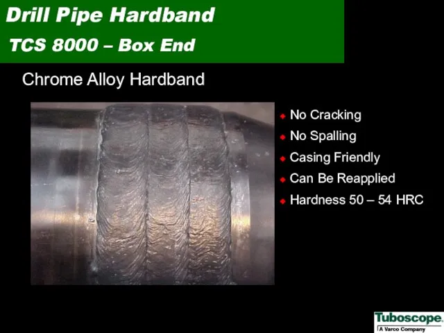
- 66. Chrome Alloy Hardband Drill Pipe Hardband TCS 8000 – Box End No Cracking No Spalling Casing
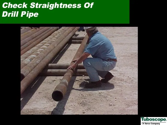
- 67. Check Straightness Of Drill Pipe
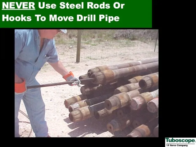
- 68. NEVER Use Steel Rods Or Hooks To Move Drill Pipe
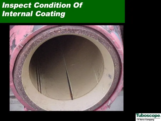
- 69. Inspect Condition Of Internal Coating
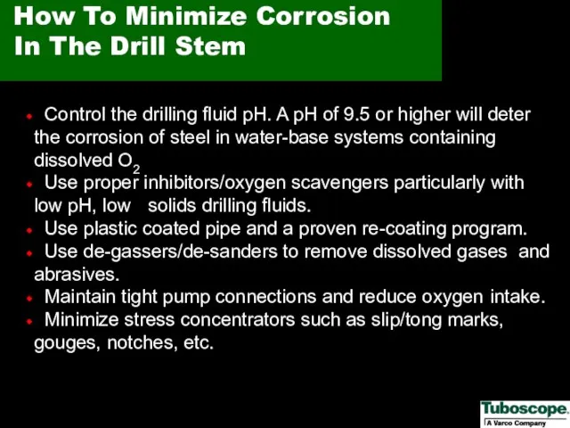
- 70. How To Minimize Corrosion In The Drill Stem Control the drilling fluid pH. A pH of
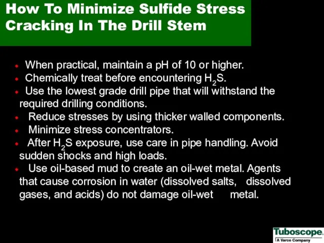
- 71. How To Minimize Sulfide Stress Cracking In The Drill Stem When practical, maintain a pH of
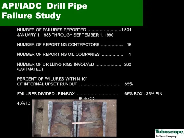
- 72. API/IADC Drill Pipe Failure Study NUMBER OF FAILURES REPORTED …………………….1,801 JANUARY 1, 1988 THROUGH SEPTEMBER 1,
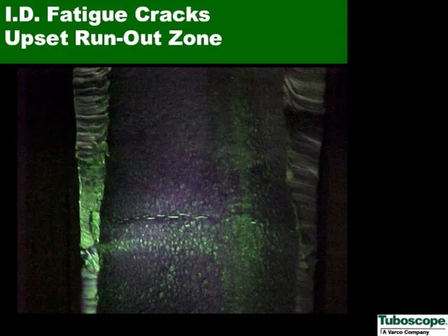
- 73. I.D. Fatigue Cracks Upset Run-Out Zone
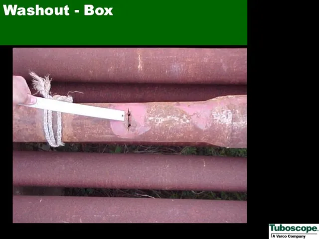
- 74. Washout - Box
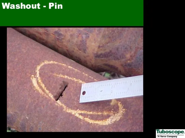
- 75. Washout - Pin
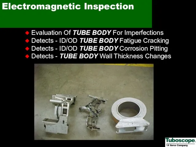
- 76. Electromagnetic Inspection Evaluation Of TUBE BODY For Imperfections Detects - ID/OD TUBE BODY Fatigue Cracking Detects
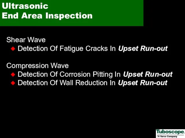
- 77. Ultrasonic End Area Inspection Shear Wave Detection Of Fatigue Cracks In Upset Run-out Compression Wave Detection
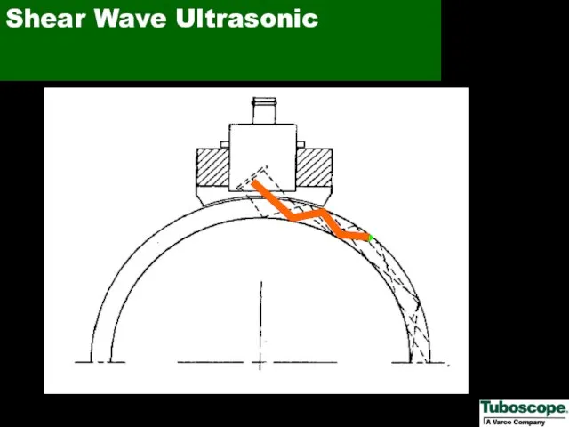
- 78. Shear Wave Ultrasonic
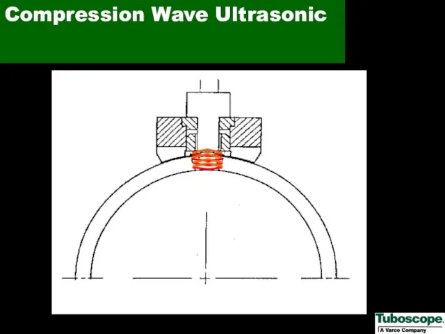
- 79. Compression Wave Ultrasonic
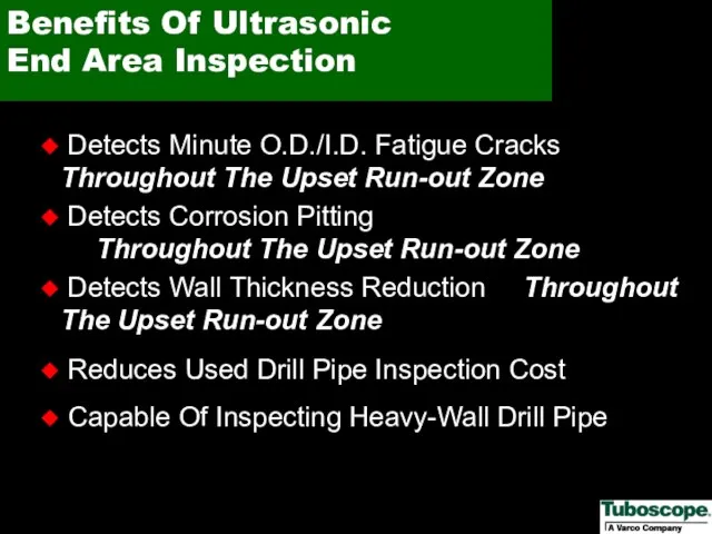
- 80. Benefits Of Ultrasonic End Area Inspection Detects Minute O.D./I.D. Fatigue Cracks Throughout The Upset Run-out Zone
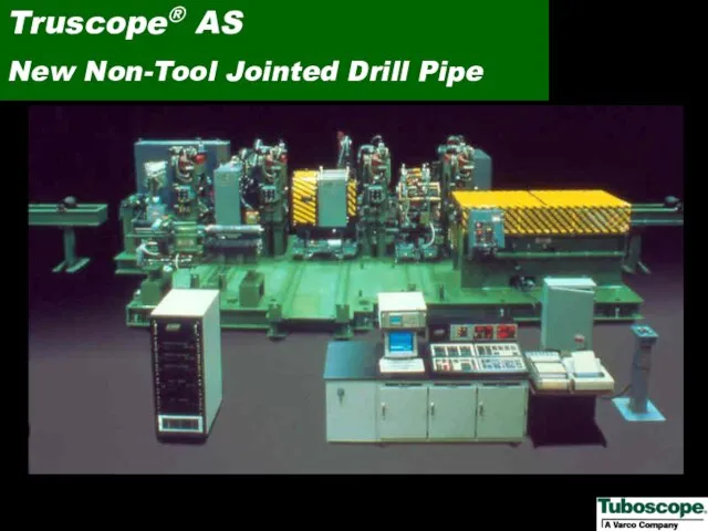
- 81. Truscope® AS New Non-Tool Jointed Drill Pipe
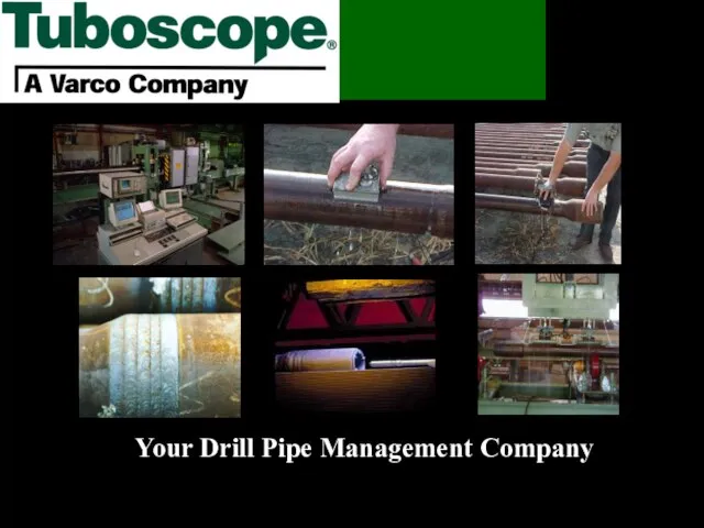
- 82. Your Drill Pipe Management Company
- 83. Tuboscope would like to express special thanks to both Conoco Inc. and Transocean Offshore Deepwater Drilling
- 85. Скачать презентацию
Слайд 3Drill Pipe Care and Handing
Offshore
Drill Pipe Care and Handing
Offshore
Слайд 4Drill Pipe Tool Joint
Identification
Drill Pipe Tool Joint
Identification
Слайд 5Old API Marking System
For Drill Pipe
Old API Marking System
For Drill Pipe
Слайд 6New API Marking System
For Standard Wall Drill Pipe
New API Marking System
For Standard Wall Drill Pipe
Слайд 7Refer to API RP7G Tables 8-9 for Mechanical Properties of New Tool
Refer to API RP7G Tables 8-9 for Mechanical Properties of New Tool
Слайд 8New API Marking System
For Heavy Wall Drill Pipe
New API Marking System
For Heavy Wall Drill Pipe
Слайд 9Tool Joint Identification
Of Heavy Wall Drill Pipe
Tool Joint Identification
Of Heavy Wall Drill Pipe
Слайд 10Weight and Grade Codes
Weight and Grade Codes

Слайд 11API Pin Neck Marking System
API Pin Neck Marking System
Слайд 12Tool Joint Pin Neck Marking
Tool Joint Pin Neck Marking
Слайд 13 Check torque gauge and make sure it is working properly
-
Check torque gauge and make sure it is working properly
-
Слайд 14Recommended
Thread Protectors
Recommended
Thread Protectors
Слайд 15Be Consistent
Be Consistent
Слайд 16Leave Thread Protectors on when Picking Up or Laying Down
Leave Thread Protectors on when Picking Up or Laying Down
Слайд 17Remove Box Thread Protector and Insert Rabbit
Remove Box Thread Protector and Insert Rabbit
Слайд 18Be Sure of that
Tool Joint Compound
Be Sure of that
Tool Joint Compound
Слайд 19Keep Contaminants Out Of Tool Joint Compound
Keep Contaminants Out Of Tool Joint Compound
Слайд 20This is Not Tool Joint Compound
It is Grease for Slips
This is Not Tool Joint Compound
It is Grease for Slips
Слайд 21Pipe Handler
Lifts and Positions Joint
Pipe Handler
Lifts and Positions Joint
Слайд 22Remove Pin End Protector
Remove Pin End Protector
Слайд 23Use a Neoprene Rabbit
Not Steel
Use a Neoprene Rabbit
Not Steel
Слайд 24Wipe Old Tool Joint Compound
Wipe Old Tool Joint Compound
Слайд 25Inspect Threads and
Sealing Shoulder
Inspect Threads and
Sealing Shoulder
Слайд 26Improper Application of
Tool Joint Compound
Improper Application of
Tool Joint Compound
Слайд 27Proper Application of
Tool Joint Compound
Proper Application of
Tool Joint Compound
Слайд 28This is What You Don’t Want
Dry Connection
This is What You Don’t Want
Dry Connection
Слайд 29Clean Drill Pipe ID
Clean Drill Pipe ID
Слайд 30Internal Corrosion
Pitting
Internal Corrosion
Pitting
Слайд 31Clean Drill Pipe OD with a Wiper
Clean Drill Pipe OD with a Wiper
Слайд 32External Corrosion
Pitting
External Corrosion
Pitting
Слайд 33Proper Racking of Drill Pipe in Stands
Proper Racking of Drill Pipe in Stands
Слайд 34Must Use Protectors While in Stands
Must Use Protectors While in Stands
Слайд 35Proper Stabbing is Critical
Proper Stabbing is Critical
Слайд 36Improper Stabbing
Improper Stabbing
Слайд 37This Is What You DON’T Want
This Is What You DON’T Want
Слайд 38Stabbing Guide
Stabbing Guide
Слайд 39Improper Slip Installation
Improper Slip Installation
Слайд 40Cleaning Slips
Cleaning Slips
Слайд 41Slip Maintenance
Slip Maintenance
Слайд 42Slip Area Damage
Slip Area Damage
Слайд 43Slip Cuts
Slip Cuts
Слайд 44Crack in Slip Cuts
Crack in Slip Cuts
Слайд 45Use a Spinner
for Initial Make-up
Use a Spinner
for Initial Make-up
Слайд 46Tong Die Maintenance
Tong Die Maintenance
Слайд 47Proper Position
Iron Roughneck
Proper Position
Iron Roughneck
Слайд 48Pipe Handling System
- Roller Maintenance
Pipe Handling System
- Roller Maintenance
Слайд 49Pipe Handling System
- Die Maintenance
Pipe Handling System
- Die Maintenance
Слайд 50Pipe Handling System
- Worn Roller
Pipe Handling System
- Worn Roller
Слайд 51Pipe Conveyor System
- Maintain Conveyor
Pipe Conveyor System
- Maintain Conveyor
Слайд 52Maintain Pipe Handling
Equipment
Maintain Pipe Handling
Equipment
Слайд 53Inspect Hooks Periodically
Inspect Hooks Periodically
Слайд 54Monitor Your Drilling Controls
Rotary Speed
Torque
Weight on Bit
Monitor Your Drilling Controls
Rotary Speed
Torque
Weight on Bit
Слайд 55An Effect of Over Torque
An Effect of Over Torque
Слайд 56Proper Storage of Drill Pipe
Proper Storage of Drill Pipe
Слайд 57Improper Storage of Drill Pipe
Improper Storage of Drill Pipe
Слайд 58Proper Storage of Subs
Proper Storage of Subs
Слайд 59Lifting Drill Pipe With Slings
Lifting Drill Pipe With Slings
Слайд 60Use Spreader Bar With Slings
Use Spreader Bar With Slings
Слайд 61Handle Drill Pipe With Slings
NEVER Use Hooks Or Rods
Handle Drill Pipe With Slings
NEVER Use Hooks Or Rods
Слайд 62Tool Joint OD Wear
New Down Grade Difference
5 ½ S 24.70 #
Tool Joint OD Wear
New Down Grade Difference
5 ½ S 24.70 #
Слайд 63Check Your Hardband Condition
Check Your Hardband Condition
Слайд 64 Date: ____________ Tuboscope Inspector _____________________________
Rig No.: ____________
Rig Location: ______________ Oil Company: _______________________________
Description
Date: ____________ Tuboscope Inspector _____________________________
Rig No.: ____________
Rig Location: ______________ Oil Company: _______________________________
Description
Слайд 65Check Condition
Shoulders And Bevels
Check Condition
Shoulders And Bevels
Слайд 66Chrome Alloy Hardband
Drill Pipe Hardband
TCS 8000 – Box End
No Cracking
Chrome Alloy Hardband
Drill Pipe Hardband
TCS 8000 – Box End
No Cracking
Слайд 67Check Straightness Of
Drill Pipe
Check Straightness Of
Drill Pipe
Слайд 68NEVER Use Steel Rods Or Hooks To Move Drill Pipe
NEVER Use Steel Rods Or Hooks To Move Drill Pipe
Слайд 69Inspect Condition Of
Internal Coating
Inspect Condition Of
Internal Coating
Слайд 70How To Minimize Corrosion
In The Drill Stem
Control the drilling fluid
How To Minimize Corrosion
In The Drill Stem
Control the drilling fluid
Слайд 71How To Minimize Sulfide Stress Cracking In The Drill Stem
When
How To Minimize Sulfide Stress Cracking In The Drill Stem
When
Слайд 72API/IADC Drill Pipe
Failure Study
NUMBER OF FAILURES REPORTED …………………….1,801 JANUARY 1, 1988 THROUGH
API/IADC Drill Pipe
Failure Study
NUMBER OF FAILURES REPORTED …………………….1,801 JANUARY 1, 1988 THROUGH
Слайд 73I.D. Fatigue Cracks
Upset Run-Out Zone
I.D. Fatigue Cracks
Upset Run-Out Zone
Слайд 74Washout - Box
Washout - Box
Слайд 75Washout - Pin
Washout - Pin
Слайд 76Electromagnetic Inspection
Evaluation Of TUBE BODY For Imperfections
Detects - ID/OD TUBE
Electromagnetic Inspection
Evaluation Of TUBE BODY For Imperfections
Detects - ID/OD TUBE
Слайд 77Ultrasonic
End Area Inspection
Shear Wave
Detection Of Fatigue Cracks In Upset Run-out
Compression
Ultrasonic
End Area Inspection
Shear Wave
Detection Of Fatigue Cracks In Upset Run-out
Compression
Слайд 78Shear Wave Ultrasonic
Shear Wave Ultrasonic
Слайд 79Compression Wave Ultrasonic
Compression Wave Ultrasonic
Слайд 80Benefits Of Ultrasonic
End Area Inspection
Detects Minute O.D./I.D. Fatigue Cracks Throughout The
Benefits Of Ultrasonic
End Area Inspection
Detects Minute O.D./I.D. Fatigue Cracks Throughout The
Слайд 81Truscope® AS
New Non-Tool Jointed Drill Pipe
Truscope® AS
New Non-Tool Jointed Drill Pipe
Слайд 82Your Drill Pipe Management Company
Your Drill Pipe Management Company
Слайд 83Tuboscope would like to express special thanks to both Conoco Inc. and
Tuboscope would like to express special thanks to both Conoco Inc. and

 Трудовой стаж. Тема 3
 Законы композиции . Основные средства композиции (1 курс. 1 семестр)
 Почему их так назвали?
 НОРМАТИВНО-ПРАВОВАЯ БАЗА
 Вирусы. Строение и многообразие
 Фермерский уголок ТС Перекресток
 «ОБ ИТОГАХ РАБОТЫ СЛУЖБЫ ЗАНЯТОСТИ НАСЕЛЕНИЯ ПО СНИЖЕНИЮ НАПРЯЖЕННОСТИ НА РЫНКЕ ТРУДА КУРГАНСКОЙ ОБЛАСТИ И ЗАДАЧИ НА ВТОРОЕ ПОЛУГ
 БАКУ
БАКУ Брендинг сетевой розницы
 Социальная и организационная психология
 Троицын день
 Культурные нормы
 Что такое любовь?
 О РЕЗУЛЬТАТАХ РАБОТЫ УПРАВЛЕНИЯ ФЕДЕРАЛЬНОГО КАЗНАЧЕЙСТВА ПО СТАВРОПОЛЬСКОМУ КРАЮ В 2010 ГОДУ И ЗАДАЧАХ НА 2011 ГОД
 Initial deck
 Welcome to Mexica
 Шорты. Модели шорт
 Презентация на тему Небесная сфера
 1666287890271__3b3e5
 Европеоидная раса
  Презентация на тему Пиление столярной ножовкой
  К уроку английского языка по теме «Наша разнообразная Земля»
 Забайкальская дирекция тяги
 Сравнение чисел 5класс МОУ «Усть-Мосихинская СОШ» Новосёлова Е.А.
 Национальная идея России
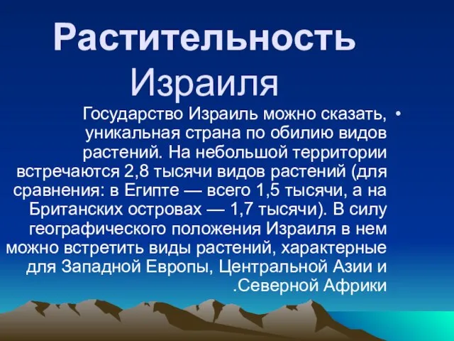 Растительность Израиля
 Презентация на тему Инклюзивное (включающее) образование
 Что такое FOHOW +? Сетевой маркетинг