- Instruction Manual LX-LC200 toyota ANDROID INTERFACE

Содержание
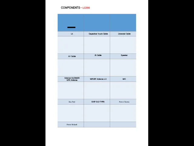
- 2. COMPONENTS – LC200
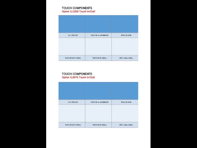
- 3. TOUCH COMPONENTS Option (LC200 Touch In/Out) TOUCH COMPONENTS Option (LX570 Touch In/Out)
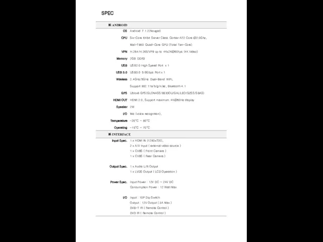
- 4. SPEC
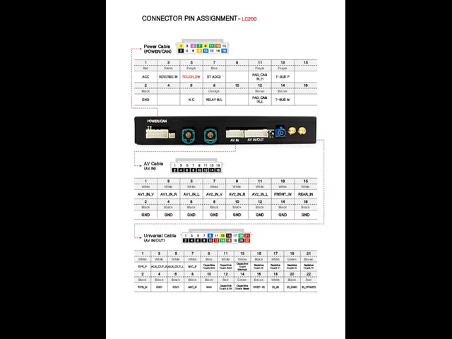
- 5. CONNECTOR PIN ASSIGNMENT – LC200 Power Cable (POWER/CAN) AV Cable (AV IN) Universal Cable (AV IN/OUT)
- 6. DIP S/W INFORMATION – LC200 ON OFF RX200T = RX model small monitor LC200 = TOYOTA
- 7. DIP S/W INFORMATION ON OFF
- 8. POWER CABLE INFORMATION – LC200
- 9. SCREEN VIEW 1 2 3 4 5 6 7 8 9 10 11 12 13
- 10. SCREEN VIEW – Split Screen Mode Long Press Normal Mode Split Screen Mode Mode ※ Split
- 11. OEM BUTTON USAGE 3 1 2 4 6 5 LX570 (2016 - 2018)) LC200 1 2
- 12. OEM BUTTON USAGE 1 4 RX200T LX570 (2013 - 2015) 1 2 3 4 5 6
- 13. CONNECT CAN/POWER DIAGRAM GVIF IN GVIF OUT Original cable LEXUS-A100 w/o NAVI - 2 ※ Connect
- 14. CONNECT CAN/POWER CONNECTOR Connect ‘CAN High/Low" to the original connector from supplied connector ※ Depending on
- 15. CONNECT CAN/POWER CONNECTOR Remove original connector. Connect supplied connector to audio and original connector. ※ Depending
- 16. TOUCH CABLE DIAGRAM – LC200 / LX570 Monitor Out FFC Cable Original FFC Cable WIFI/BT GPS
- 17. MONITOR FFC SETTING – LC200 Cut off the supplied FFC cable
- 18. MONITOR FFC SETTING – LX570
- 19. CONNECT LVDS IN/OUT Remove white connector on behind of monitor. Cut plastic of white connector and
- 20. CONNECT LVDS IN/OUT Cut wiring number 11. ※ RX200T Remove blue connector on behind of monitor.
- 21. DVB-T CONNECTION DIAGRAM FOR AV INPUT A 1 2 3 4 1 2 3 4 UNIVERSAL
- 22. DVB-T CONNECTION DIAGRAM FOR ASUKA UNIVERSAL CABLE AV CABLE Use Joystick of Car as mouse for
- 23. ADD REMOTE CONTROLLER K-PAD REMOTE MODEL Setting Remote select Remote Memory Selected remote control setting Enter
- 24. TOUCH PAD GESTURE -RX Click Push Joystick and release Scroll Push Joystick and move Joystick to
- 25. HEADREST MONITOR ※ Headrest Monitor (HDMI Out) HDMI
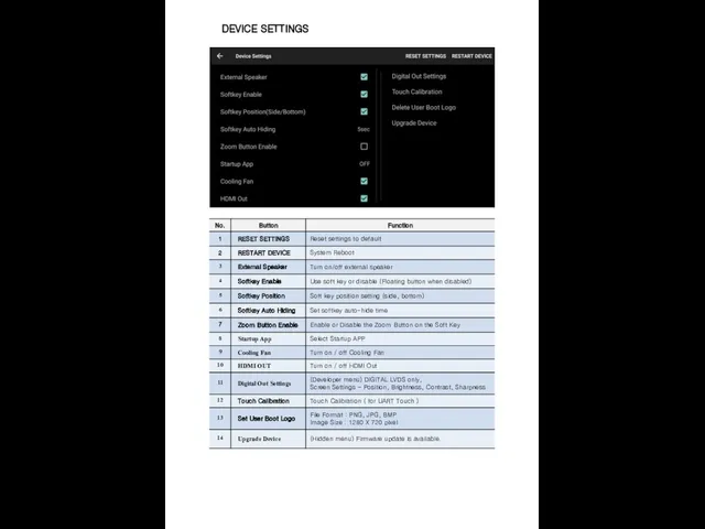
- 26. DEVICE SETTINGS
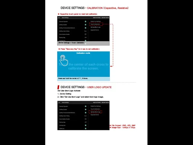
- 27. DEVICE SETTINGS – CALIBRATION (Capacitive, Resistive) ※ Capacitive touch panel no need set calibration Set User
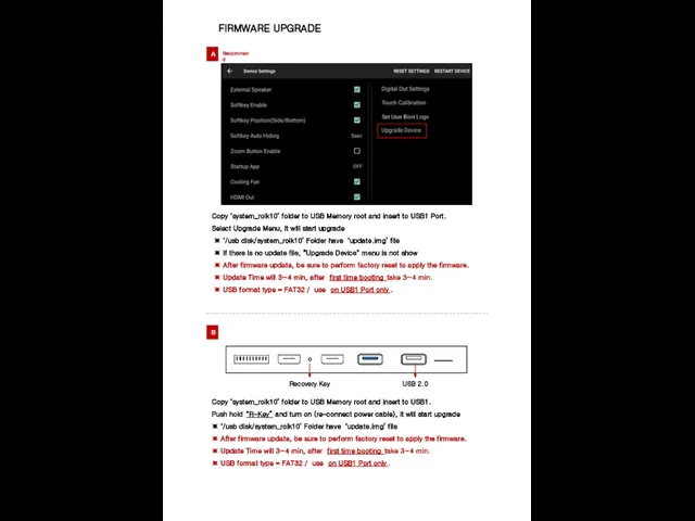
- 28. FIRMWARE UPGRADE Copy ‘system_roik10’ folder to USB Memory root and insert to USB1 Port. Select Upgrade
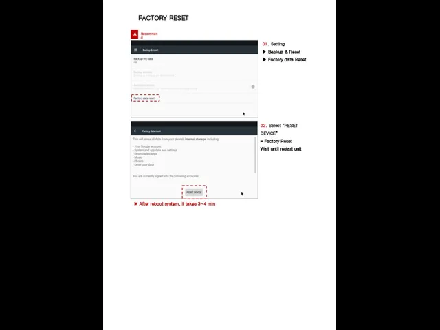
- 29. FACTORY RESET A Recommend 01. Setting ▶ Backup & Reset ▶ Factory data Reset 02. Select
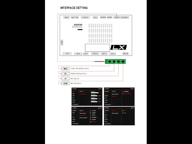
- 30. INTERFACE SETTING MENU SEL UP DOWN Enter the setting menu Select setting menu Moving Up Moving
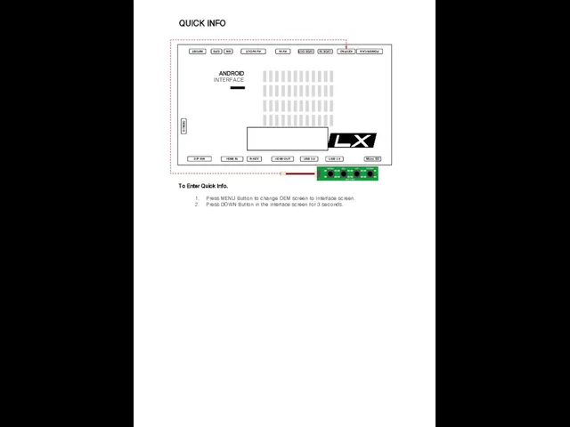
- 31. QUICK INFO To Enter Quick Info. Press MENU Button to change OEM screen to Interface screen.
- 33. Скачать презентацию
Слайд 3TOUCH COMPONENTS
Option (LC200 Touch In/Out)
TOUCH COMPONENTS
Option (LX570 Touch In/Out)
TOUCH COMPONENTS
Option (LC200 Touch In/Out)
TOUCH COMPONENTS
Option (LX570 Touch In/Out)
Слайд 4SPEC
SPEC
Слайд 5CONNECTOR PIN ASSIGNMENT – LC200
Power Cable
(POWER/CAN)
AV Cable
(AV IN)
Universal Cable
(AV IN/OUT)
POWER/CAN
AV IN
AV IN/OUT
CONNECTOR PIN ASSIGNMENT – LC200
Power Cable
(POWER/CAN)
AV Cable
(AV IN)
Universal Cable
(AV IN/OUT)
POWER/CAN
AV IN
AV IN/OUT
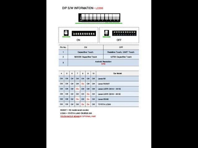
Слайд 6DIP S/W INFORMATION – LC200
ON
OFF
RX200T = RX model small monitor
LC200 = TOYOTA
DIP S/W INFORMATION – LC200
ON
OFF
RX200T = RX model small monitor
LC200 = TOYOTA
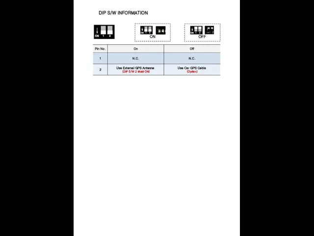
Слайд 7DIP S/W INFORMATION
ON
OFF
DIP S/W INFORMATION
ON
OFF
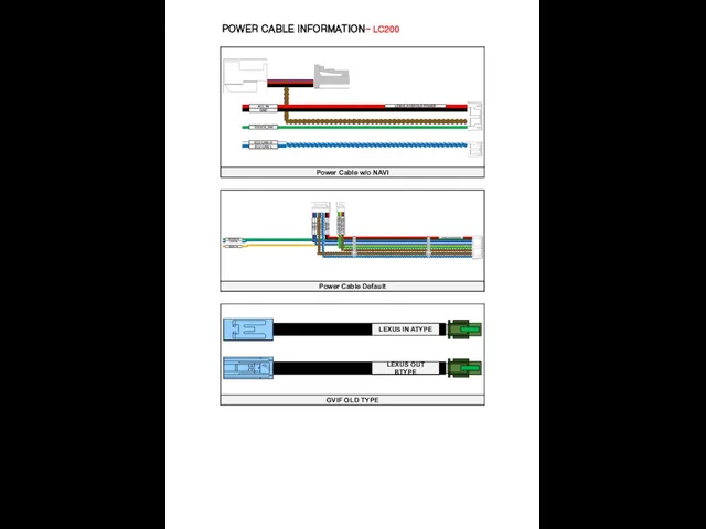
Слайд 8POWER CABLE INFORMATION – LC200
POWER CABLE INFORMATION – LC200
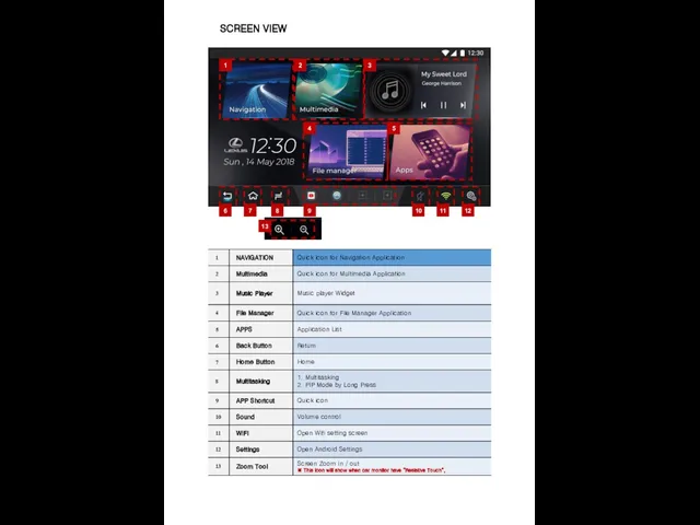
Слайд 9SCREEN VIEW
1
2
3
4
5
6
7
8
9
10
11
12
13
SCREEN VIEW
1
2
3
4
5
6
7
8
9
10
11
12
13
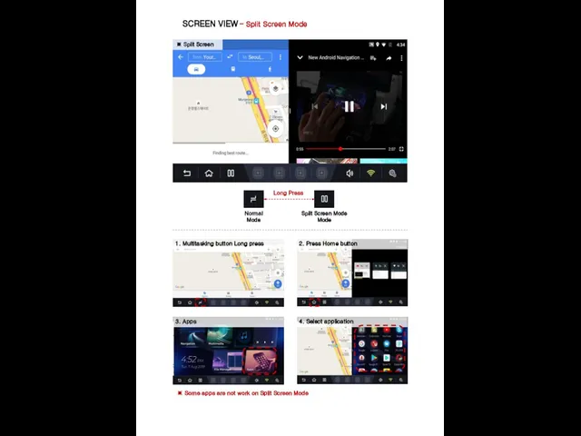
Слайд 10SCREEN VIEW – Split Screen Mode
Long Press
Normal
Mode
Split Screen Mode
Mode
※ Split Screen
1. Multitasking
SCREEN VIEW – Split Screen Mode
Long Press
Normal
Mode
Split Screen Mode
Mode
※ Split Screen
1. Multitasking
Слайд 11OEM BUTTON USAGE
3
1
2
4
6
5
LX570 (2016 - 2018))
LC200
1
2
3
4
5
6
OEM BUTTON USAGE
3
1
2
4
6
5
LX570 (2016 - 2018))
LC200
1
2
3
4
5
6
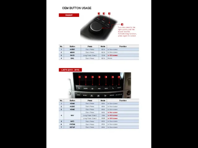
Слайд 12OEM BUTTON USAGE
1
4
RX200T
LX570 (2013 - 2015)
1
2
3
4
5
6
2
3
Turn the wheel to the right quickly
OEM BUTTON USAGE
1
4
RX200T
LX570 (2013 - 2015)
1
2
3
4
5
6
2
3
Turn the wheel to the right quickly
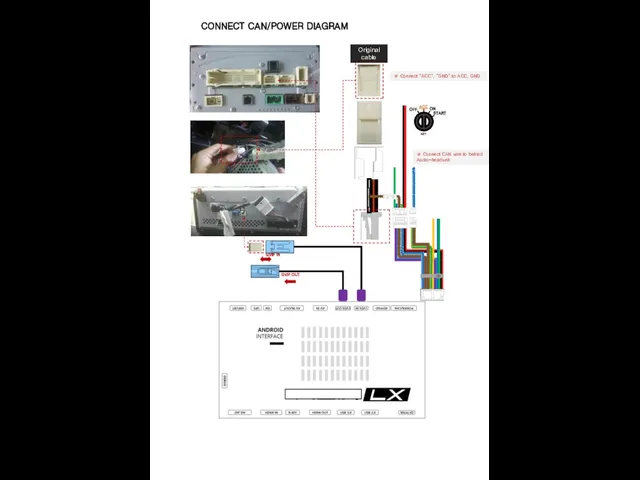
Слайд 13CONNECT CAN/POWER DIAGRAM
GVIF IN
GVIF OUT
Original cable
LEXUS-A100 w/o NAVI - 2
※ Connect “ACC”,
CONNECT CAN/POWER DIAGRAM
GVIF IN
GVIF OUT
Original cable
LEXUS-A100 w/o NAVI - 2
※ Connect “ACC”,
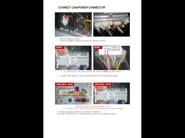
Слайд 14CONNECT CAN/POWER CONNECTOR
Connect ‘CAN High/Low" to the original connector from supplied connector
※
CONNECT CAN/POWER CONNECTOR
Connect ‘CAN High/Low" to the original connector from supplied connector
※
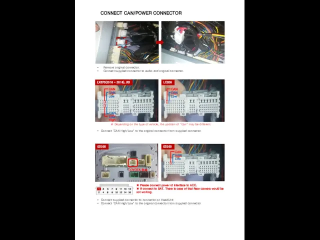
Слайд 15CONNECT CAN/POWER CONNECTOR
Remove original connector.
Connect supplied connector to audio and original
CONNECT CAN/POWER CONNECTOR
Remove original connector.
Connect supplied connector to audio and original
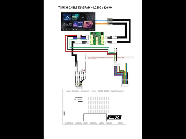
Слайд 16TOUCH CABLE DIAGRAM – LC200 / LX570
Monitor Out FFC Cable
Original FFC Cable
WIFI/BT
GPS
POWER/CAN
AV
TOUCH CABLE DIAGRAM – LC200 / LX570
Monitor Out FFC Cable
Original FFC Cable
WIFI/BT
GPS
POWER/CAN
AV
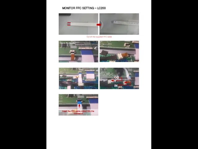
Слайд 17MONITOR FFC SETTING – LC200
Cut off the supplied FFC cable
MONITOR FFC SETTING – LC200
Cut off the supplied FFC cable
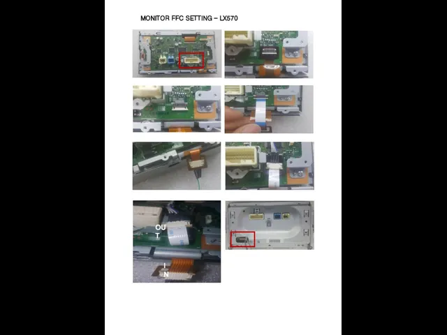
Слайд 18MONITOR FFC SETTING – LX570
MONITOR FFC SETTING – LX570
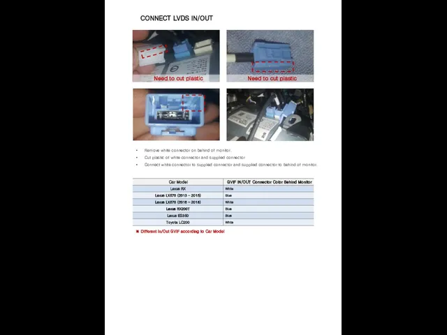
Слайд 19CONNECT LVDS IN/OUT
Remove white connector on behind of monitor.
Cut plastic of white
CONNECT LVDS IN/OUT
Remove white connector on behind of monitor.
Cut plastic of white
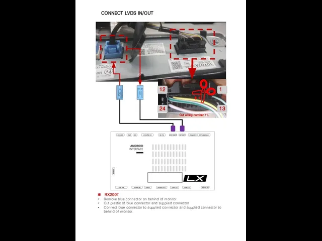
Слайд 20CONNECT LVDS IN/OUT
Cut wiring number 11.
※ RX200T
Remove blue connector on behind
CONNECT LVDS IN/OUT
Cut wiring number 11.
※ RX200T
Remove blue connector on behind
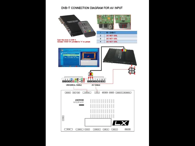
Слайд 21DVB-T CONNECTION DIAGRAM FOR AV INPUT
A
1
2
3
4
1
2
3
4
UNIVERSAL CABLE
AV CABLE
Open the cover of DVB-T.
Connect
DVB-T CONNECTION DIAGRAM FOR AV INPUT
A
1
2
3
4
1
2
3
4
UNIVERSAL CABLE
AV CABLE
Open the cover of DVB-T.
Connect
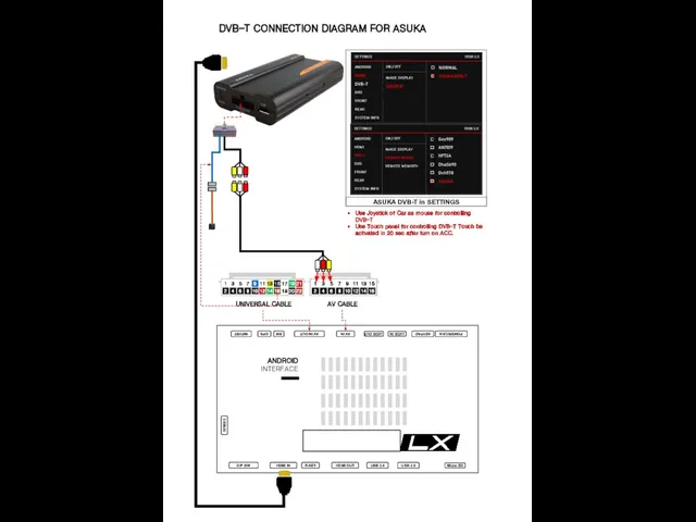
Слайд 22DVB-T CONNECTION DIAGRAM FOR ASUKA
UNIVERSAL CABLE
AV CABLE
Use Joystick of Car as mouse
DVB-T CONNECTION DIAGRAM FOR ASUKA
UNIVERSAL CABLE
AV CABLE
Use Joystick of Car as mouse
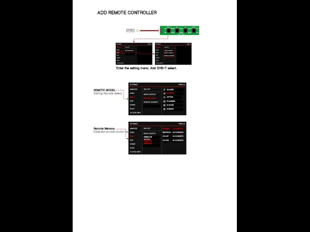
Слайд 23ADD REMOTE CONTROLLER
K-PAD
REMOTE MODEL
Setting Remote select
Remote Memory
Selected remote control setting
Enter the
ADD REMOTE CONTROLLER
K-PAD
REMOTE MODEL
Setting Remote select
Remote Memory
Selected remote control setting
Enter the
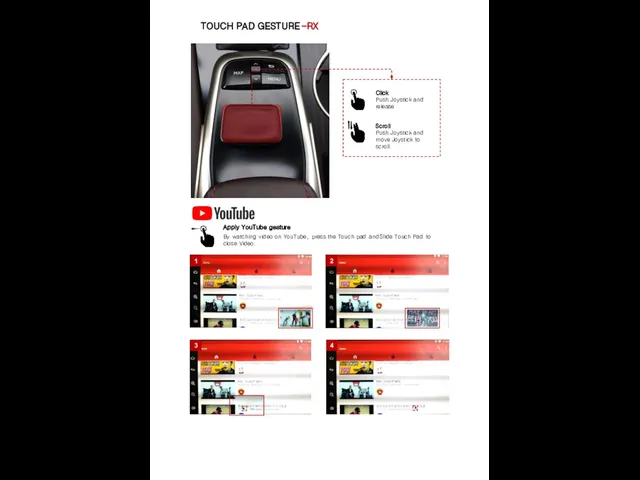
Слайд 24TOUCH PAD GESTURE -RX
Click
Push Joystick and release
Scroll
Push Joystick and move Joystick to
TOUCH PAD GESTURE -RX
Click
Push Joystick and release
Scroll
Push Joystick and move Joystick to
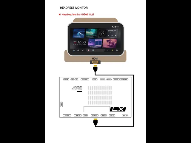
Слайд 25HEADREST MONITOR
※ Headrest Monitor (HDMI Out)
HDMI
HEADREST MONITOR
※ Headrest Monitor (HDMI Out)
HDMI
Слайд 26DEVICE SETTINGS
DEVICE SETTINGS
Слайд 27DEVICE SETTINGS – CALIBRATION (Capacitive, Resistive)
※ Capacitive touch panel no need set
DEVICE SETTINGS – CALIBRATION (Capacitive, Resistive)
※ Capacitive touch panel no need set
Слайд 28FIRMWARE UPGRADE
Copy ‘system_roik10’ folder to USB Memory root and insert to USB1
FIRMWARE UPGRADE
Copy ‘system_roik10’ folder to USB Memory root and insert to USB1
Слайд 29FACTORY RESET
A
Recommend
01. Setting
▶ Backup & Reset
▶ Factory data Reset
02.
FACTORY RESET
A
Recommend
01. Setting
▶ Backup & Reset
▶ Factory data Reset
02.
Слайд 30INTERFACE SETTING
MENU
SEL
UP
DOWN
Enter the setting menu
Select setting menu
Moving Up
Moving Down
INTERFACE SETTING
MENU
SEL
UP
DOWN
Enter the setting menu
Select setting menu
Moving Up
Moving Down
Слайд 31QUICK INFO
To Enter Quick Info.
Press MENU Button to change OEM screen to
QUICK INFO
To Enter Quick Info.
Press MENU Button to change OEM screen to
 Реляционная модель данных Реляционная модель
 Good Building. Проект
 Тульский самовар
 Центрально-Черноземный район
 Разработка и подготовка к сборке вертикально-сверлильного станка
 Журналистские расследования
 Фондовый рынок
 Презентация на тему Влияние позиции воспитателя в формировании активной познавательной деятельности дошкольника
 Поручение Президента РФ
 Презентация на тему Природа в искусстве
  НАЧАЛО ВТОРОЙ МИРОВОЙ ВОЙНЫ.
 Действия с фрагментами рисунка
 Преимущества предлагаемой технологии сухого совместного помола для цеха мелких силикатных блоков 1. Снижение расхода цемента на 1
  Методы психодиагностики в работе с женщинами на разных этапах формирования материнской роли
 Проблемы фискальной и монетарной политики
 Муниципальное общеобразовательное учреждение Беломорского муниципального района «Беломорская открытая (сменная) общеобразоват
 Осторожно, СПАМ!
 Презентация на тему Имя твоё – женщина
 Дизайн-проект
 ЖК Друзья - Соседи
 Интегральная защитная система Блаурок
 Официально-деловой стиль речи
 ÐанÑÑие 1-1 (ÐекÑиÑ) дÐÑ Ð¡ÐÐ
 Модернизация системы электроснабжения складского терминала
 Тренажер знаний о наречии
 Пять проваленных стартапов
 Studying abroad
 Razumovskiy