- Metallurgy of the welded joint

Содержание
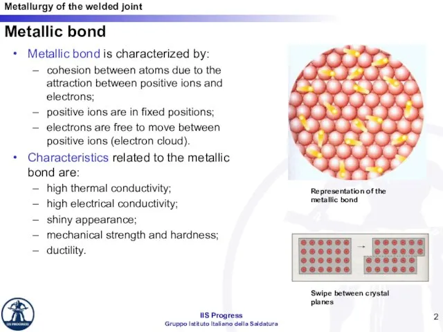
- 2. Metallic bond Metallic bond is characterized by: cohesion between atoms due to the attraction between positive
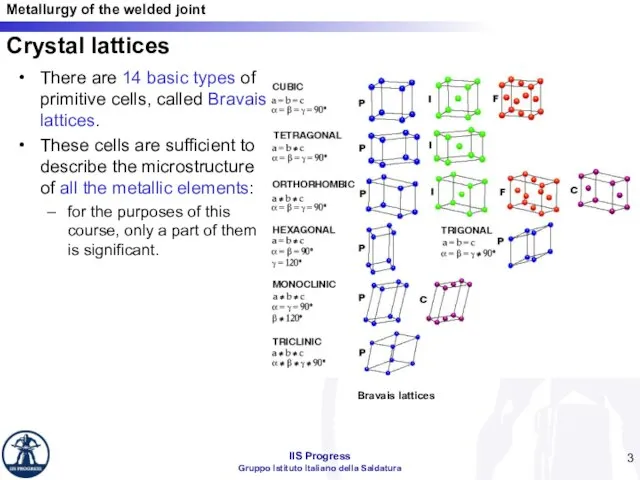
- 3. There are 14 basic types of primitive cells, called Bravais lattices. These cells are sufficient to
- 4. Monomorphic and polymorphic metallic materials The metallic elements can be divided into: monomorphic elements: always have
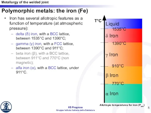
- 5. Iron has several allotropic features as a function of temperature (at atmospheric pressure): delta (δ) iron,
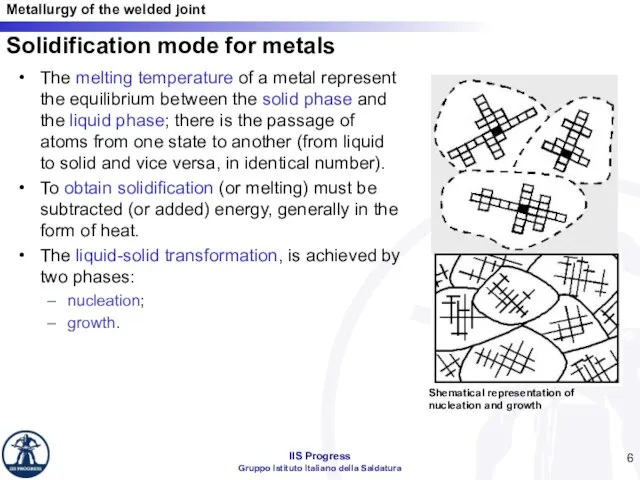
- 6. Solidification mode for metals The melting temperature of a metal represent the equilibrium between the solid
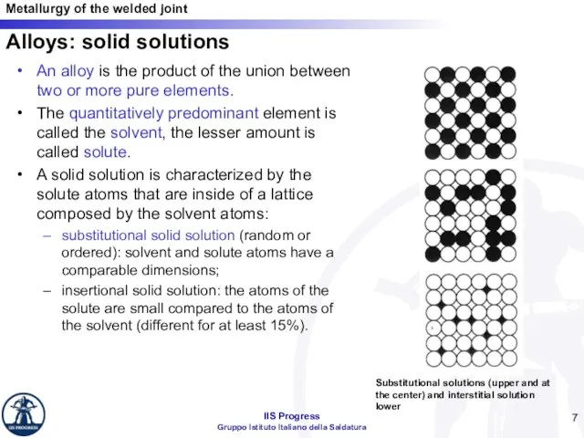
- 7. Alloys: solid solutions An alloy is the product of the union between two or more pure
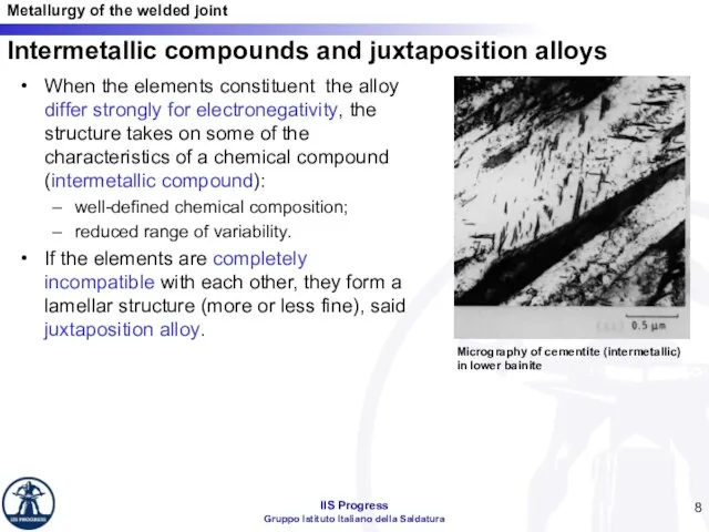
- 8. Intermetallic compounds and juxtaposition alloys When the elements constituent the alloy differ strongly for electronegativity, the
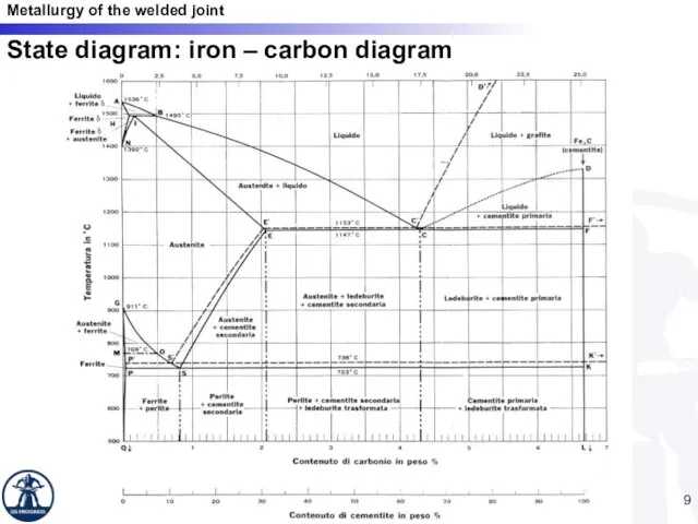
- 9. State diagram: iron – carbon diagram
- 10. Cooling speed It’s the main parameter that influences the transformations at the solid state. For carbon
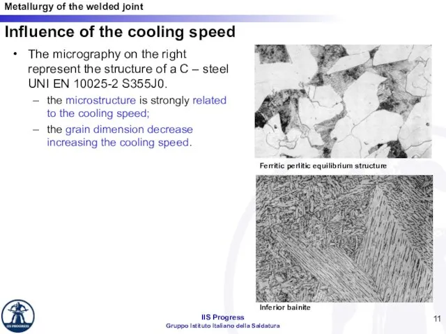
- 11. Influence of the cooling speed The micrography on the right represent the structure of a C
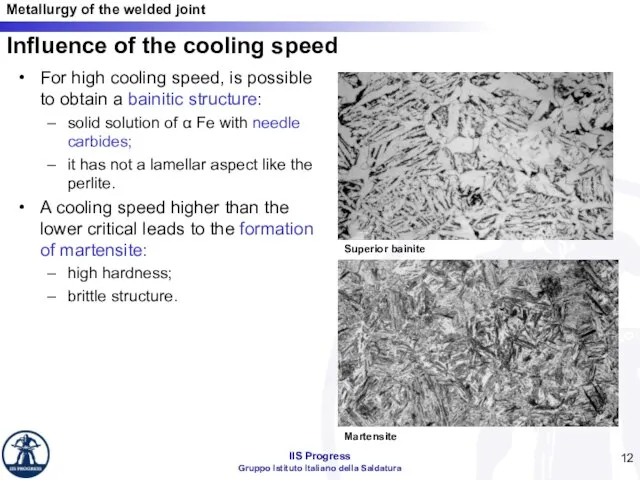
- 12. For high cooling speed, is possible to obtain a bainitic structure: solid solution of α Fe
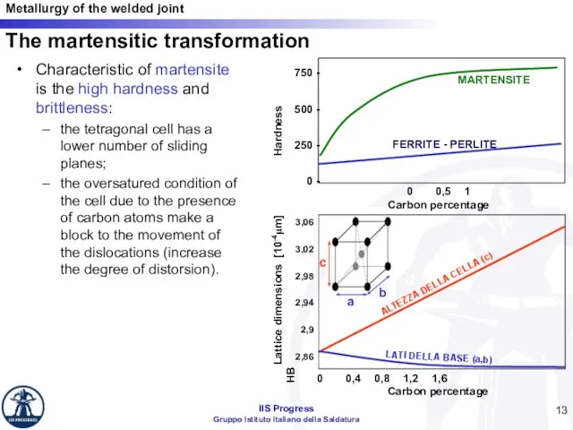
- 13. Characteristic of martensite is the high hardness and brittleness: the tetragonal cell has a lower number
- 14. The equivalent carbon On the basis of the chemical composition this parameter defines the quenchability of
- 15. Welding thermal cycle Factors influencing the thermal cycle: Heat input Combined thickness Preheat temperature Consequences of
- 16. Thermal Cycle /18
- 17. /18 Metallurgical effects: structure of the welded joint
- 18. /18 Weld Metal - Composition Dilution ratio (Rd), is used ti evaluate chemical composition of the
- 19. /18 Metallurgical structure of the weld metal Welding direction Welding direction The final microstructure of a
- 20. /18 Metallurgical structure of the weld metal Weld metal dendritic microstructure
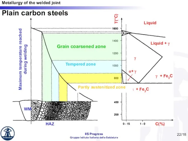
- 21. /18 Heat Affected Zone The heat-affected zone, includes those regions that are measurably influenced by the
- 22. /18 C(%) T(°C) Liquid Liquid + γ γ γ + Fe3C α + Fe3C α+ γ
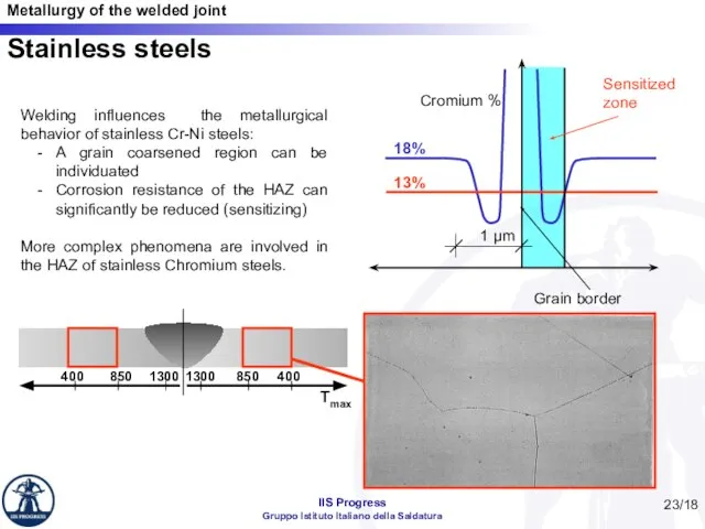
- 23. /18 Stainless steels Welding influences the metallurgical behavior of stainless Cr-Ni steels: A grain coarsened region
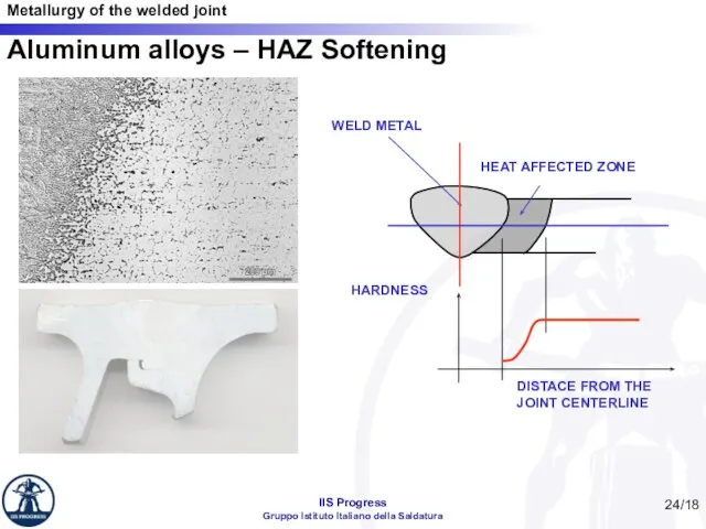
- 24. /18 Aluminum alloys – HAZ Softening
- 25. The feasibility of welding a particular metal or alloy. A number of factors affect weldability including
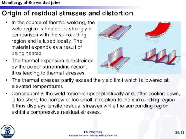
- 26. Origin of residual stresses and distortion In the course of thermal welding, the weld region is
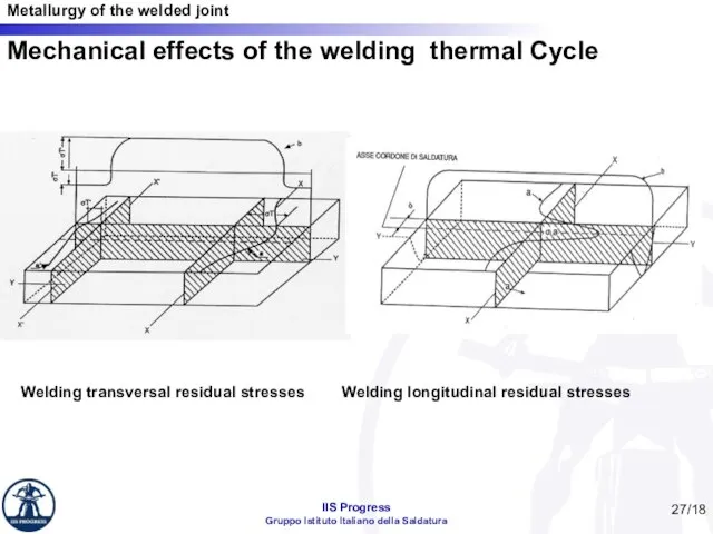
- 27. Mechanical effects of the welding thermal Cycle Welding transversal residual stresses Welding longitudinal residual stresses /18
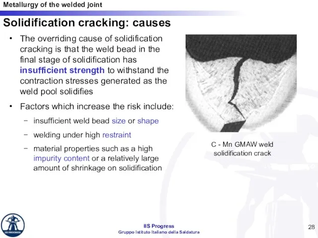
- 28. Solidification cracking: causes The overriding cause of solidification cracking is that the weld bead in the
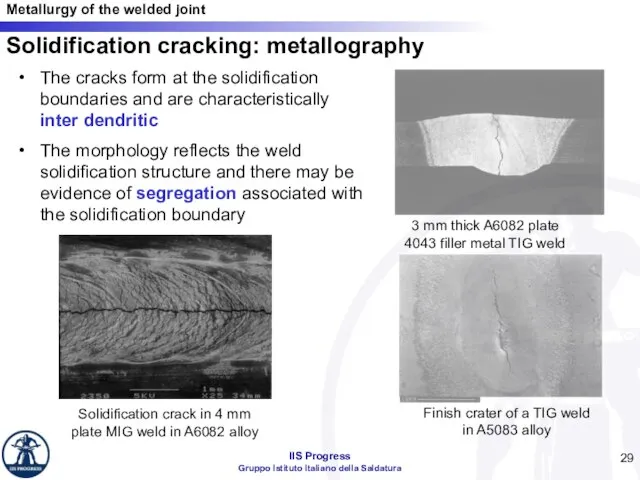
- 29. Solidification cracking: metallography The cracks form at the solidification boundaries and are characteristically inter dendritic The
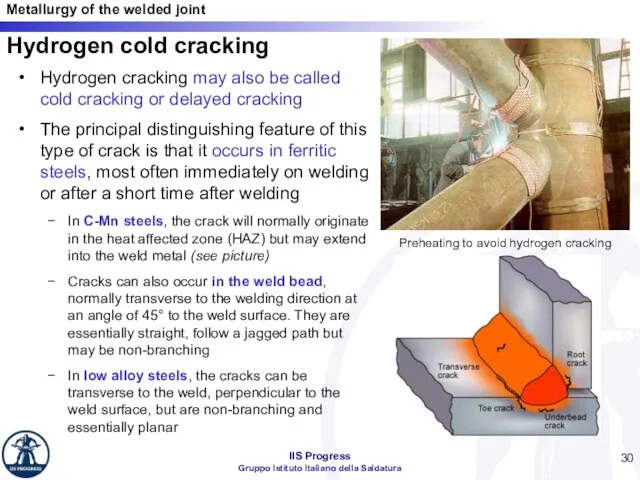
- 30. Hydrogen cold cracking Hydrogen cracking may also be called cold cracking or delayed cracking The principal
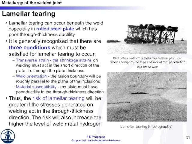
- 31. Lamellar tearing Lamellar tearing can occur beneath the weld especially in rolled steel plate which has
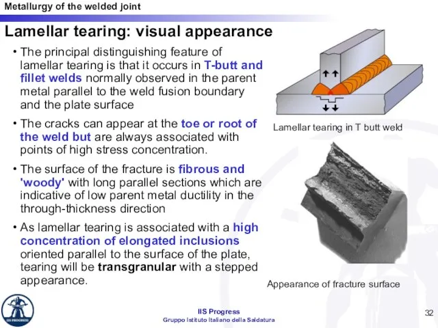
- 32. Lamellar tearing: visual appearance The principal distinguishing feature of lamellar tearing is that it occurs in
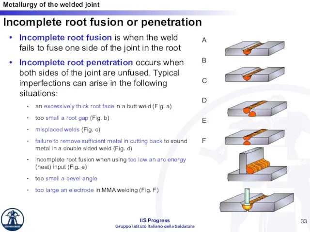
- 33. Incomplete root fusion or penetration Incomplete root fusion is when the weld fails to fuse one
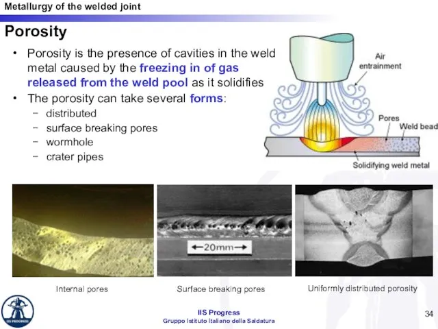
- 34. Porosity Porosity is the presence of cavities in the weld metal caused by the freezing in
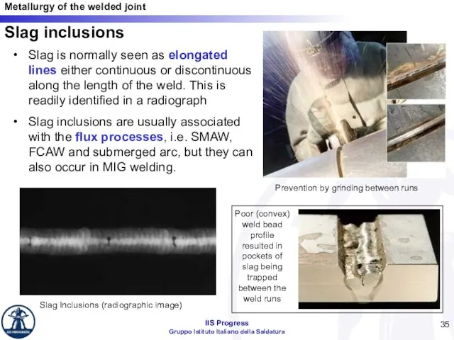
- 35. Slag inclusions Slag is normally seen as elongated lines either continuous or discontinuous along the length
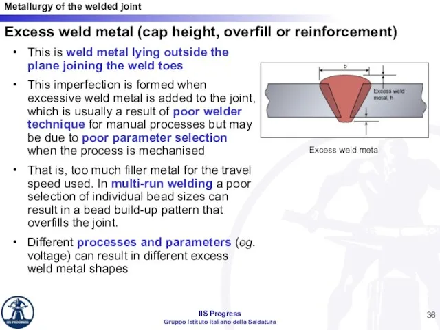
- 36. Excess weld metal (cap height, overfill or reinforcement) This is weld metal lying outside the plane
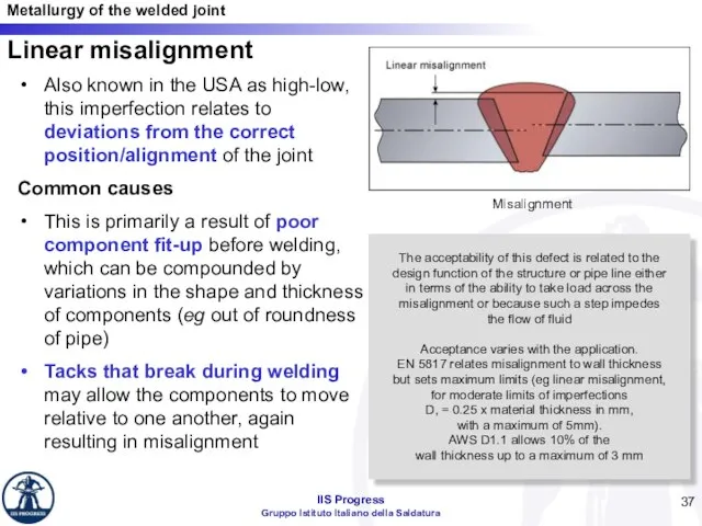
- 37. Linear misalignment Also known in the USA as high-low, this imperfection relates to deviations from the
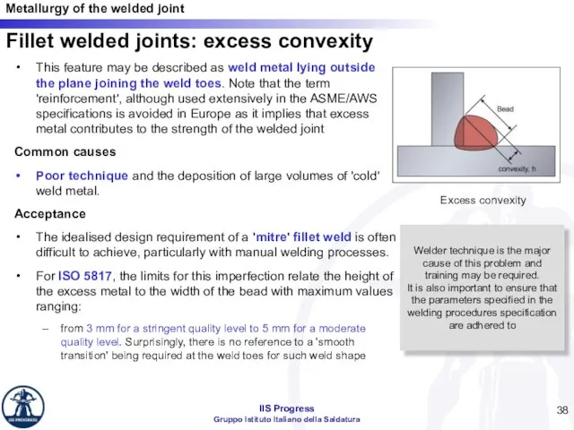
- 38. Fillet welded joints: excess convexity This feature may be described as weld metal lying outside the
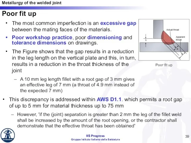
- 39. Poor fit up The most common imperfection is an excessive gap between the mating faces of
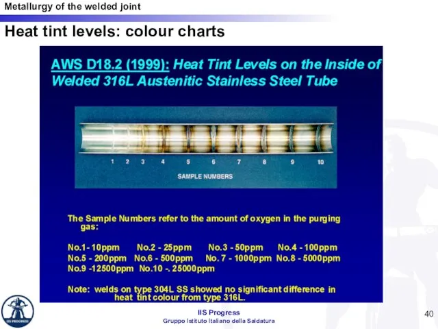
- 40. Heat tint levels: colour charts
- 42. Скачать презентацию
Слайд 3There are 14 basic types of primitive cells, called Bravais lattices.
These cells
There are 14 basic types of primitive cells, called Bravais lattices.
These cells
Слайд 4Monomorphic and polymorphic metallic materials
The metallic elements can be divided into:
monomorphic elements:
Monomorphic and polymorphic metallic materials
The metallic elements can be divided into:
monomorphic elements:
Слайд 5Iron has several allotropic features as a function of temperature (at atmospheric
Iron has several allotropic features as a function of temperature (at atmospheric
Слайд 6Solidification mode for metals
The melting temperature of a metal represent the equilibrium
Solidification mode for metals
The melting temperature of a metal represent the equilibrium
Слайд 7Alloys: solid solutions
An alloy is the product of the union between two
Alloys: solid solutions
An alloy is the product of the union between two
Слайд 8Intermetallic compounds and juxtaposition alloys
When the elements constituent the alloy differ strongly
Intermetallic compounds and juxtaposition alloys
When the elements constituent the alloy differ strongly
Слайд 9State diagram: iron – carbon diagram
State diagram: iron – carbon diagram
Слайд 10Cooling speed
It’s the main parameter that influences the transformations at the solid state.
For carbon steels and low
Cooling speed
It’s the main parameter that influences the transformations at the solid state.
For carbon steels and low
Слайд 11Influence of the cooling speed
The micrography on the right represent the structure
Influence of the cooling speed
The micrography on the right represent the structure
Слайд 12For high cooling speed, is possible to obtain a bainitic structure:
solid solution
For high cooling speed, is possible to obtain a bainitic structure:
solid solution
Слайд 13Characteristic of martensite is the high hardness and brittleness:
the tetragonal cell has
Characteristic of martensite is the high hardness and brittleness:
the tetragonal cell has
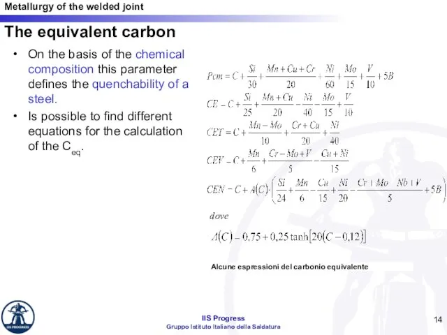
Слайд 14The equivalent carbon
On the basis of the chemical composition this parameter defines
The equivalent carbon
On the basis of the chemical composition this parameter defines
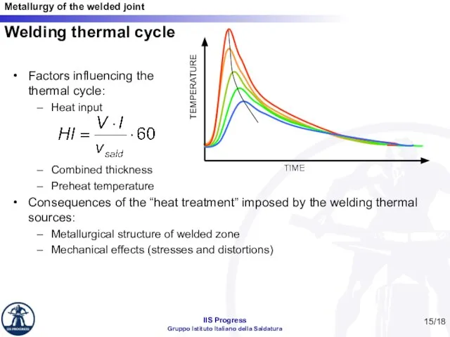
Слайд 15Welding thermal cycle
Factors influencing the
thermal cycle:
Heat input
Combined thickness
Preheat temperature
Consequences of the
Welding thermal cycle
Factors influencing the
thermal cycle:
Heat input
Combined thickness
Preheat temperature
Consequences of the
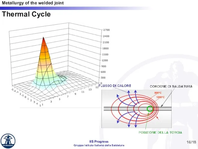
Слайд 16Thermal Cycle
/18
Thermal Cycle
/18
Слайд 17/18
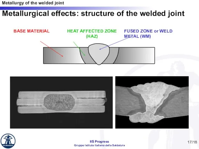
Metallurgical effects: structure of the welded joint
/18
Metallurgical effects: structure of the welded joint
Слайд 18/18
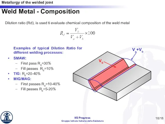
Weld Metal - Composition
Dilution ratio (Rd), is used ti evaluate chemical composition
/18
Weld Metal - Composition
Dilution ratio (Rd), is used ti evaluate chemical composition
Слайд 19/18
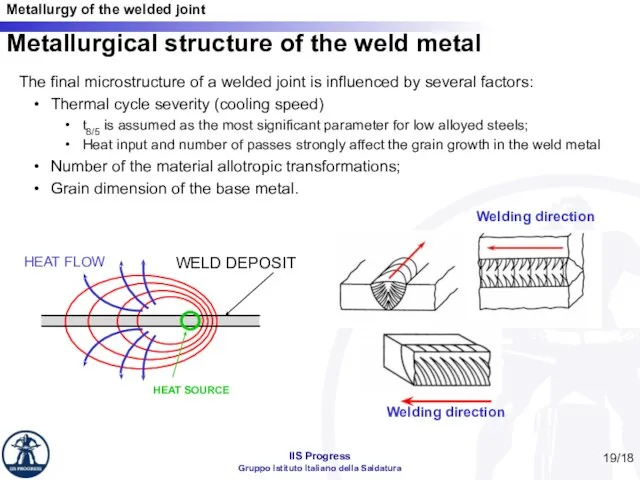
Metallurgical structure of the weld metal
Welding direction
Welding direction
The final microstructure of a
/18
Metallurgical structure of the weld metal
Welding direction
Welding direction
The final microstructure of a
Слайд 20/18
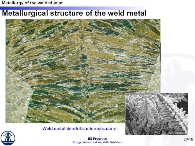
Metallurgical structure of the weld metal
Weld metal dendritic microstructure
/18
Metallurgical structure of the weld metal
Weld metal dendritic microstructure
Слайд 21/18
Heat Affected Zone
The heat-affected zone, includes those regions that are measurably influenced
/18
Heat Affected Zone
The heat-affected zone, includes those regions that are measurably influenced
Слайд 22/18
C(%)
T(°C)
Liquid
Liquid + γ
γ
γ + Fe3C
α + Fe3C
α+ γ
Maximum temperature reached during welding
WM
HAZ
Plain
/18
C(%)
T(°C)
Liquid
Liquid + γ
γ
γ + Fe3C
α + Fe3C
α+ γ
Maximum temperature reached during welding
WM
HAZ
Plain
Слайд 23/18
Stainless steels
Welding influences the metallurgical behavior of stainless Cr-Ni steels:
A grain coarsened
/18
Stainless steels
Welding influences the metallurgical behavior of stainless Cr-Ni steels:
A grain coarsened
Слайд 24/18
Aluminum alloys – HAZ Softening
/18
Aluminum alloys – HAZ Softening
Слайд 25The feasibility of welding a particular metal or alloy.
A number of factors
The feasibility of welding a particular metal or alloy.
A number of factors
Слайд 26Origin of residual stresses and distortion
In the course of thermal welding, the
weld
Origin of residual stresses and distortion
In the course of thermal welding, the weld
Слайд 27Mechanical effects of the welding thermal Cycle
Welding transversal residual stresses Welding longitudinal residual
Mechanical effects of the welding thermal Cycle
Welding transversal residual stresses Welding longitudinal residual
Слайд 28Solidification cracking: causes
The overriding cause of solidification cracking is that the weld
Solidification cracking: causes
The overriding cause of solidification cracking is that the weld
Слайд 29Solidification cracking: metallography
The cracks form at the solidification boundaries and are characteristically
Solidification cracking: metallography
The cracks form at the solidification boundaries and are characteristically
Слайд 30Hydrogen cold cracking
Hydrogen cracking may also be called cold cracking or delayed
Hydrogen cold cracking
Hydrogen cracking may also be called cold cracking or delayed
Слайд 31Lamellar tearing
Lamellar tearing can occur beneath the weld especially in rolled steel
Lamellar tearing
Lamellar tearing can occur beneath the weld especially in rolled steel
Слайд 32Lamellar tearing: visual appearance
The principal distinguishing feature of lamellar tearing is that
Lamellar tearing: visual appearance
The principal distinguishing feature of lamellar tearing is that
Слайд 33Incomplete root fusion or penetration
Incomplete root fusion is when the weld fails
Incomplete root fusion or penetration
Incomplete root fusion is when the weld fails
Слайд 34Porosity
Porosity is the presence of cavities in the weld metal caused by
Porosity
Porosity is the presence of cavities in the weld metal caused by
Слайд 35Slag inclusions
Slag is normally seen as elongated lines either continuous or discontinuous
Slag inclusions
Slag is normally seen as elongated lines either continuous or discontinuous
Слайд 36Excess weld metal (cap height, overfill or reinforcement)
This is weld metal lying
Excess weld metal (cap height, overfill or reinforcement)
This is weld metal lying
Слайд 37Linear misalignment
Also known in the USA as high-low, this imperfection relates to
Linear misalignment
Also known in the USA as high-low, this imperfection relates to
Слайд 38Fillet welded joints: excess convexity
This feature may be described as weld metal
Fillet welded joints: excess convexity
This feature may be described as weld metal
Слайд 39Poor fit up
The most common imperfection is an excessive gap between the
Poor fit up
The most common imperfection is an excessive gap between the
Слайд 40Heat tint levels: colour charts
Heat tint levels: colour charts
 Характеристика детей с ЗПР. Неблагоприятные семейные факторы влияющие на ребенка с ЗПР
 road monitoring 2020
 Круги на полях
 Основные различия между руководителем по теории «Х» и по теории «Y»
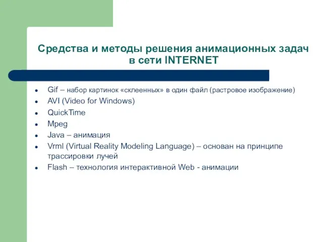 Средства и методы решения анимационных задачв сети INTERNET
 Презентация на тему ЛАТВИЯ
 Развитие общества
 18.02.2008 г.
 Луг и его обитатели
 Стратегия по всем каналам: индивидуальный подход к каждому партнеру
 Пути реализации инклюзивного образования средствами инновационной деятельности
 Документационное обеспечение управления и фукционирование организации
 Игрушки из полхов-майдана
 Ювенальная юстиция «за» и «против»
 С Днём матери
 Графики линейных функций
 Презентация на тему Влияние солнечной активности на процессы, происходящие на Земле
  ICN Holding
 Феномен канона в искусстве Древнего Египта
 Общество как сложная динамичная система
 Социальные сети Презентацию разработала ученица 11 класса «А» Рязанова Анастасия.
 New Jersey Employment Law Attorneys
 Willst du glücklich sein im Leben, trage bei zu andrer Glück, denn die Freude, die wir geben, kehrt ins eigene Herz zurück. Willst du glücklich sein im. - презентация
 Образ матери в искусстве
 Гиподинамия
  Здоровье, как его сберечь
 Презентация на тему Возникновение искусства и религиозных верований
  Городской центр социальных и спортивных программ г. Севастополя Детско-юношеский клуб Салют