Method improvements polymer mud to improve data transmission quality on hydraulic communication channel
- Method improvements polymer mud to improve data transmission quality on hydraulic communication channel

Содержание
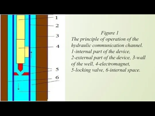
- 2. Figure 1 The principle of operation of the hydraulic communication channel. 1-internal part of the device,
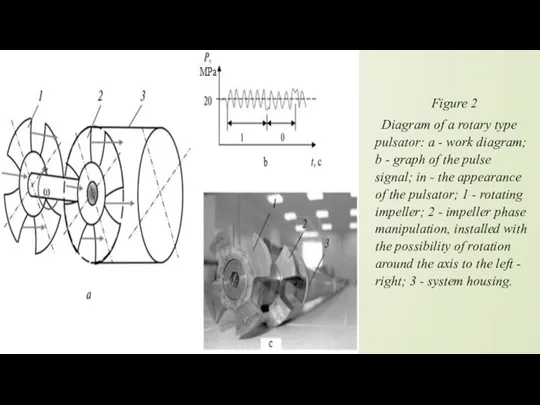
- 3. Figure 2 Diagram of a rotary type pulsator: a - work diagram; b - graph of
- 4. Figure 3 Coding signals in the hydraulic communication channel
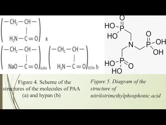
- 5. Figure 4. Scheme of the structures of the molecules of PAA (a) and hypan (b) Figure
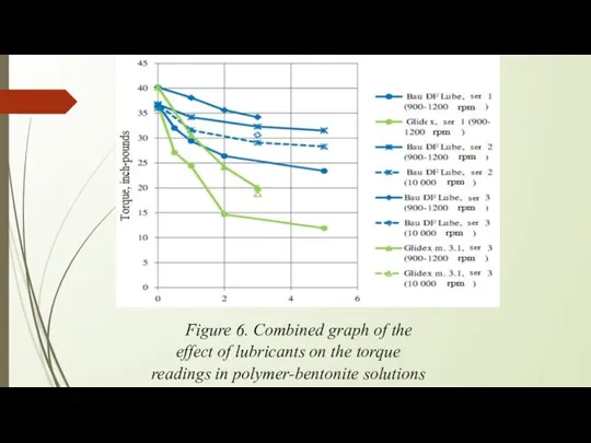
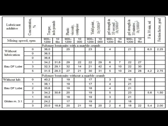
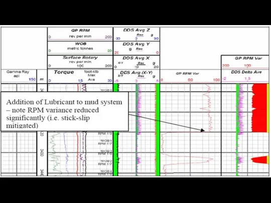
- 6. Figure 6. Combined graph of the effect of lubricants on the torque readings in polymer-bentonite solutions
- 10. Скачать презентацию

 Человек (клиент) сидит в своем офисе
 Mi deporte favorite
 Australia in foreigners’ eyes
 Japan and its culture
 New words
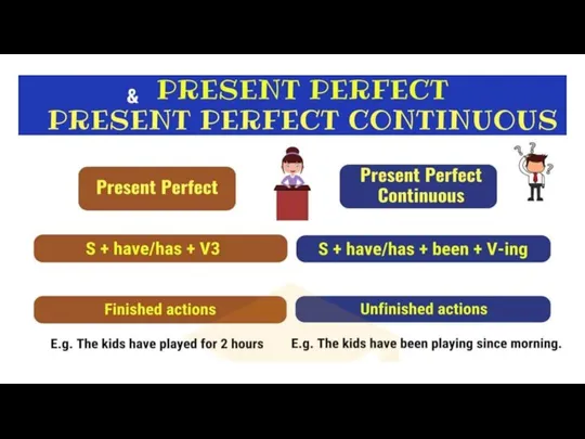 Домашнее задание: Настоящее совершенное - Present Perfect
 Listening and speaking present continuous
 Звуки английской транскрпции
 All about Valentine’s day
 London shops
 Nombres Adjectifs numéraux cardinaux
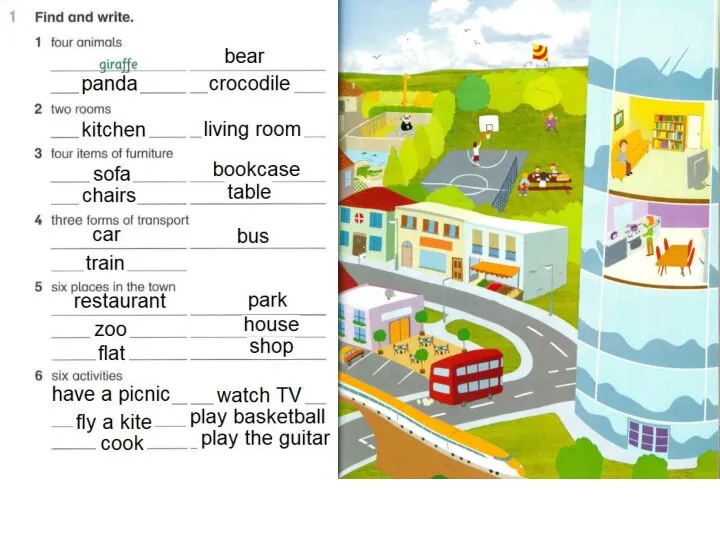 Город. Английский язык
 Have you ever tried these things
 Космическая игра-викторина для 3 класса по английскому языку
 Gadgets
 Types of questions
 Выполнили: Болотина Елена Александровна МОУ СОШ 72 г.Хабаровск 2.Помогайбина Людмила Васильевна МОУ СОШ 72 г.Хабаровск
 Talk for a minute
 International Women's Day. Vocabulary: Seasons, Weather
 The festival Russia Oh, Yes! Food!
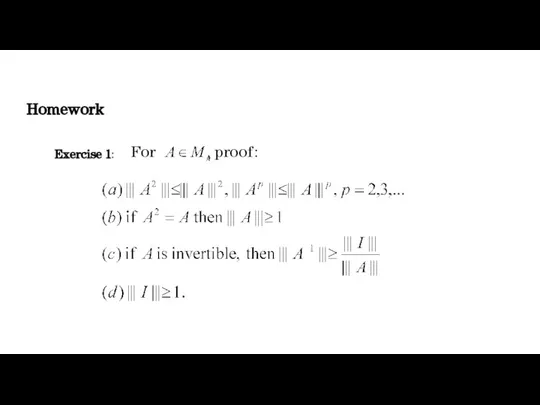 Homework assignment
 Tenses in english. Урок №1
 Fundamental Test Process
 Fruits
 Pet animals. Flashcards
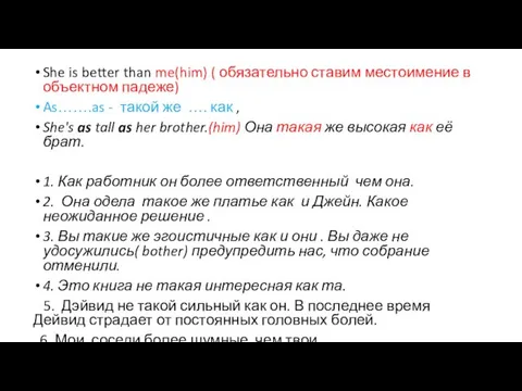 She is better than me (him)
 Language in real world. (Unit 8)
 Презентация на тему МЕСТОИМЕНИЯ HE И IT