- (004)Pulser Testing

Содержание
- 2. © 2001, Halliburton Energy Services, Inc. January 31, 2001 Pulser Testing Objectives At the completion of
- 3. © 2001, Halliburton Energy Services, Inc. January 31, 2001 The Pulser The central component of all
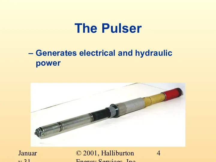
- 4. © 2001, Halliburton Energy Services, Inc. January 31, 2001 The Pulser Generates electrical and hydraulic power
- 5. © 2001, Halliburton Energy Services, Inc. January 31, 2001 Pulser’s Hydraulic Power Operates a poppet/orifice valve
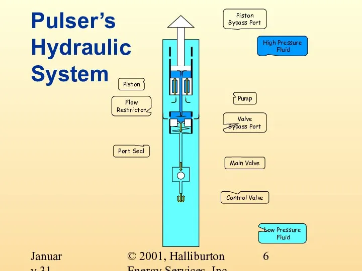
- 6. © 2001, Halliburton Energy Services, Inc. January 31, 2001 Pulser’s Hydraulic System Control Valve Main Valve
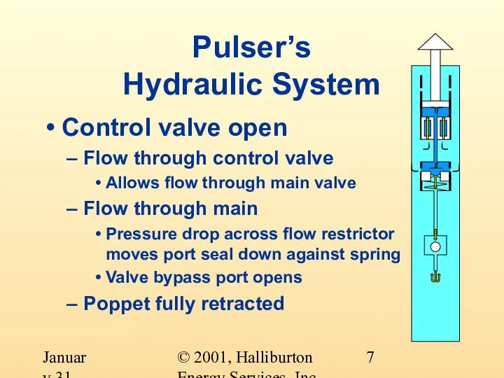
- 7. © 2001, Halliburton Energy Services, Inc. January 31, 2001 Pulser’s Hydraulic System Control valve open Flow
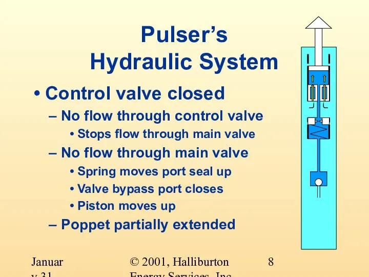
- 8. © 2001, Halliburton Energy Services, Inc. January 31, 2001 Pulser’s Hydraulic System Control valve closed No
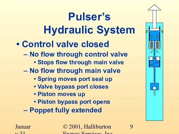
- 9. © 2001, Halliburton Energy Services, Inc. January 31, 2001 Pulser’s Hydraulic System Control valve closed No
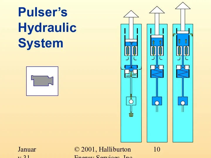
- 10. © 2001, Halliburton Energy Services, Inc. January 31, 2001 Pulser’s Hydraulic System
- 11. © 2001, Halliburton Energy Services, Inc. January 31, 2001 Pulser’s Hydraulic System The control valve is
- 12. © 2001, Halliburton Energy Services, Inc. January 31, 2001 Pulser’s Electrical Power Generator consists of six
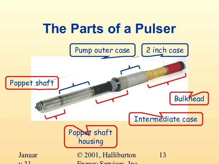
- 13. © 2001, Halliburton Energy Services, Inc. January 31, 2001 The Parts of a Pulser 2 inch
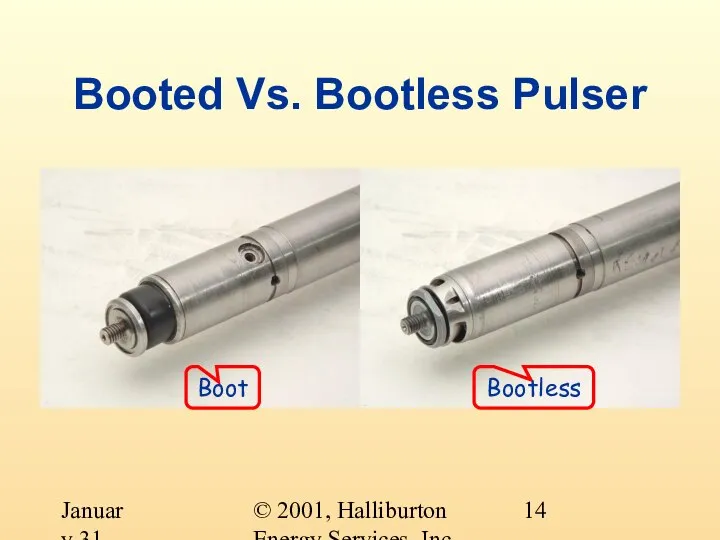
- 14. © 2001, Halliburton Energy Services, Inc. January 31, 2001 Boot Booted Vs. Bootless Pulser Bootless
- 15. © 2001, Halliburton Energy Services, Inc. January 31, 2001 Booted Vs. Bootless Pulser Boot Gas permeable
- 16. © 2001, Halliburton Energy Services, Inc. January 31, 2001 Booted Vs. Bootless Pulser Bootless Increased reliability
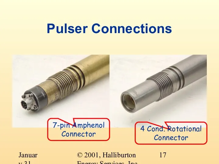
- 17. © 2001, Halliburton Energy Services, Inc. January 31, 2001 Pulser Connections 7-pin Amphenol Connector 4 Cond.
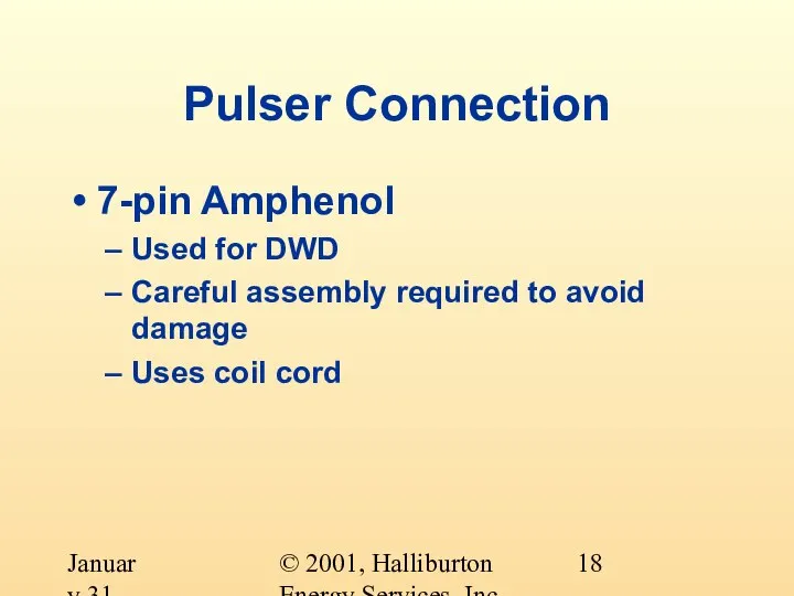
- 18. © 2001, Halliburton Energy Services, Inc. January 31, 2001 Pulser Connection 7-pin Amphenol Used for DWD
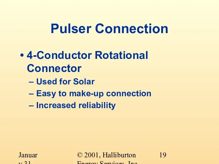
- 19. © 2001, Halliburton Energy Services, Inc. January 31, 2001 Pulser Connection 4-Conductor Rotational Connector Used for
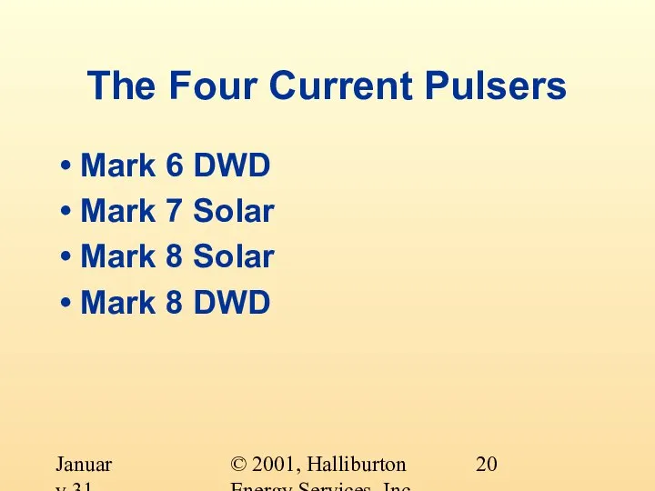
- 20. © 2001, Halliburton Energy Services, Inc. January 31, 2001 The Four Current Pulsers Mark 6 DWD
- 21. © 2001, Halliburton Energy Services, Inc. January 31, 2001 Mark 6 DWD 7-Pin Amphenol Connector Maximum
- 22. © 2001, Halliburton Energy Services, Inc. January 31, 2001 Mark 7 Solar 4-Conductor Rotational Connector Maximum
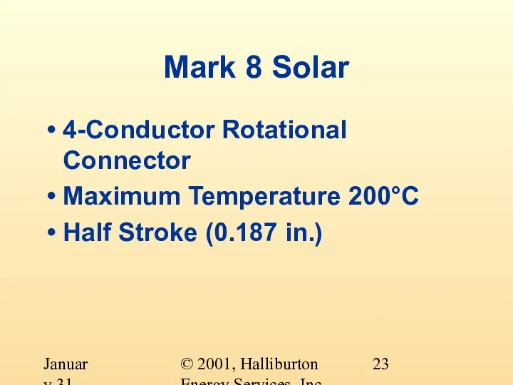
- 23. © 2001, Halliburton Energy Services, Inc. January 31, 2001 Mark 8 Solar 4-Conductor Rotational Connector Maximum
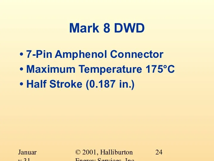
- 24. © 2001, Halliburton Energy Services, Inc. January 31, 2001 Mark 8 DWD 7-Pin Amphenol Connector Maximum
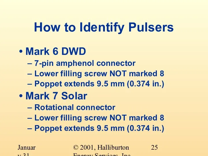
- 25. © 2001, Halliburton Energy Services, Inc. January 31, 2001 How to Identify Pulsers Mark 6 DWD
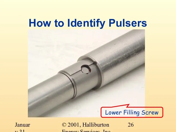
- 26. © 2001, Halliburton Energy Services, Inc. January 31, 2001 How to Identify Pulsers Lower Filling Screw
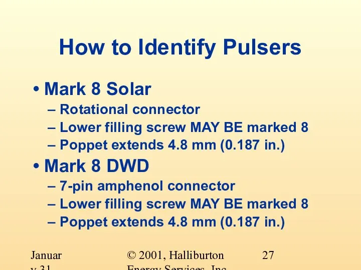
- 27. © 2001, Halliburton Energy Services, Inc. January 31, 2001 How to Identify Pulsers Mark 8 Solar
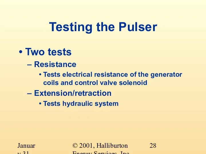
- 28. © 2001, Halliburton Energy Services, Inc. January 31, 2001 Testing the Pulser Two tests Resistance Tests
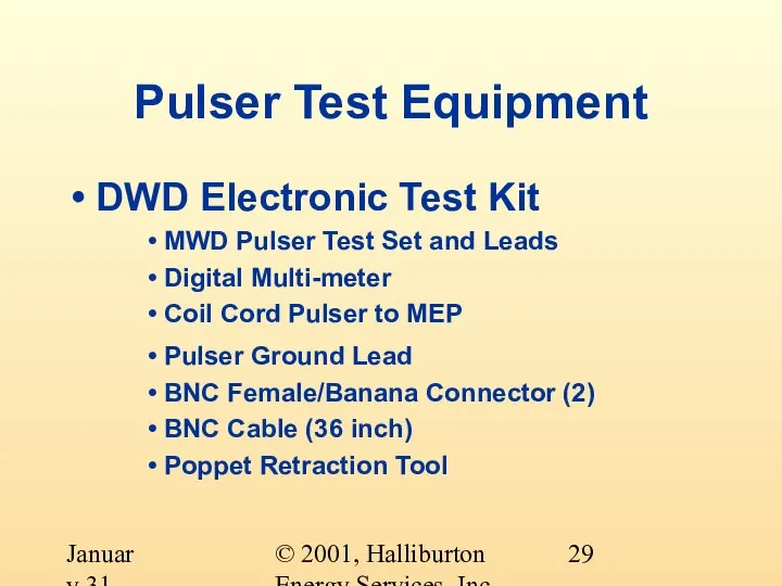
- 29. © 2001, Halliburton Energy Services, Inc. January 31, 2001 Pulser Test Equipment DWD Electronic Test Kit
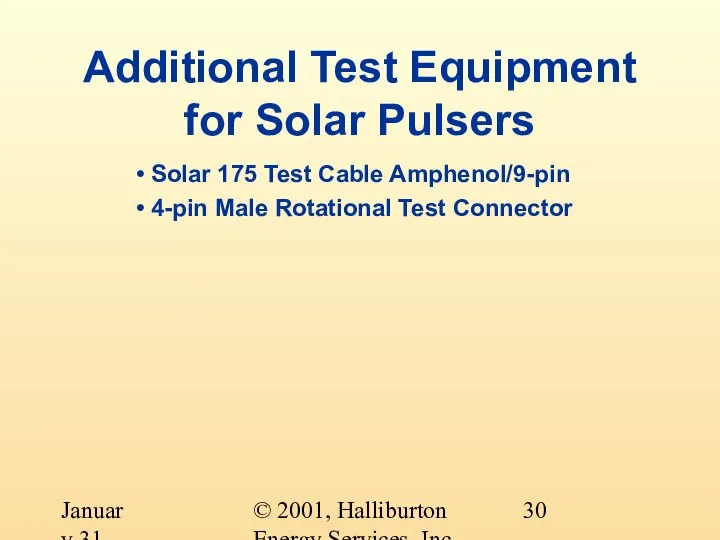
- 30. © 2001, Halliburton Energy Services, Inc. January 31, 2001 Additional Test Equipment for Solar Pulsers Solar
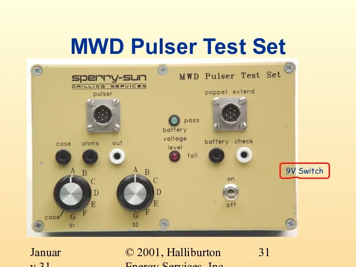
- 31. © 2001, Halliburton Energy Services, Inc. January 31, 2001 MWD Pulser Test Set 9V Switch
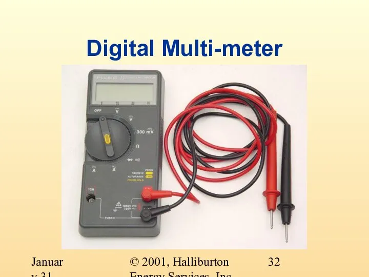
- 32. © 2001, Halliburton Energy Services, Inc. January 31, 2001 Digital Multi-meter
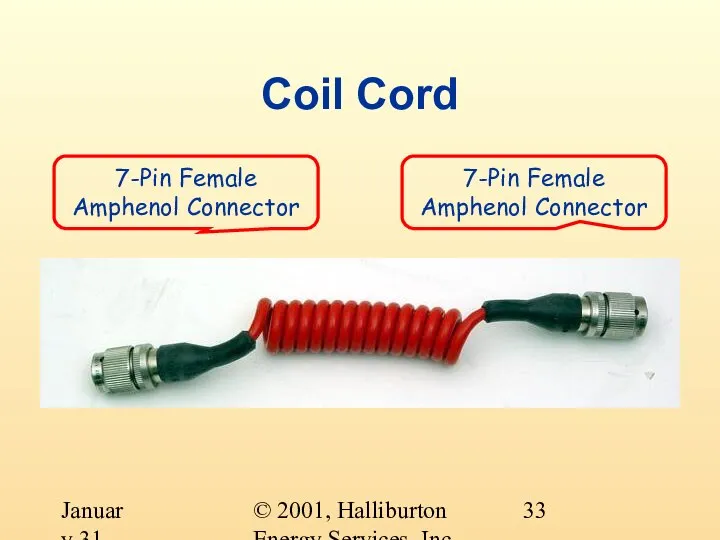
- 33. © 2001, Halliburton Energy Services, Inc. January 31, 2001 Coil Cord 7-Pin Female Amphenol Connector 7-Pin
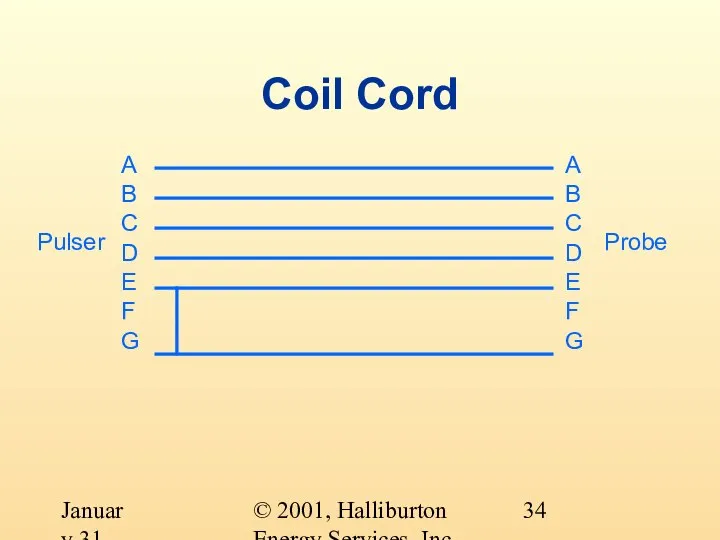
- 34. © 2001, Halliburton Energy Services, Inc. January 31, 2001 Coil Cord A B C D E
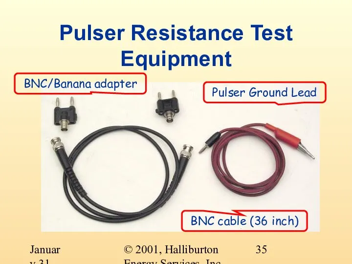
- 35. © 2001, Halliburton Energy Services, Inc. January 31, 2001 Pulser Resistance Test Equipment Pulser Ground Lead
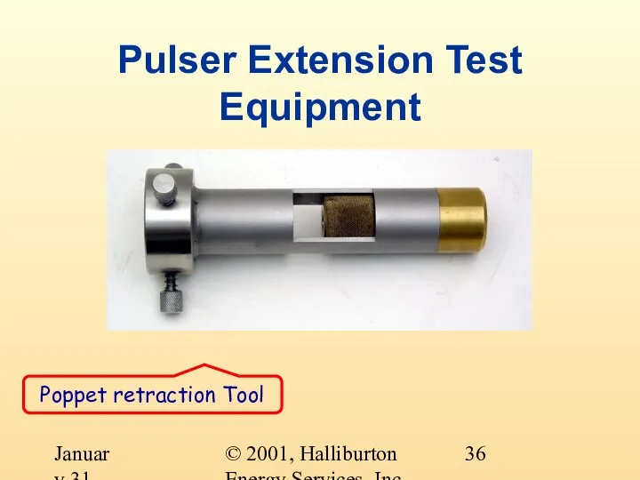
- 36. © 2001, Halliburton Energy Services, Inc. January 31, 2001 Pulser Extension Test Equipment Poppet retraction Tool
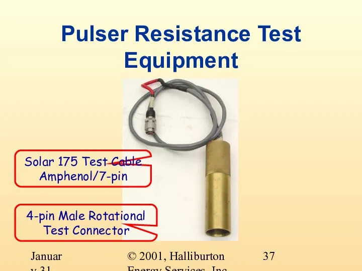
- 37. © 2001, Halliburton Energy Services, Inc. January 31, 2001 Pulser Resistance Test Equipment Solar 175 Test
- 38. © 2001, Halliburton Energy Services, Inc. January 31, 2001 Pulser Resistance Test Purpose Tests the pulser
- 39. © 2001, Halliburton Energy Services, Inc. January 31, 2001 Pulser Resistance Test Procedure Set the 9v
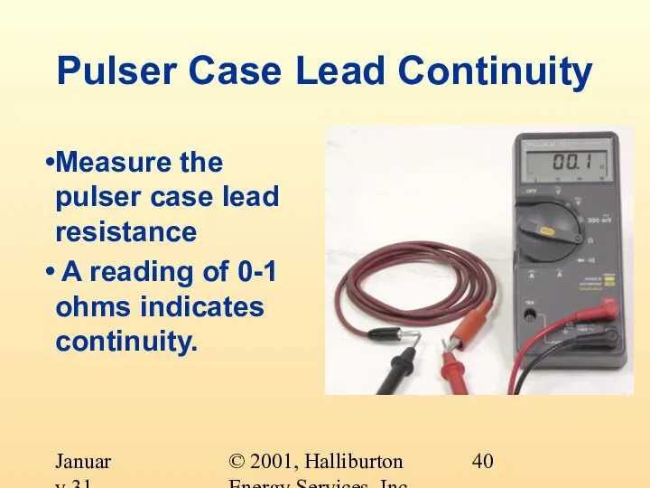
- 40. © 2001, Halliburton Energy Services, Inc. January 31, 2001 Pulser Case Lead Continuity Measure the pulser
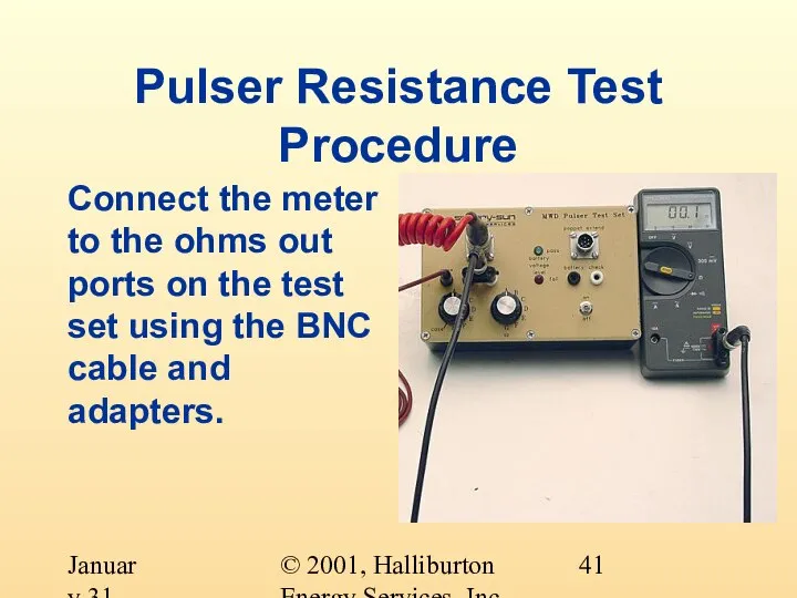
- 41. © 2001, Halliburton Energy Services, Inc. January 31, 2001 Pulser Resistance Test Procedure Connect the meter
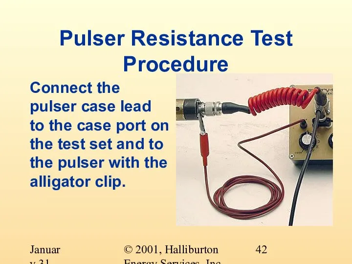
- 42. © 2001, Halliburton Energy Services, Inc. January 31, 2001 Pulser Resistance Test Procedure Connect the pulser
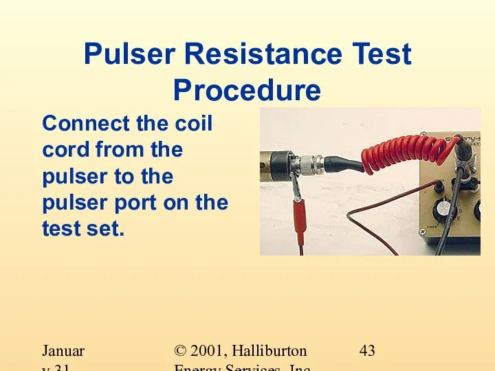
- 43. © 2001, Halliburton Energy Services, Inc. January 31, 2001 Pulser Resistance Test Procedure Connect the coil
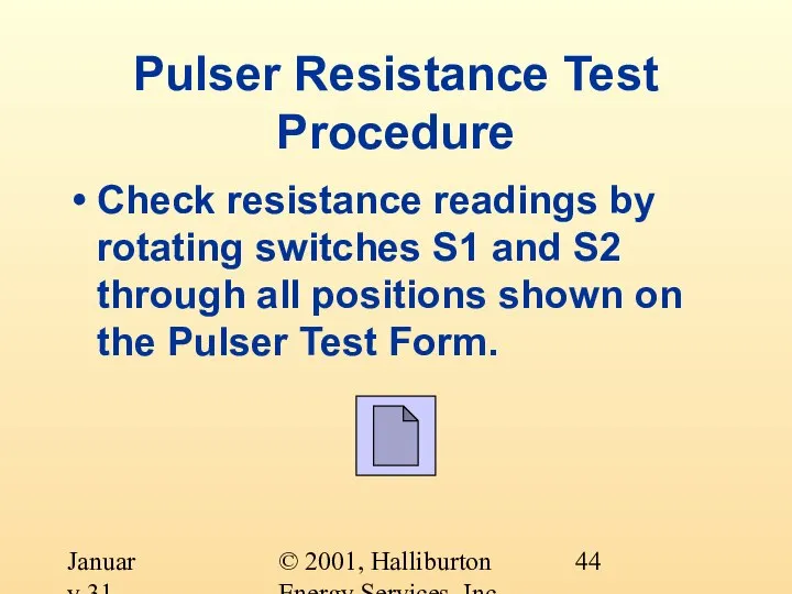
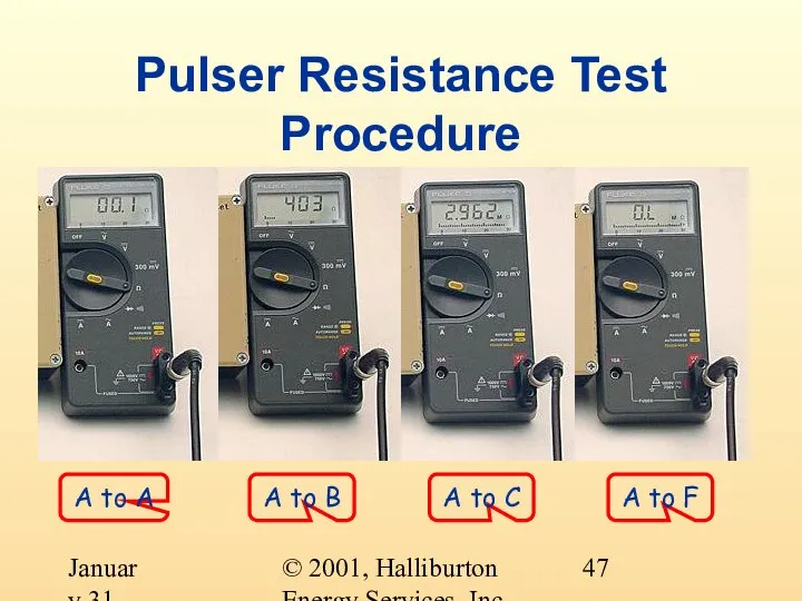
- 44. © 2001, Halliburton Energy Services, Inc. January 31, 2001 Pulser Resistance Test Procedure Check resistance readings
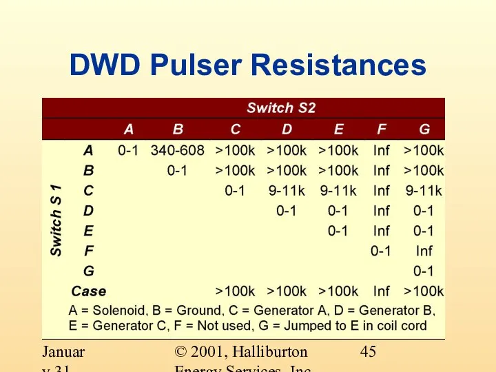
- 45. © 2001, Halliburton Energy Services, Inc. January 31, 2001 DWD Pulser Resistances
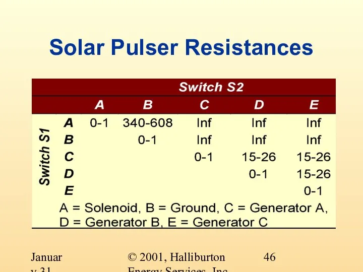
- 46. © 2001, Halliburton Energy Services, Inc. January 31, 2001 Solar Pulser Resistances
- 47. © 2001, Halliburton Energy Services, Inc. January 31, 2001 Pulser Resistance Test Procedure A to A
- 48. © 2001, Halliburton Energy Services, Inc. January 31, 2001 Pulser Resistance Test Procedure If any readings
- 49. © 2001, Halliburton Energy Services, Inc. January 31, 2001 Pulser Resistance Test Procedure What was all
- 50. © 2001, Halliburton Energy Services, Inc. January 31, 2001 Pulser Extension/Retraction Test Purpose Basic test of
- 51. © 2001, Halliburton Energy Services, Inc. January 31, 2001 Pulser Extension/Retraction Test Procedure Clean the pulser;
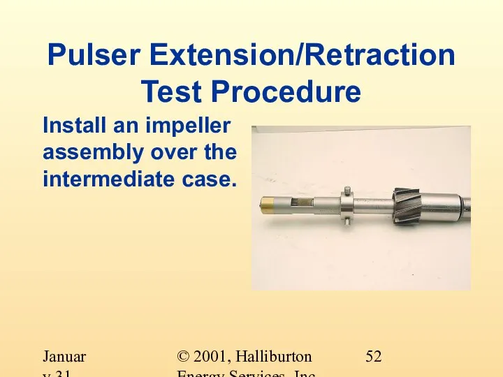
- 52. © 2001, Halliburton Energy Services, Inc. January 31, 2001 Pulser Extension/Retraction Test Procedure Install an impeller
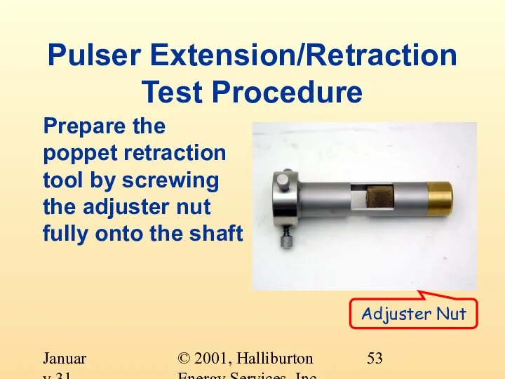
- 53. © 2001, Halliburton Energy Services, Inc. January 31, 2001 Pulser Extension/Retraction Test Procedure Prepare the poppet
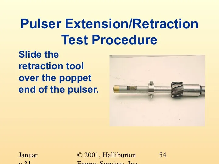
- 54. © 2001, Halliburton Energy Services, Inc. January 31, 2001 Pulser Extension/Retraction Test Procedure Slide the retraction
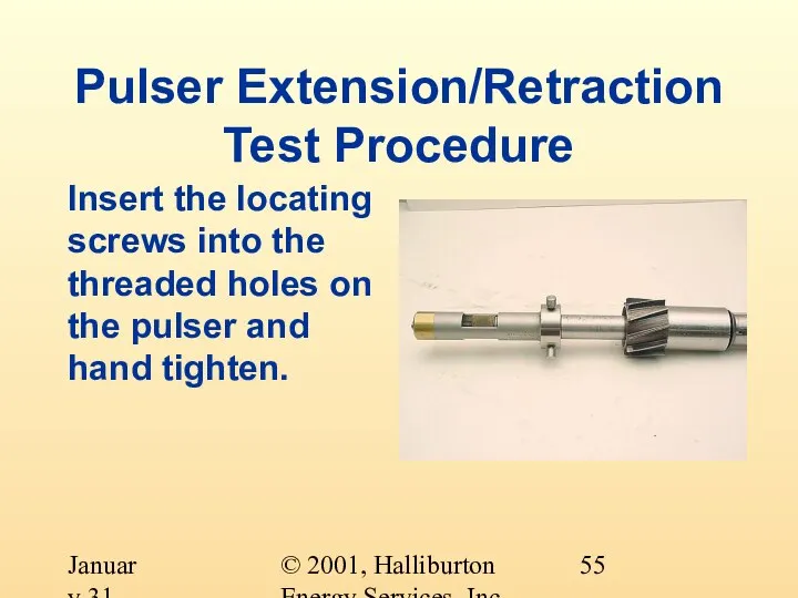
- 55. © 2001, Halliburton Energy Services, Inc. January 31, 2001 Pulser Extension/Retraction Test Procedure Insert the locating
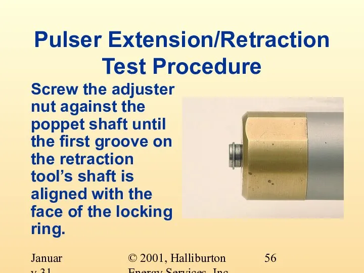
- 56. © 2001, Halliburton Energy Services, Inc. January 31, 2001 Pulser Extension/Retraction Test Procedure Screw the adjuster
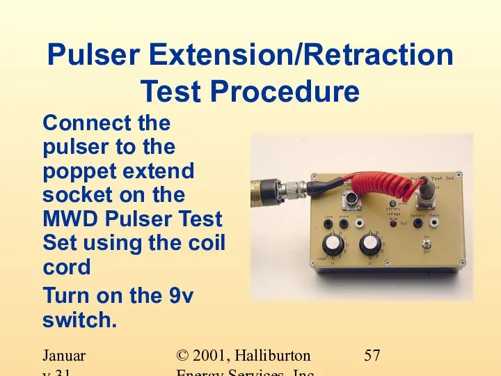
- 57. © 2001, Halliburton Energy Services, Inc. January 31, 2001 Pulser Extension/Retraction Test Procedure Connect the pulser
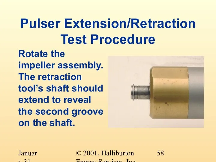
- 58. © 2001, Halliburton Energy Services, Inc. January 31, 2001 Pulser Extension/Retraction Test Procedure Rotate the impeller
- 59. © 2001, Halliburton Energy Services, Inc. January 31, 2001 Pulser Extension/Retraction Test Procedure Monitor the extension;
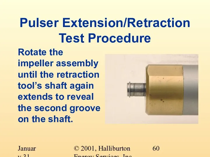
- 60. © 2001, Halliburton Energy Services, Inc. January 31, 2001 Pulser Extension/Retraction Test Procedure Rotate the impeller
- 61. © 2001, Halliburton Energy Services, Inc. January 31, 2001 Pulser Extension/Retraction Test Procedure Turn off the
- 62. © 2001, Halliburton Energy Services, Inc. January 31, 2001 Pulser Extension/Retraction Test Procedure Monitor retraction For
- 63. © 2001, Halliburton Energy Services, Inc. January 31, 2001 Pulser Extension/Retraction Test Procedure Record the results
- 64. © 2001, Halliburton Energy Services, Inc. January 31, 2001 Pulser Extension/Retraction Test Procedure Should the pulser
- 65. © 2001, Halliburton Energy Services, Inc. January 31, 2001 Pulser Extension/Retraction Test Procedure What was all
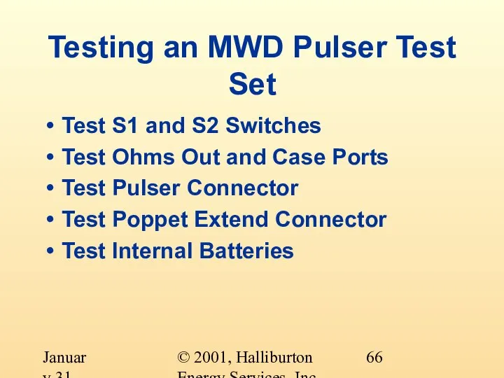
- 66. © 2001, Halliburton Energy Services, Inc. January 31, 2001 Testing an MWD Pulser Test Set Test
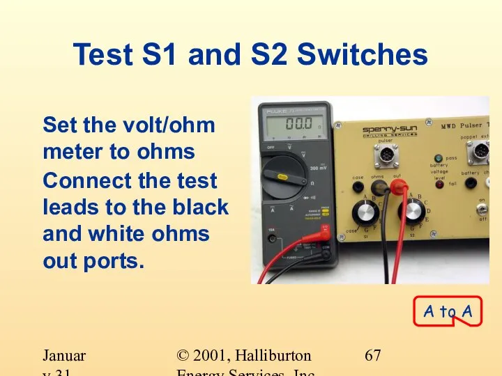
- 67. © 2001, Halliburton Energy Services, Inc. January 31, 2001 Test S1 and S2 Switches Set the
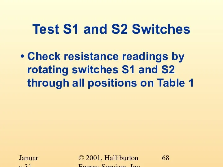
- 68. © 2001, Halliburton Energy Services, Inc. January 31, 2001 Test S1 and S2 Switches Check resistance
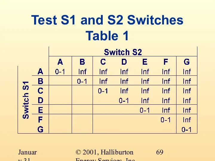
- 69. © 2001, Halliburton Energy Services, Inc. January 31, 2001 Test S1 and S2 Switches Table 1
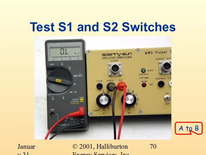
- 70. © 2001, Halliburton Energy Services, Inc. January 31, 2001 Test S1 and S2 Switches A to
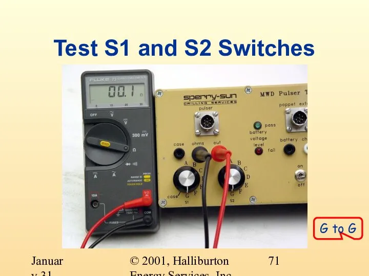
- 71. © 2001, Halliburton Energy Services, Inc. January 31, 2001 Test S1 and S2 Switches G to
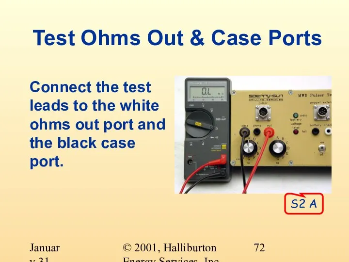
- 72. © 2001, Halliburton Energy Services, Inc. January 31, 2001 Test Ohms Out & Case Ports Connect
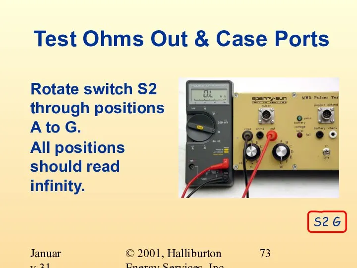
- 73. © 2001, Halliburton Energy Services, Inc. January 31, 2001 Test Ohms Out & Case Ports Rotate
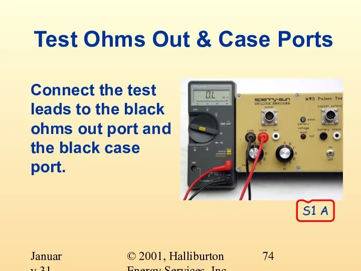
- 74. © 2001, Halliburton Energy Services, Inc. January 31, 2001 Test Ohms Out & Case Ports Connect
- 75. © 2001, Halliburton Energy Services, Inc. January 31, 2001 Test Ohms Out & Case Ports Rotate
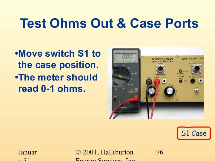
- 76. © 2001, Halliburton Energy Services, Inc. January 31, 2001 Test Ohms Out & Case Ports Move
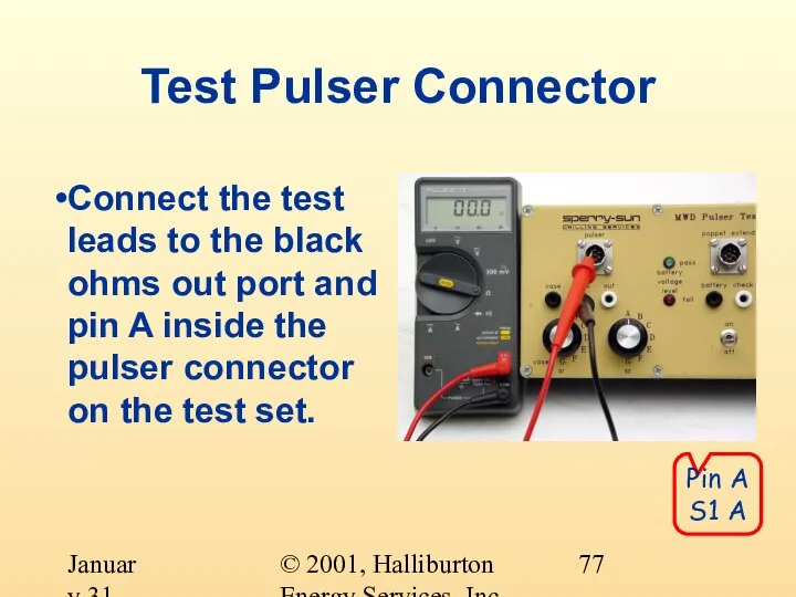
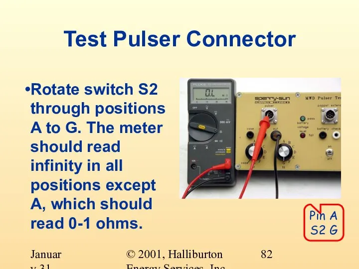
- 77. © 2001, Halliburton Energy Services, Inc. January 31, 2001 Test Pulser Connector Connect the test leads
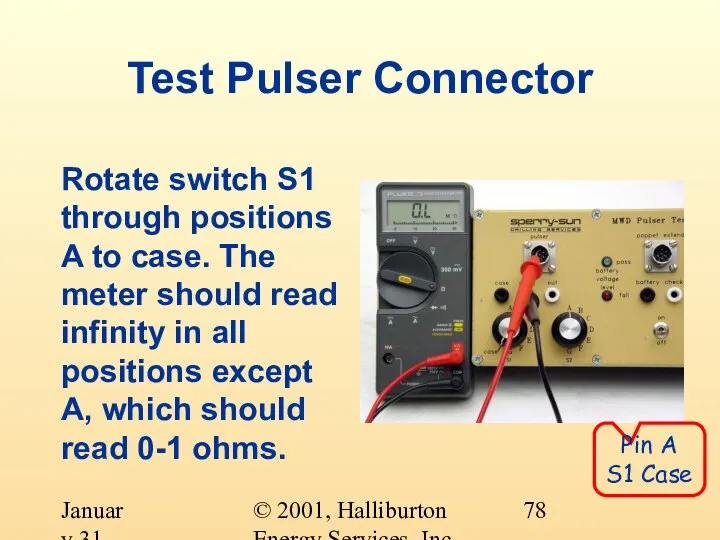
- 78. © 2001, Halliburton Energy Services, Inc. January 31, 2001 Test Pulser Connector Rotate switch S1 through
- 79. © 2001, Halliburton Energy Services, Inc. January 31, 2001 Test Pulser Connector Repeat this for pins
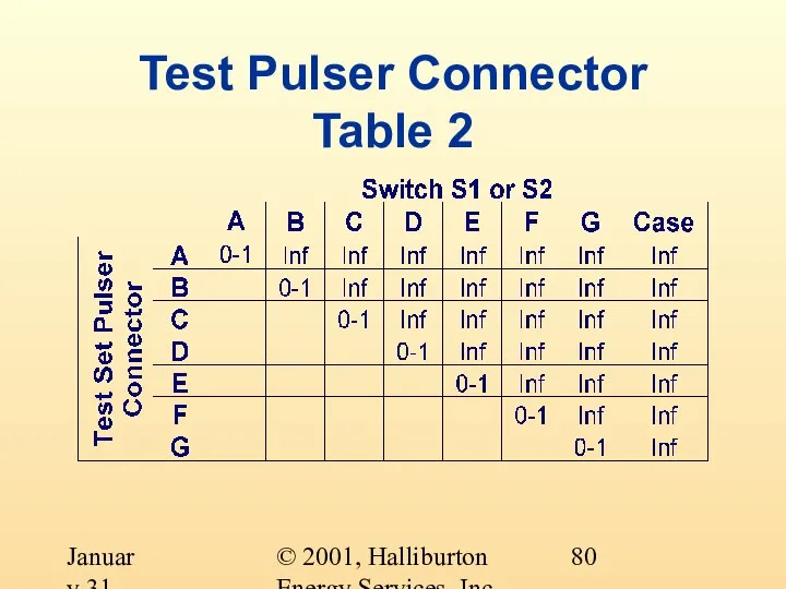
- 80. © 2001, Halliburton Energy Services, Inc. January 31, 2001 Test Pulser Connector Table 2
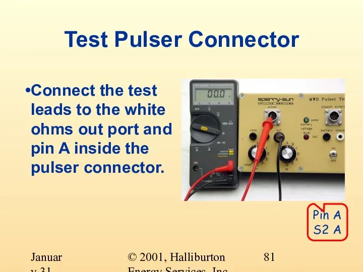
- 81. © 2001, Halliburton Energy Services, Inc. January 31, 2001 Test Pulser Connector Connect the test leads
- 82. © 2001, Halliburton Energy Services, Inc. January 31, 2001 Test Pulser Connector Rotate switch S2 through
- 83. © 2001, Halliburton Energy Services, Inc. January 31, 2001 Test Pulser Connector Repeat this for pins
- 84. © 2001, Halliburton Energy Services, Inc. January 31, 2001 Test Poppet Extend Connector Ensure that the
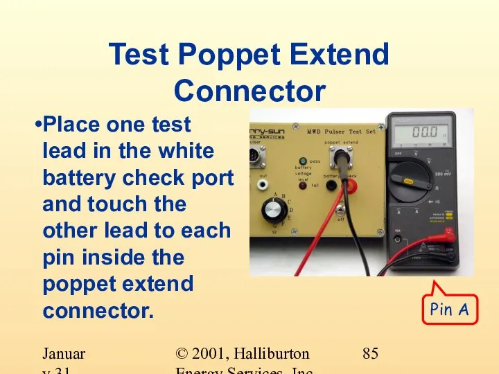
- 85. © 2001, Halliburton Energy Services, Inc. January 31, 2001 Test Poppet Extend Connector Place one test
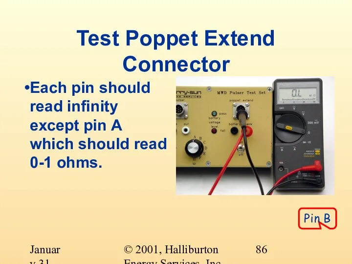
- 86. © 2001, Halliburton Energy Services, Inc. January 31, 2001 Test Poppet Extend Connector Each pin should
- 87. © 2001, Halliburton Energy Services, Inc. January 31, 2001 Test Poppet Extend Connector Remove the test
- 88. © 2001, Halliburton Energy Services, Inc. January 31, 2001 Test Poppet Extend Connector Pin A
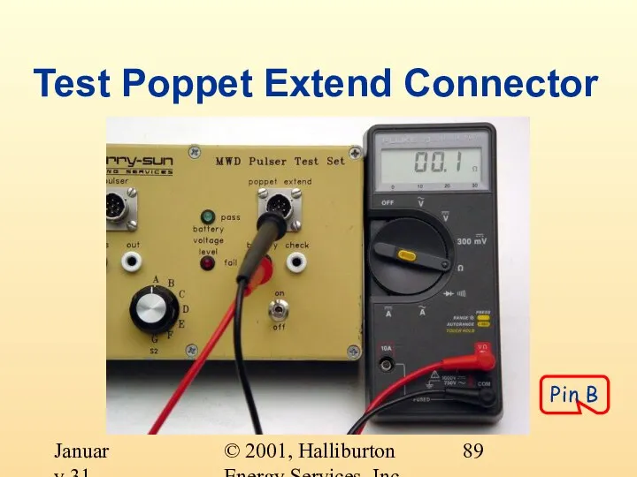
- 89. © 2001, Halliburton Energy Services, Inc. January 31, 2001 Test Poppet Extend Connector Pin B
- 90. © 2001, Halliburton Energy Services, Inc. January 31, 2001 Test Poppet Extend Connector Each pin should
- 91. © 2001, Halliburton Energy Services, Inc. January 31, 2001 Test Internal Batteries Set the meter to
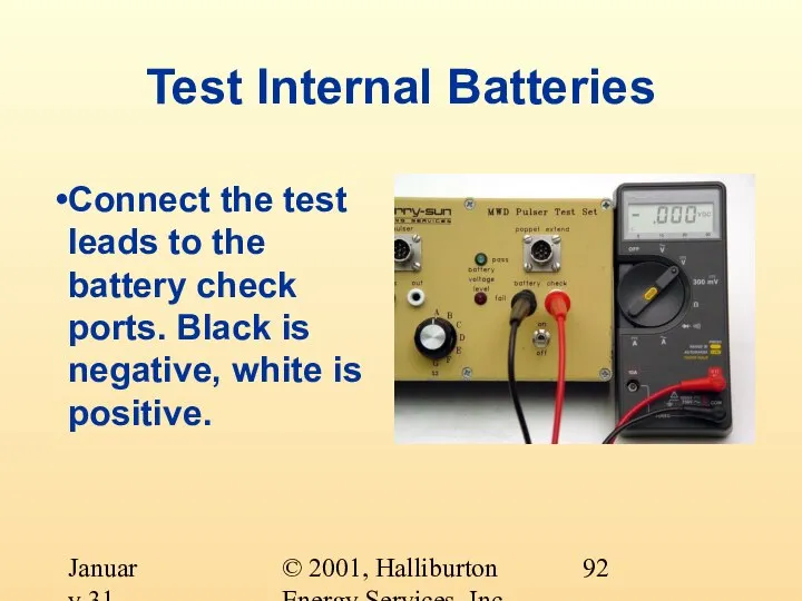
- 92. © 2001, Halliburton Energy Services, Inc. January 31, 2001 Test Internal Batteries Connect the test leads
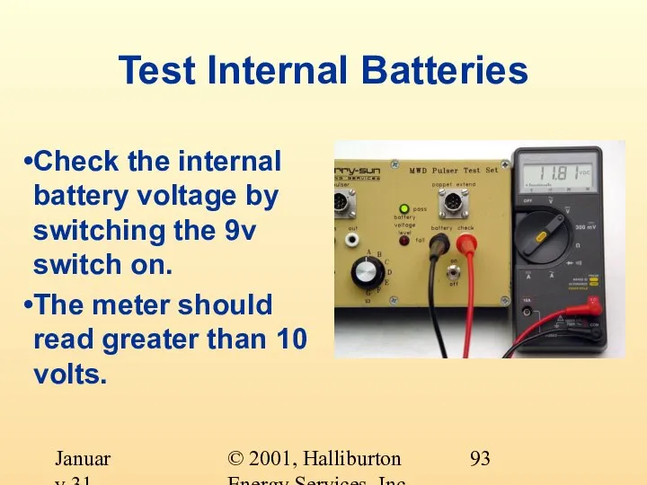
- 93. © 2001, Halliburton Energy Services, Inc. January 31, 2001 Test Internal Batteries Check the internal battery
- 94. © 2001, Halliburton Energy Services, Inc. January 31, 2001 Test Internal Batteries Turn the 9v switch
- 95. © 2001, Halliburton Energy Services, Inc. January 31, 2001 Replace Internal Batteries If the voltage is
- 97. Скачать презентацию
Слайд 2© 2001, Halliburton Energy Services, Inc.
January 31, 2001
Pulser Testing Objectives
At the completion
© 2001, Halliburton Energy Services, Inc.
January 31, 2001
Pulser Testing Objectives
At the completion
Слайд 3© 2001, Halliburton Energy Services, Inc.
January 31, 2001
The Pulser
The central component of
© 2001, Halliburton Energy Services, Inc.
January 31, 2001
The Pulser
The central component of
Слайд 4© 2001, Halliburton Energy Services, Inc.
January 31, 2001
The Pulser
Generates electrical and hydraulic
© 2001, Halliburton Energy Services, Inc.
January 31, 2001
The Pulser
Generates electrical and hydraulic
Слайд 5© 2001, Halliburton Energy Services, Inc.
January 31, 2001
Pulser’s Hydraulic Power
Operates a poppet/orifice
© 2001, Halliburton Energy Services, Inc.
January 31, 2001
Pulser’s Hydraulic Power
Operates a poppet/orifice
Слайд 6© 2001, Halliburton Energy Services, Inc.
January 31, 2001
Pulser’s
Hydraulic
System
Control Valve
Main Valve
Pump
Piston
Valve
Bypass Port
Piston
Bypass
© 2001, Halliburton Energy Services, Inc.
January 31, 2001
Pulser’s
Hydraulic
System
Control Valve
Main Valve
Pump
Piston
Valve
Bypass Port
Piston
Bypass
Слайд 7© 2001, Halliburton Energy Services, Inc.
January 31, 2001
Pulser’s
Hydraulic System
Control valve open
Flow
© 2001, Halliburton Energy Services, Inc.
January 31, 2001
Pulser’s
Hydraulic System
Control valve open
Flow
Слайд 8© 2001, Halliburton Energy Services, Inc.
January 31, 2001
Pulser’s
Hydraulic System
Control valve closed
No
© 2001, Halliburton Energy Services, Inc.
January 31, 2001
Pulser’s
Hydraulic System
Control valve closed
No
Слайд 9© 2001, Halliburton Energy Services, Inc.
January 31, 2001
Pulser’s
Hydraulic System
Control valve closed
No
© 2001, Halliburton Energy Services, Inc.
January 31, 2001
Pulser’s
Hydraulic System
Control valve closed
No
Слайд 10© 2001, Halliburton Energy Services, Inc.
January 31, 2001
Pulser’s
Hydraulic
System
© 2001, Halliburton Energy Services, Inc.
January 31, 2001
Pulser’s
Hydraulic
System
Слайд 11© 2001, Halliburton Energy Services, Inc.
January 31, 2001
Pulser’s Hydraulic System
The control valve
© 2001, Halliburton Energy Services, Inc.
January 31, 2001
Pulser’s Hydraulic System
The control valve
Слайд 12© 2001, Halliburton Energy Services, Inc.
January 31, 2001
Pulser’s Electrical Power
Generator consists of
© 2001, Halliburton Energy Services, Inc.
January 31, 2001
Pulser’s Electrical Power
Generator consists of
Слайд 13© 2001, Halliburton Energy Services, Inc.
January 31, 2001
The Parts of a Pulser
2
© 2001, Halliburton Energy Services, Inc.
January 31, 2001
The Parts of a Pulser
2
Слайд 14© 2001, Halliburton Energy Services, Inc.
January 31, 2001
Boot
Booted Vs. Bootless Pulser
Bootless
© 2001, Halliburton Energy Services, Inc.
January 31, 2001
Boot
Booted Vs. Bootless Pulser
Bootless
Слайд 15© 2001, Halliburton Energy Services, Inc.
January 31, 2001
Booted Vs. Bootless Pulser
Boot
Gas permeable
Susceptible
© 2001, Halliburton Energy Services, Inc.
January 31, 2001
Booted Vs. Bootless Pulser
Boot
Gas permeable
Susceptible
Слайд 16© 2001, Halliburton Energy Services, Inc.
January 31, 2001
Booted Vs. Bootless Pulser
Bootless
Increased reliability
Requires
© 2001, Halliburton Energy Services, Inc.
January 31, 2001
Booted Vs. Bootless Pulser
Bootless
Increased reliability
Requires
Слайд 17© 2001, Halliburton Energy Services, Inc.
January 31, 2001
Pulser Connections
7-pin Amphenol
Connector
4 Cond. Rotational
Connector
© 2001, Halliburton Energy Services, Inc.
January 31, 2001
Pulser Connections
7-pin Amphenol
Connector
4 Cond. Rotational
Connector
Слайд 18© 2001, Halliburton Energy Services, Inc.
January 31, 2001
Pulser Connection
7-pin Amphenol
Used for DWD
Careful
© 2001, Halliburton Energy Services, Inc.
January 31, 2001
Pulser Connection
7-pin Amphenol
Used for DWD
Careful
Слайд 19© 2001, Halliburton Energy Services, Inc.
January 31, 2001
Pulser Connection
4-Conductor Rotational Connector
Used for
© 2001, Halliburton Energy Services, Inc.
January 31, 2001
Pulser Connection
4-Conductor Rotational Connector
Used for
Слайд 20© 2001, Halliburton Energy Services, Inc.
January 31, 2001
The Four Current Pulsers
Mark 6
© 2001, Halliburton Energy Services, Inc.
January 31, 2001
The Four Current Pulsers
Mark 6
Слайд 21© 2001, Halliburton Energy Services, Inc.
January 31, 2001
Mark 6 DWD
7-Pin Amphenol Connector
Maximum
© 2001, Halliburton Energy Services, Inc.
January 31, 2001
Mark 6 DWD
7-Pin Amphenol Connector
Maximum

Слайд 22© 2001, Halliburton Energy Services, Inc.
January 31, 2001
Mark 7 Solar
4-Conductor Rotational Connector
Maximum
© 2001, Halliburton Energy Services, Inc.
January 31, 2001
Mark 7 Solar
4-Conductor Rotational Connector
Maximum

Слайд 23© 2001, Halliburton Energy Services, Inc.
January 31, 2001
Mark 8 Solar
4-Conductor Rotational Connector
Maximum
© 2001, Halliburton Energy Services, Inc.
January 31, 2001
Mark 8 Solar
4-Conductor Rotational Connector
Maximum
Слайд 24© 2001, Halliburton Energy Services, Inc.
January 31, 2001
Mark 8 DWD
7-Pin Amphenol Connector
Maximum
© 2001, Halliburton Energy Services, Inc.
January 31, 2001
Mark 8 DWD
7-Pin Amphenol Connector
Maximum
Слайд 25© 2001, Halliburton Energy Services, Inc.
January 31, 2001
How to Identify Pulsers
Mark 6
© 2001, Halliburton Energy Services, Inc.
January 31, 2001
How to Identify Pulsers
Mark 6
Слайд 26© 2001, Halliburton Energy Services, Inc.
January 31, 2001
How to Identify Pulsers
Lower Filling
© 2001, Halliburton Energy Services, Inc.
January 31, 2001
How to Identify Pulsers
Lower Filling
Слайд 27© 2001, Halliburton Energy Services, Inc.
January 31, 2001
How to Identify Pulsers
Mark 8
© 2001, Halliburton Energy Services, Inc.
January 31, 2001
How to Identify Pulsers
Mark 8
Слайд 28© 2001, Halliburton Energy Services, Inc.
January 31, 2001
Testing the Pulser
Two tests
Resistance
Tests electrical
© 2001, Halliburton Energy Services, Inc.
January 31, 2001
Testing the Pulser
Two tests
Resistance
Tests electrical
Слайд 29© 2001, Halliburton Energy Services, Inc.
January 31, 2001
Pulser Test Equipment
DWD Electronic Test
© 2001, Halliburton Energy Services, Inc.
January 31, 2001
Pulser Test Equipment
DWD Electronic Test
Слайд 30© 2001, Halliburton Energy Services, Inc.
January 31, 2001
Additional Test Equipment for Solar
© 2001, Halliburton Energy Services, Inc.
January 31, 2001
Additional Test Equipment for Solar
Слайд 31© 2001, Halliburton Energy Services, Inc.
January 31, 2001
MWD Pulser Test Set
9V Switch
© 2001, Halliburton Energy Services, Inc.
January 31, 2001
MWD Pulser Test Set
9V Switch
Слайд 32© 2001, Halliburton Energy Services, Inc.
January 31, 2001
Digital Multi-meter
© 2001, Halliburton Energy Services, Inc.
January 31, 2001
Digital Multi-meter
Слайд 33© 2001, Halliburton Energy Services, Inc.
January 31, 2001
Coil Cord
7-Pin Female
Amphenol Connector
7-Pin
© 2001, Halliburton Energy Services, Inc.
January 31, 2001
Coil Cord
7-Pin Female
Amphenol Connector
7-Pin
Слайд 34© 2001, Halliburton Energy Services, Inc.
January 31, 2001
Coil Cord
A
B
C
D
E
F
G
A
B
C
D
E
F
G
Probe
Pulser
© 2001, Halliburton Energy Services, Inc.
January 31, 2001
Coil Cord
A
B
C
D
E
F
G
A
B
C
D
E
F
G
Probe
Pulser
Слайд 35© 2001, Halliburton Energy Services, Inc.
January 31, 2001
Pulser Resistance Test Equipment
Pulser Ground
© 2001, Halliburton Energy Services, Inc.
January 31, 2001
Pulser Resistance Test Equipment
Pulser Ground
Слайд 36© 2001, Halliburton Energy Services, Inc.
January 31, 2001
Pulser Extension Test Equipment
Poppet retraction
© 2001, Halliburton Energy Services, Inc.
January 31, 2001
Pulser Extension Test Equipment
Poppet retraction
Слайд 37© 2001, Halliburton Energy Services, Inc.
January 31, 2001
Pulser Resistance Test Equipment
Solar 175
© 2001, Halliburton Energy Services, Inc.
January 31, 2001
Pulser Resistance Test Equipment
Solar 175
Слайд 38© 2001, Halliburton Energy Services, Inc.
January 31, 2001
Pulser Resistance Test Purpose
Tests the
© 2001, Halliburton Energy Services, Inc.
January 31, 2001
Pulser Resistance Test Purpose
Tests the
Слайд 39© 2001, Halliburton Energy Services, Inc.
January 31, 2001
Pulser Resistance Test Procedure
Set the
© 2001, Halliburton Energy Services, Inc.
January 31, 2001
Pulser Resistance Test Procedure
Set the
Слайд 40© 2001, Halliburton Energy Services, Inc.
January 31, 2001
Pulser Case Lead Continuity
Measure the
© 2001, Halliburton Energy Services, Inc.
January 31, 2001
Pulser Case Lead Continuity
Measure the
Слайд 41© 2001, Halliburton Energy Services, Inc.
January 31, 2001
Pulser Resistance Test Procedure
Connect
© 2001, Halliburton Energy Services, Inc.
January 31, 2001
Pulser Resistance Test Procedure
Connect
Слайд 42© 2001, Halliburton Energy Services, Inc.
January 31, 2001
Pulser Resistance Test Procedure
Connect the
© 2001, Halliburton Energy Services, Inc.
January 31, 2001
Pulser Resistance Test Procedure
Connect the
Слайд 43© 2001, Halliburton Energy Services, Inc.
January 31, 2001
Pulser Resistance Test Procedure
Connect
© 2001, Halliburton Energy Services, Inc.
January 31, 2001
Pulser Resistance Test Procedure
Connect
Слайд 44© 2001, Halliburton Energy Services, Inc.
January 31, 2001
Pulser Resistance Test Procedure
Check
© 2001, Halliburton Energy Services, Inc.
January 31, 2001
Pulser Resistance Test Procedure
Check
Слайд 45© 2001, Halliburton Energy Services, Inc.
January 31, 2001
DWD Pulser Resistances
© 2001, Halliburton Energy Services, Inc.
January 31, 2001
DWD Pulser Resistances
Слайд 46© 2001, Halliburton Energy Services, Inc.
January 31, 2001
Solar Pulser Resistances
© 2001, Halliburton Energy Services, Inc.
January 31, 2001
Solar Pulser Resistances
Слайд 47© 2001, Halliburton Energy Services, Inc.
January 31, 2001
Pulser Resistance Test Procedure
A
© 2001, Halliburton Energy Services, Inc.
January 31, 2001
Pulser Resistance Test Procedure
A
Слайд 48© 2001, Halliburton Energy Services, Inc.
January 31, 2001
Pulser Resistance Test Procedure
If any
© 2001, Halliburton Energy Services, Inc.
January 31, 2001
Pulser Resistance Test Procedure
If any
Слайд 49© 2001, Halliburton Energy Services, Inc.
January 31, 2001
Pulser Resistance Test Procedure
What was
© 2001, Halliburton Energy Services, Inc.
January 31, 2001
Pulser Resistance Test Procedure
What was
Слайд 50© 2001, Halliburton Energy Services, Inc.
January 31, 2001
Pulser Extension/Retraction Test Purpose
Basic test
© 2001, Halliburton Energy Services, Inc.
January 31, 2001
Pulser Extension/Retraction Test Purpose
Basic test
Слайд 51© 2001, Halliburton Energy Services, Inc.
January 31, 2001
Pulser Extension/Retraction Test Procedure
Clean the
© 2001, Halliburton Energy Services, Inc.
January 31, 2001
Pulser Extension/Retraction Test Procedure
Clean the
Слайд 52© 2001, Halliburton Energy Services, Inc.
January 31, 2001
Pulser Extension/Retraction Test Procedure
Install an
© 2001, Halliburton Energy Services, Inc.
January 31, 2001
Pulser Extension/Retraction Test Procedure
Install an
Слайд 53© 2001, Halliburton Energy Services, Inc.
January 31, 2001
Pulser Extension/Retraction Test Procedure
Prepare the
© 2001, Halliburton Energy Services, Inc.
January 31, 2001
Pulser Extension/Retraction Test Procedure
Prepare the
Слайд 54© 2001, Halliburton Energy Services, Inc.
January 31, 2001
Pulser Extension/Retraction Test Procedure
Slide the
© 2001, Halliburton Energy Services, Inc.
January 31, 2001
Pulser Extension/Retraction Test Procedure
Slide the
Слайд 55© 2001, Halliburton Energy Services, Inc.
January 31, 2001
Pulser Extension/Retraction Test Procedure
Insert the
© 2001, Halliburton Energy Services, Inc.
January 31, 2001
Pulser Extension/Retraction Test Procedure
Insert the
Слайд 56© 2001, Halliburton Energy Services, Inc.
January 31, 2001
Pulser Extension/Retraction Test Procedure
Screw the
© 2001, Halliburton Energy Services, Inc.
January 31, 2001
Pulser Extension/Retraction Test Procedure
Screw the
Слайд 57© 2001, Halliburton Energy Services, Inc.
January 31, 2001
Pulser Extension/Retraction Test Procedure
Connect the
© 2001, Halliburton Energy Services, Inc.
January 31, 2001
Pulser Extension/Retraction Test Procedure
Connect the
Слайд 58© 2001, Halliburton Energy Services, Inc.
January 31, 2001
Pulser Extension/Retraction Test Procedure
Rotate the
© 2001, Halliburton Energy Services, Inc.
January 31, 2001
Pulser Extension/Retraction Test Procedure
Rotate the
Слайд 59© 2001, Halliburton Energy Services, Inc.
January 31, 2001
Pulser Extension/Retraction Test Procedure
Monitor the
© 2001, Halliburton Energy Services, Inc.
January 31, 2001
Pulser Extension/Retraction Test Procedure
Monitor the
Слайд 60© 2001, Halliburton Energy Services, Inc.
January 31, 2001
Pulser Extension/Retraction Test Procedure
Rotate the
© 2001, Halliburton Energy Services, Inc.
January 31, 2001
Pulser Extension/Retraction Test Procedure
Rotate the
Слайд 61© 2001, Halliburton Energy Services, Inc.
January 31, 2001
Pulser Extension/Retraction Test Procedure
Turn off
© 2001, Halliburton Energy Services, Inc.
January 31, 2001
Pulser Extension/Retraction Test Procedure
Turn off
Слайд 62© 2001, Halliburton Energy Services, Inc.
January 31, 2001
Pulser Extension/Retraction Test Procedure
Monitor retraction
For
© 2001, Halliburton Energy Services, Inc.
January 31, 2001
Pulser Extension/Retraction Test Procedure
Monitor retraction
For
Слайд 63© 2001, Halliburton Energy Services, Inc.
January 31, 2001
Pulser Extension/Retraction Test Procedure
Record the
© 2001, Halliburton Energy Services, Inc.
January 31, 2001
Pulser Extension/Retraction Test Procedure
Record the
Слайд 64© 2001, Halliburton Energy Services, Inc.
January 31, 2001
Pulser Extension/Retraction Test Procedure
Should the
© 2001, Halliburton Energy Services, Inc.
January 31, 2001
Pulser Extension/Retraction Test Procedure
Should the
Слайд 65© 2001, Halliburton Energy Services, Inc.
January 31, 2001
Pulser Extension/Retraction Test Procedure
What was
© 2001, Halliburton Energy Services, Inc.
January 31, 2001
Pulser Extension/Retraction Test Procedure
What was
Слайд 66© 2001, Halliburton Energy Services, Inc.
January 31, 2001
Testing an MWD Pulser Test
© 2001, Halliburton Energy Services, Inc.
January 31, 2001
Testing an MWD Pulser Test
Слайд 67© 2001, Halliburton Energy Services, Inc.
January 31, 2001
Test S1 and S2 Switches
Set
© 2001, Halliburton Energy Services, Inc.
January 31, 2001
Test S1 and S2 Switches
Set
Слайд 68© 2001, Halliburton Energy Services, Inc.
January 31, 2001
Test S1 and S2 Switches
Check
© 2001, Halliburton Energy Services, Inc.
January 31, 2001
Test S1 and S2 Switches
Check
Слайд 69© 2001, Halliburton Energy Services, Inc.
January 31, 2001
Test S1 and S2 Switches
Table
© 2001, Halliburton Energy Services, Inc.
January 31, 2001
Test S1 and S2 Switches Table
Слайд 70© 2001, Halliburton Energy Services, Inc.
January 31, 2001
Test S1 and S2 Switches
A
© 2001, Halliburton Energy Services, Inc.
January 31, 2001
Test S1 and S2 Switches
A
Слайд 71© 2001, Halliburton Energy Services, Inc.
January 31, 2001
Test S1 and S2 Switches
G
© 2001, Halliburton Energy Services, Inc.
January 31, 2001
Test S1 and S2 Switches
G
Слайд 72© 2001, Halliburton Energy Services, Inc.
January 31, 2001
Test Ohms Out & Case
© 2001, Halliburton Energy Services, Inc.
January 31, 2001
Test Ohms Out & Case
Слайд 73© 2001, Halliburton Energy Services, Inc.
January 31, 2001
Test Ohms Out & Case
© 2001, Halliburton Energy Services, Inc.
January 31, 2001
Test Ohms Out & Case
Слайд 74© 2001, Halliburton Energy Services, Inc.
January 31, 2001
Test Ohms Out & Case
© 2001, Halliburton Energy Services, Inc.
January 31, 2001
Test Ohms Out & Case
Слайд 75© 2001, Halliburton Energy Services, Inc.
January 31, 2001
Test Ohms Out & Case
© 2001, Halliburton Energy Services, Inc.
January 31, 2001
Test Ohms Out & Case

Слайд 76© 2001, Halliburton Energy Services, Inc.
January 31, 2001
Test Ohms Out & Case
© 2001, Halliburton Energy Services, Inc.
January 31, 2001
Test Ohms Out & Case
Слайд 77© 2001, Halliburton Energy Services, Inc.
January 31, 2001
Test Pulser Connector
Connect the test
© 2001, Halliburton Energy Services, Inc.
January 31, 2001
Test Pulser Connector
Connect the test
Слайд 78© 2001, Halliburton Energy Services, Inc.
January 31, 2001
Test Pulser Connector
Rotate switch S1
© 2001, Halliburton Energy Services, Inc.
January 31, 2001
Test Pulser Connector
Rotate switch S1
Слайд 79© 2001, Halliburton Energy Services, Inc.
January 31, 2001
Test Pulser Connector
Repeat this for
© 2001, Halliburton Energy Services, Inc.
January 31, 2001
Test Pulser Connector
Repeat this for
Слайд 80© 2001, Halliburton Energy Services, Inc.
January 31, 2001
Test Pulser Connector
Table 2
© 2001, Halliburton Energy Services, Inc.
January 31, 2001
Test Pulser Connector
Table 2
Слайд 81© 2001, Halliburton Energy Services, Inc.
January 31, 2001
Test Pulser Connector
Connect the test
© 2001, Halliburton Energy Services, Inc.
January 31, 2001
Test Pulser Connector
Connect the test
Слайд 82© 2001, Halliburton Energy Services, Inc.
January 31, 2001
Test Pulser Connector
Rotate switch S2
© 2001, Halliburton Energy Services, Inc.
January 31, 2001
Test Pulser Connector
Rotate switch S2
Слайд 83© 2001, Halliburton Energy Services, Inc.
January 31, 2001
Test Pulser Connector
Repeat this for
© 2001, Halliburton Energy Services, Inc.
January 31, 2001
Test Pulser Connector
Repeat this for
Слайд 84© 2001, Halliburton Energy Services, Inc.
January 31, 2001
Test Poppet Extend Connector
Ensure that
© 2001, Halliburton Energy Services, Inc.
January 31, 2001
Test Poppet Extend Connector
Ensure that
Слайд 85© 2001, Halliburton Energy Services, Inc.
January 31, 2001
Test Poppet Extend Connector
Place
© 2001, Halliburton Energy Services, Inc.
January 31, 2001
Test Poppet Extend Connector
Place
Слайд 86© 2001, Halliburton Energy Services, Inc.
January 31, 2001
Test Poppet Extend Connector
Each pin
© 2001, Halliburton Energy Services, Inc.
January 31, 2001
Test Poppet Extend Connector
Each pin
Слайд 87© 2001, Halliburton Energy Services, Inc.
January 31, 2001
Test Poppet Extend Connector
Remove the
© 2001, Halliburton Energy Services, Inc.
January 31, 2001
Test Poppet Extend Connector
Remove the
Слайд 88© 2001, Halliburton Energy Services, Inc.
January 31, 2001
Test Poppet Extend Connector
Pin
© 2001, Halliburton Energy Services, Inc.
January 31, 2001
Test Poppet Extend Connector
Pin

Слайд 89© 2001, Halliburton Energy Services, Inc.
January 31, 2001
Test Poppet Extend Connector
Pin
© 2001, Halliburton Energy Services, Inc.
January 31, 2001
Test Poppet Extend Connector
Pin
Слайд 90© 2001, Halliburton Energy Services, Inc.
January 31, 2001
Test Poppet Extend Connector
Each
© 2001, Halliburton Energy Services, Inc.
January 31, 2001
Test Poppet Extend Connector
Each
Слайд 91© 2001, Halliburton Energy Services, Inc.
January 31, 2001
Test Internal Batteries
Set the meter
© 2001, Halliburton Energy Services, Inc.
January 31, 2001
Test Internal Batteries
Set the meter
Слайд 92© 2001, Halliburton Energy Services, Inc.
January 31, 2001
Test Internal Batteries
Connect the test
© 2001, Halliburton Energy Services, Inc.
January 31, 2001
Test Internal Batteries
Connect the test
Слайд 93© 2001, Halliburton Energy Services, Inc.
January 31, 2001
Test Internal Batteries
Check the internal
© 2001, Halliburton Energy Services, Inc.
January 31, 2001
Test Internal Batteries
Check the internal
Слайд 94© 2001, Halliburton Energy Services, Inc.
January 31, 2001
Test Internal Batteries
Turn the 9v
© 2001, Halliburton Energy Services, Inc.
January 31, 2001
Test Internal Batteries
Turn the 9v
Слайд 95© 2001, Halliburton Energy Services, Inc.
January 31, 2001
Replace Internal Batteries
If the voltage
© 2001, Halliburton Energy Services, Inc.
January 31, 2001
Replace Internal Batteries
If the voltage
 Силовое многоборье на гимнастической перекладине Русский силомер
 Учёба и здоровье
 Norms and the Network
 Джим Кэрри
 Презентация на тему Проектный метод - как метод развивающего обучения дошкольников
 Команда Адреналин МБОУ СОШ №50 г.Барнаула
 Решение нелинейных уравнений
 Презентация на тему Предлоги: в, на, под, за
 День народного единства и согласия
 Презентация на тему Л.Н. Толстой "После бала"
  739365 (1)
 Презентация на тему Иван Андреевич Крылов Басни
  Серия представлена тремя продуктами: Лидер 21 века Тайм-менеджмент. Наука успевать НЛП. Стратегия успеха
 Проект «Школа Росатома» для 22 городов Реализация национальной образовательной инициативы «Наша новая школа» в городах располож
 Счастливы те люди. Кто учит Библию.
 Диффузия
 Акция Service Clinic
 Диагностика и мониторинг обученности учащихся в рамках достижения планируемых результатов обучения
 Как связаны земля и небо?
 Unique Museums of Karelia Карельский Институт Туризма
  Депрессия в пожилом возрасте
 Свет родных берёз
 Внутриквартальная спортивно-игровая площадка с организацией ночной автостоянки
 Презентация на тему Passive voice
 Викторина
 Обеспечение современного качества общего образования в сельской малокомплектной школе путем реализации проекта «Учительский до
 Освещение жилого дома
 Загадки трудных слов