- Composite Materials

Содержание
- 2. Introduction A Composite material is a material system composed of two or more macro constituents that
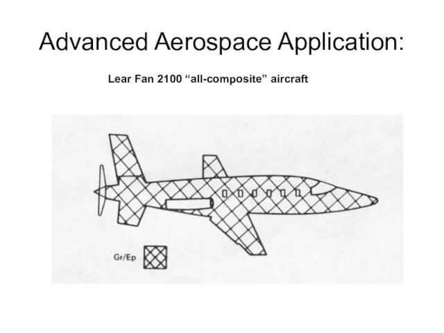
- 3. Advanced Aerospace Application: Lear Fan 2100 “all-composite” aircraft
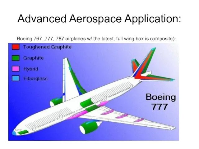
- 4. Advanced Aerospace Application: Boeing 767 ,777, 787 airplanes w/ the latest, full wing box is composite):
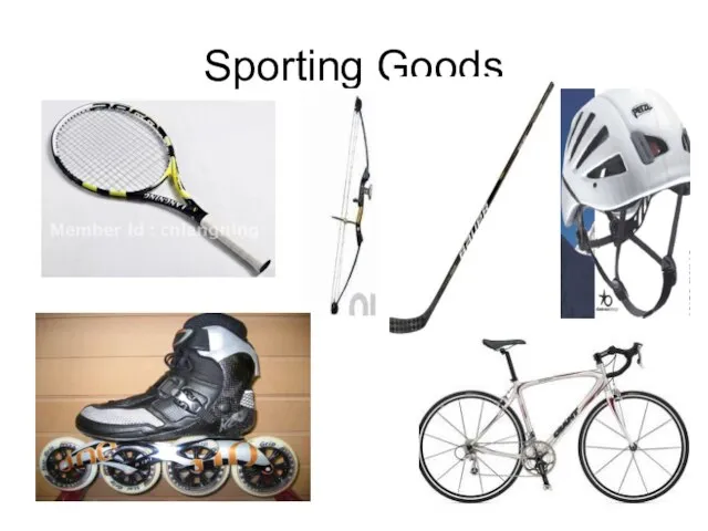
- 5. Sporting Goods
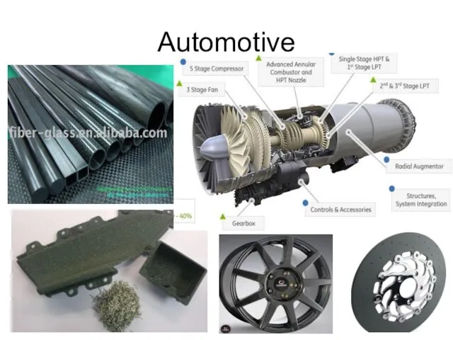
- 6. Automotive
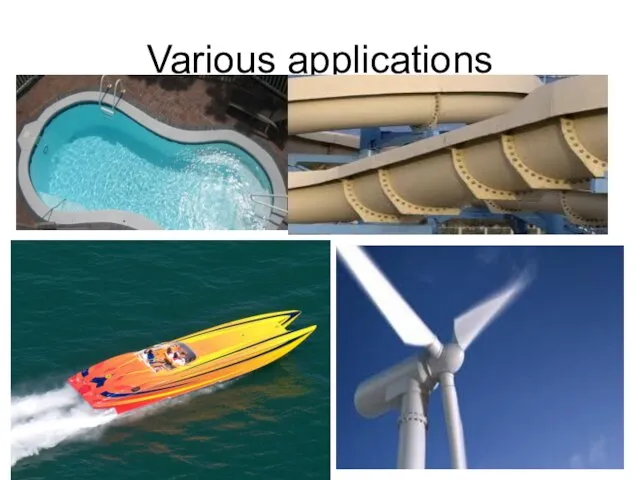
- 7. Various applications
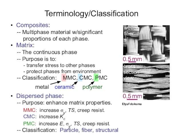
- 8. • Composites: -- Multiphase material w/significant proportions of each phase. • Dispersed phase: -- Purpose: enhance
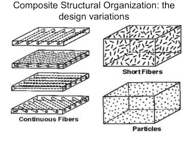
- 9. Composite Structural Organization: the design variations
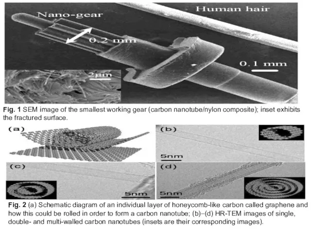
- 10. Fig. 2 (a) Schematic diagram of an individual layer of honeycomb-like carbon called graphene and how
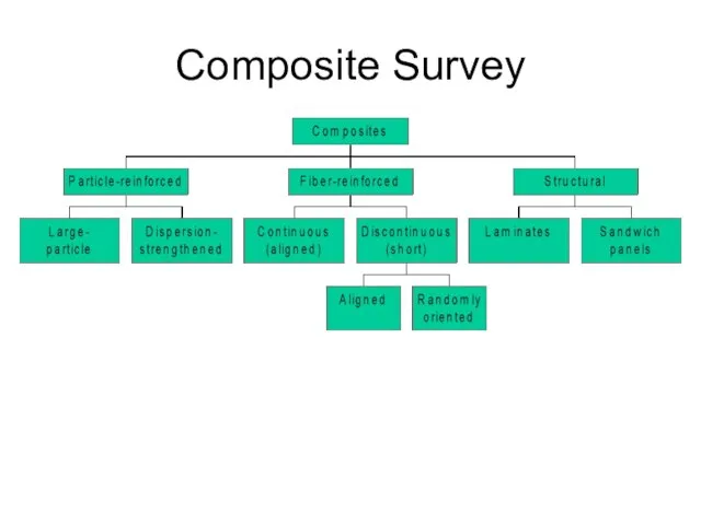
- 11. Composite Survey
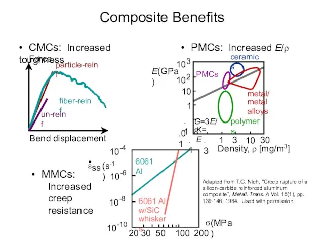
- 12. • CMCs: Increased toughness Composite Benefits
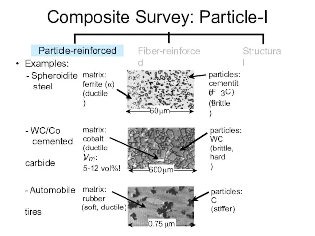
- 13. Composite Survey: Particle-I
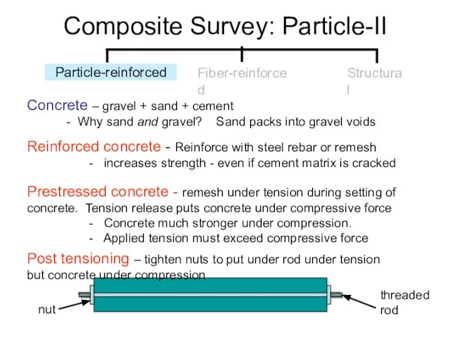
- 14. Composite Survey: Particle-II Concrete – gravel + sand + cement - Why sand and gravel? Sand
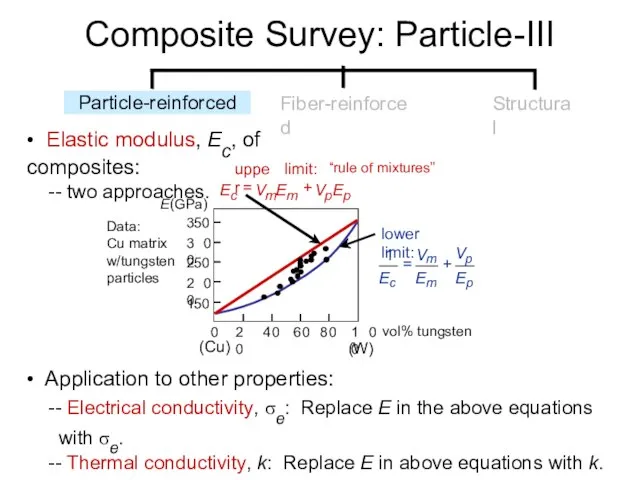
- 15. • Elastic modulus, Ec, of composites: -- two approaches. • Application to other properties: -- Electrical
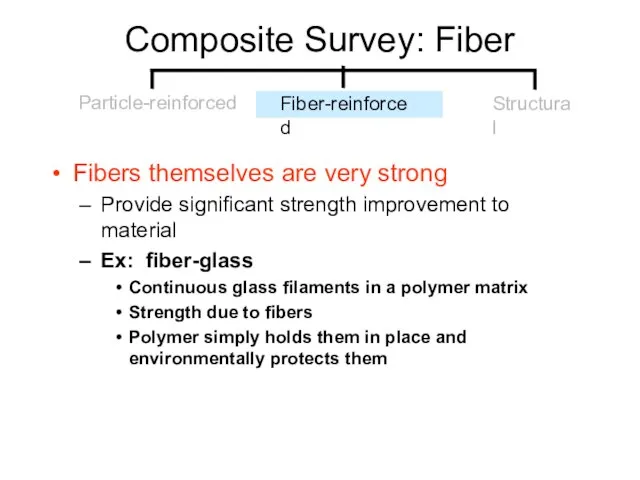
- 16. Composite Survey: Fiber Fibers themselves are very strong Provide significant strength improvement to material Ex: fiber-glass
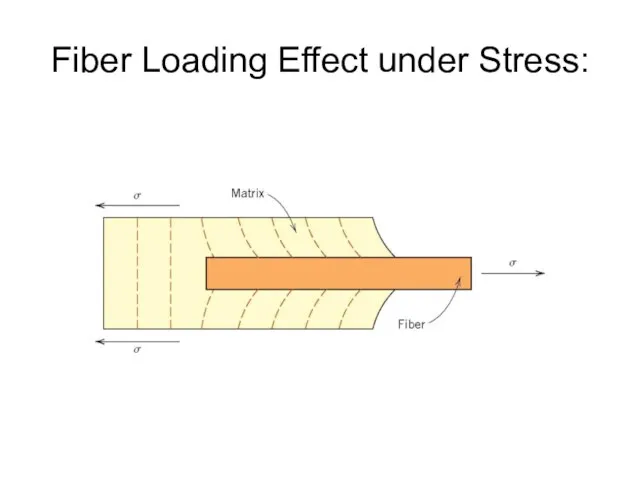
- 17. Fiber Loading Effect under Stress:
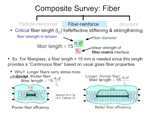
- 18. • Critical fiber length (lC) for effective stiffening & strengthening: • Ex: For fiberglass, a fiber
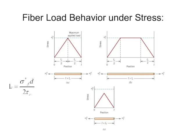
- 19. Fiber Load Behavior under Stress:
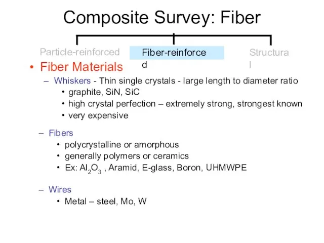
- 20. Composite Survey: Fiber Fiber Materials Whiskers - Thin single crystals - large length to diameter ratio
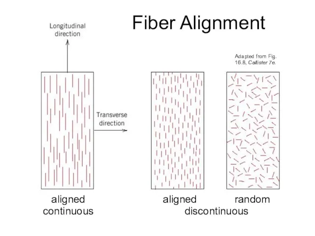
- 21. Fiber Alignment aligned continuous aligned random discontinuous Adapted from Fig. 16.8, Callister 7e.
- 22. Behavior under load for Fibers & Matrix
- 23. Composite Strength: Longitudinal Loading Continuous fibers - Estimate fiber-reinforced composite strength for long continuous fibers in
- 24. Composite Strength: Transverse Loading In transverse loading the fibers carry less of the load and are
- 25. An Example: Note: (for ease of conversion) 6870 N/m2 per psi! UTS, SI Modulus, SI 57.9
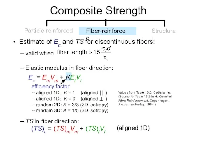
- 26. • Estimate of Ec and TS for discontinuous fibers: -- valid when -- Elastic modulus in
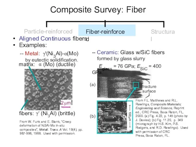
- 27. • Aligned Continuous fibers • Examples: From W. Funk and E. Blank, “Creep deformation of Ni3Al-Mo
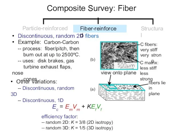
- 28. • Discontinuous, random 2D fibers • Example: Carbon-Carbon -- process: fiber/pitch, then burn out at up
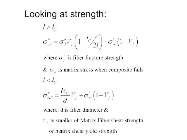
- 29. Looking at strength:
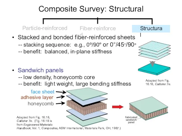
- 30. • Stacked and bonded fiber-reinforced sheets -- stacking sequence: e.g., 0º/90º or 0°/45°/90º -- benefit: balanced,
- 31. Composite Manufacturing Processes Particulate Methods: Sintering Fiber reinforced: Several Structural: Usually Hand lay-up and atmospheric curing
- 33. Open Mold Processes Only one mold (male or female) is needed and may be made of
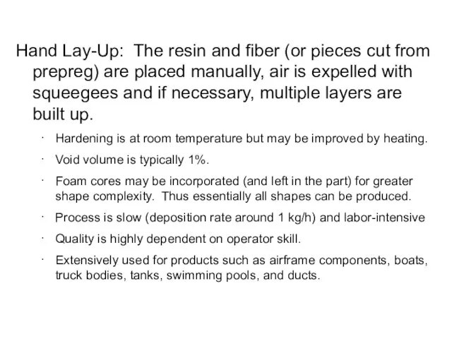
- 34. Hand Lay-Up: The resin and fiber (or pieces cut from prepreg) are placed manually, air is
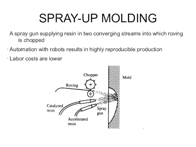
- 35. A spray gun supplying resin in two converging streams into which roving is chopped Automation with
- 36. Cut and lay the ply or prepreg under computer control and without tension; may allow reentrant
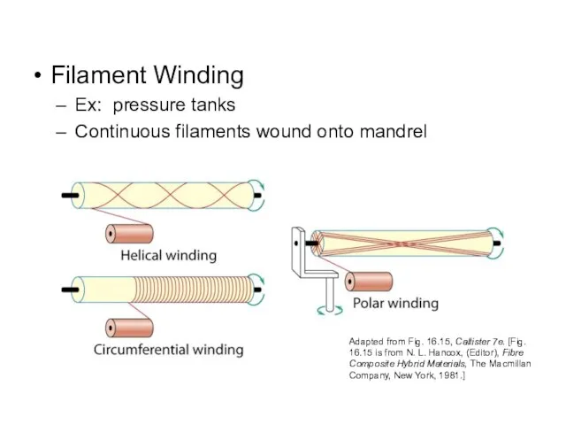
- 37. Filament Winding Ex: pressure tanks Continuous filaments wound onto mandrel Adapted from Fig. 16.15, Callister 7e.
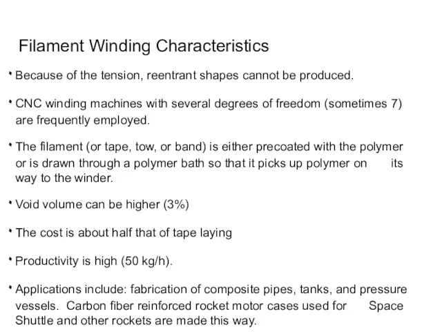
- 38. Filament Winding Characteristics Because of the tension, reentrant shapes cannot be produced. CNC winding machines with
- 39. Pultrusion Fibers are impregnate with a prepolymer, exactly positioned with guides, preheated, and pulled through a
- 40. Composite Production Methods Pultrusion Continuous fibers pulled through resin tank, then preforming die & oven to
- 41. PREPREG PRODUCTION PROCESSES Prepreg is the composite industry’s term for continuous fiber reinforcement pre-impregnated with a
- 42. Manufacturing begins by collimating a series of spool-wound continuous fiber tows. Tows are then sandwiched and
- 43. The final prepreg product is a thin tape consisting of continuous and aligned fibers embedded in
- 44. The prepreg is stored at 0°C (32 °F) or lower because thermoset matrix undergoes curing reactions
- 46. Скачать презентацию
Слайд 3Advanced Aerospace Application:
Lear Fan 2100 “all-composite” aircraft
Advanced Aerospace Application:
Lear Fan 2100 “all-composite” aircraft
Слайд 4Advanced Aerospace Application:
Boeing 767 ,777, 787 airplanes w/ the latest, full wing
Advanced Aerospace Application:
Boeing 767 ,777, 787 airplanes w/ the latest, full wing
Слайд 5Sporting Goods
Sporting Goods
Слайд 6Automotive
Automotive
Слайд 7Various applications
Various applications
Слайд 8• Composites:
-- Multiphase material w/significant
proportions of each phase.
• Dispersed phase:
• Composites:
-- Multiphase material w/significant
proportions of each phase.
• Dispersed phase:
Слайд 9Composite Structural Organization: the design variations
Composite Structural Organization: the design variations
Слайд 10Fig. 2 (a) Schematic diagram of an individual layer of honeycomb-like carbon
Fig. 2 (a) Schematic diagram of an individual layer of honeycomb-like carbon
Слайд 11Composite Survey
Composite Survey
Слайд 12• CMCs: Increased toughness
Composite Benefits
• CMCs: Increased toughness
Composite Benefits
Слайд 13Composite Survey: Particle-I
Composite Survey: Particle-I
Слайд 14Composite Survey: Particle-II
Concrete – gravel + sand + cement
- Why sand
Composite Survey: Particle-II
Concrete – gravel + sand + cement
- Why sand
Слайд 15• Elastic modulus, Ec, of composites:
-- two approaches.
• Application to other
• Elastic modulus, Ec, of composites:
-- two approaches.
• Application to other
Слайд 16Composite Survey: Fiber
Fibers themselves are very strong
Provide significant strength improvement to material
Ex:
Composite Survey: Fiber
Fibers themselves are very strong
Provide significant strength improvement to material
Ex:
Слайд 17Fiber Loading Effect under Stress:
Fiber Loading Effect under Stress:
Слайд 18• Critical fiber length (lC) for effective stiffening & strengthening:
• Ex: For
• Critical fiber length (lC) for effective stiffening & strengthening:
• Ex: For
Слайд 19Fiber Load Behavior under Stress:
Fiber Load Behavior under Stress:
Слайд 20Composite Survey: Fiber
Fiber Materials
Whiskers - Thin single crystals - large length to
Composite Survey: Fiber
Fiber Materials
Whiskers - Thin single crystals - large length to
Слайд 21Fiber Alignment
aligned
continuous
aligned random
discontinuous
Adapted from Fig. 16.8, Callister 7e.
Fiber Alignment
aligned
continuous
aligned random
discontinuous
Adapted from Fig. 16.8, Callister 7e.
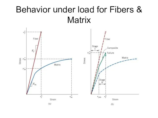
Слайд 22Behavior under load for Fibers & Matrix
Behavior under load for Fibers & Matrix
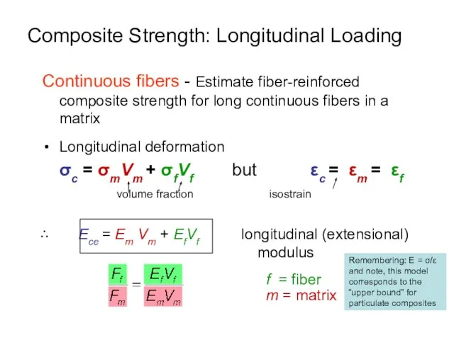
Слайд 23Composite Strength: Longitudinal Loading
Continuous fibers - Estimate fiber-reinforced composite strength for long
Composite Strength: Longitudinal Loading
Continuous fibers - Estimate fiber-reinforced composite strength for long
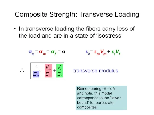
Слайд 24Composite Strength: Transverse Loading
In transverse loading the fibers carry less of the
Composite Strength: Transverse Loading
In transverse loading the fibers carry less of the
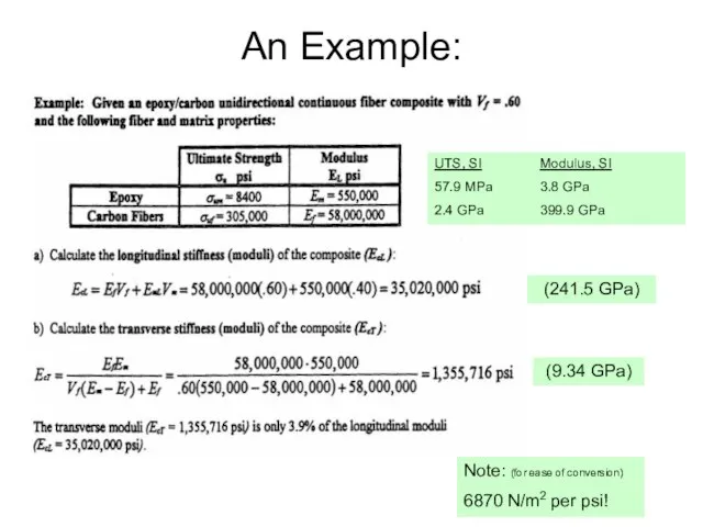
Слайд 25An Example:
Note: (for ease of conversion)
6870 N/m2 per psi!
UTS, SI Modulus, SI
57.9 MPa 3.8
An Example:
Note: (for ease of conversion)
6870 N/m2 per psi!
UTS, SI Modulus, SI
57.9 MPa 3.8
Слайд 26• Estimate of Ec and TS for discontinuous fibers:
-- valid when
--
• Estimate of Ec and TS for discontinuous fibers:
-- valid when
--
Слайд 27• Aligned Continuous fibers
• Examples:
From W. Funk and E. Blank, “Creep deformation
• Aligned Continuous fibers
• Examples:
From W. Funk and E. Blank, “Creep deformation
Слайд 28• Discontinuous, random 2D fibers
• Example: Carbon-Carbon
-- process: fiber/pitch, then
burn
• Discontinuous, random 2D fibers
• Example: Carbon-Carbon
-- process: fiber/pitch, then
burn
Слайд 29Looking at strength:
Looking at strength:
Слайд 30• Stacked and bonded fiber-reinforced sheets
-- stacking sequence: e.g., 0º/90º or
• Stacked and bonded fiber-reinforced sheets
-- stacking sequence: e.g., 0º/90º or
Слайд 31Composite Manufacturing Processes
Particulate Methods: Sintering
Fiber reinforced: Several
Structural: Usually Hand
Composite Manufacturing Processes
Particulate Methods: Sintering
Fiber reinforced: Several
Structural: Usually Hand
Слайд 33Open Mold Processes
Only one mold (male or female) is needed and may
Open Mold Processes
Only one mold (male or female) is needed and may

Слайд 34Hand Lay-Up: The resin and fiber (or pieces cut from prepreg) are
Hand Lay-Up: The resin and fiber (or pieces cut from prepreg) are
Слайд 35 A spray gun supplying resin in two converging streams into which
A spray gun supplying resin in two converging streams into which
Слайд 36Cut and lay the ply or prepreg under computer control and without
Cut and lay the ply or prepreg under computer control and without
Слайд 37Filament Winding
Ex: pressure tanks
Continuous filaments wound onto mandrel
Adapted from Fig. 16.15, Callister
Filament Winding
Ex: pressure tanks
Continuous filaments wound onto mandrel
Adapted from Fig. 16.15, Callister
Слайд 38 Filament Winding Characteristics
Because of the tension, reentrant shapes cannot be produced.
CNC
Filament Winding Characteristics
Because of the tension, reentrant shapes cannot be produced.
CNC
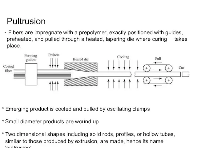
Слайд 39Pultrusion
Fibers are impregnate with a prepolymer, exactly positioned with guides, preheated,
Pultrusion
Fibers are impregnate with a prepolymer, exactly positioned with guides, preheated,
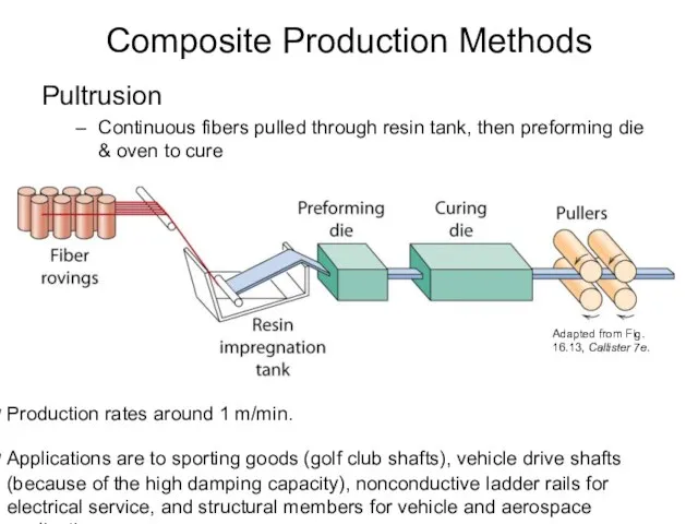
Слайд 40Composite Production Methods
Pultrusion
Continuous fibers pulled through resin tank, then preforming die &
Composite Production Methods
Pultrusion
Continuous fibers pulled through resin tank, then preforming die &
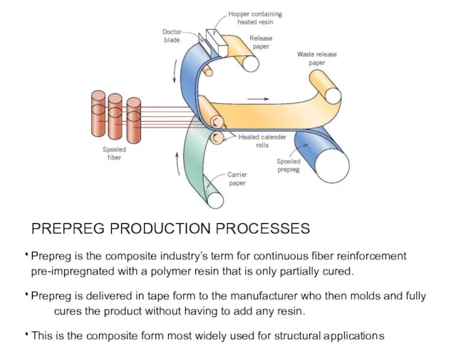
Слайд 41PREPREG PRODUCTION PROCESSES
Prepreg is the composite industry’s term for continuous fiber reinforcement
PREPREG PRODUCTION PROCESSES
Prepreg is the composite industry’s term for continuous fiber reinforcement
Слайд 42 Manufacturing begins by collimating a series of spool-wound continuous fiber tows.
Manufacturing begins by collimating a series of spool-wound continuous fiber tows.

Слайд 43 The final prepreg product is a thin tape consisting of continuous
The final prepreg product is a thin tape consisting of continuous
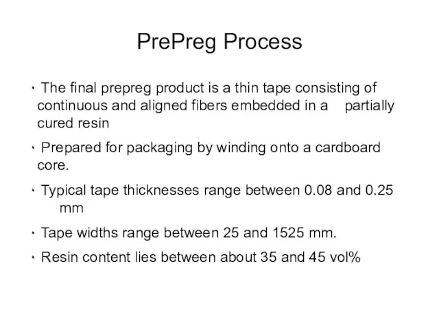
Слайд 44The prepreg is stored at 0°C (32 °F) or lower because thermoset
The prepreg is stored at 0°C (32 °F) or lower because thermoset

 ДИСТАНЦИОННЫЕ ТЕХНОЛОГИИ В НЕПРЕРЫВНОМ МЕДИЦИНСКОМ ОБРАЗОВАНИИ Проще чем Вы думаете
 Алгоритм методического анализа проведенного урока
 Сварочное производство
 Счастливые семьи
 Правоприменительный опыт Комиссии по справедливой торговле Кореи в фармацевтической отрасли
 #Шашники - школа аниматора Young
 Опухолевые маркеры:роль в клинической практике
 Презентация на тему Человек как уникальный вид живой природы
  Путешествие в мир пряничного теста
 The school system in Britain and Russia
 Жизнь и творчество Александра Николаевича Островского (1823-1886)
 Что нужно клиенту?
 Организация перевозки внешнеторговых грузов воздушным транспортом Дисциплина: Международные перевозки грузов Преподаватель: п
 Презентация на тему Фотоэлемент и его работа
 Правила поведения в ж/д транспорте
 Презентация на тему Диагностика предметной обученности
 Ты знаешь единицы измерения?
 Формулы сокращенного умножения
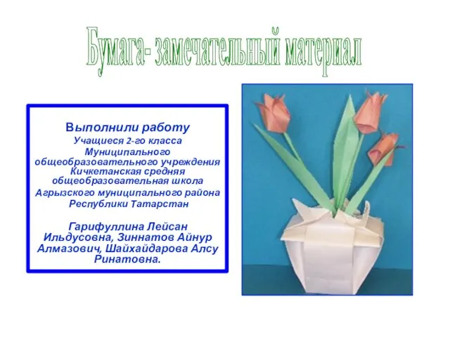 Бумага- замечательный материал
 Презентация на тему Мхи Папоротники Хвощи Плауны
 9 мая 9 мая - это всенародный праздник. Солдаты воевали, а женщины растили детей - будущее страны. Общими усилиями была достигнута поб
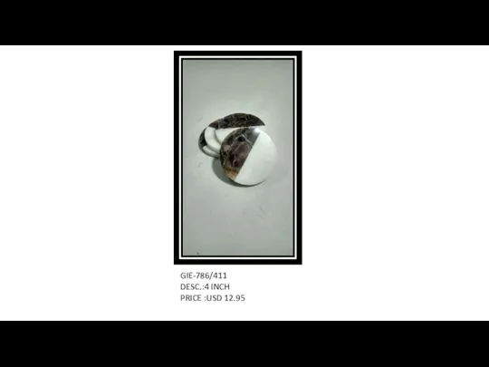 Natural semi precious stones
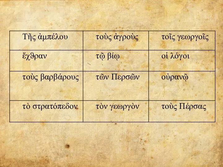 Определить род, падеж, число
 УНИВЕРСАЛЬНЫЕ УЧЕБНЫЕ ДЕЙСТВИЯ на уроках английского языка в начальной школе
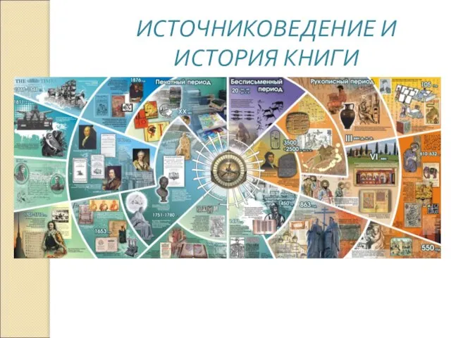 ИСТОЧНИКОВЕДЕНИЕ И ИСТОРИЯ КНИГИ
 ВКР: Социальное страхование в России: основные направления и пути совершенствования
 Пример построения системы управления машиностроительным производством
 Я люблю тебя