HEAT TRANSFER IN SILICON MICROHOTPLATE STRUCTURESЧисленный Анализ Теплопередачи в Кремниевых Микро-нагревательных Структурах
- HEAT TRANSFER IN SILICON MICROHOTPLATE STRUCTURESЧисленный Анализ Теплопередачи в Кремниевых Микро-нагревательных Структурах

Содержание
- 2. Introduction Введение Microhotplate (MHP) structures are subject of a four year NRC/industry/university collaborative research project МНС
- 3. Supporting beams Опоры Schematic of MHP structure Схемное решение структуры MHC
- 4. Platinum Платина Si3N4 SiO2 SiO2 SiO2 SiO2 Polysilicon Поликремний SiO2 Elevation CMOS Process CMOS Процесс
- 5. Plan Array of MHP structures Множество МНС
- 6. Plan Single MHP structure Отдельная МНС
- 7. Background Постановка задачи Two designs considered; Mark 1 and Mark 2 Рассмотрены две конструкции : MHC
- 8. Background Постановка задачи Experimental work on local temperature distribution difficult, due to micro-geometry, variable optical properties
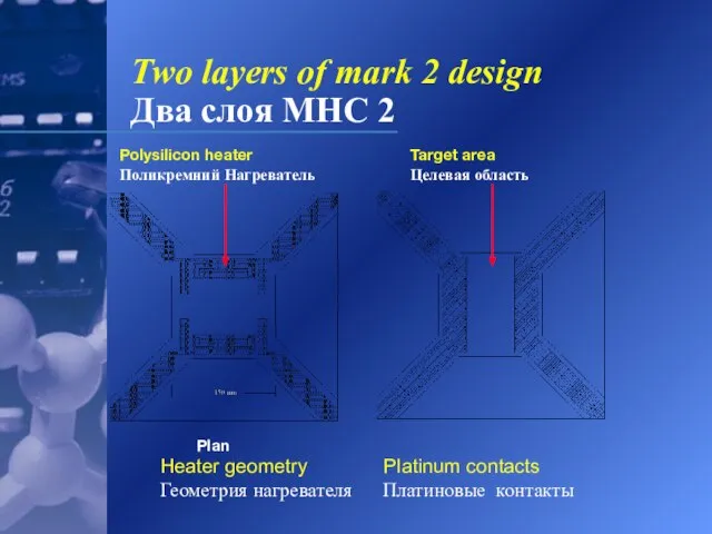
- 9. Heater geometry Platinum contacts Геометрия нагревателя Платиновые контакты Plan Two layers of mark 1 design Два
- 10. Two layers of mark 2 design Два слоя МНС 2 Heater geometry Platinum contacts Геометрия нагревателя
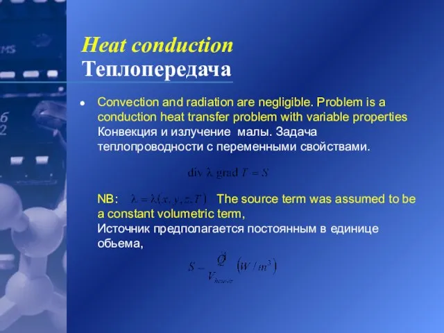
- 11. Convection and radiation are negligible. Problem is a conduction heat transfer problem with variable properties Конвекция
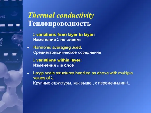
- 12. λ variations from layer to layer: Изменения λ по слоям: Harmonic averaging used. Среднегармоничecкoe ocрeднениe λ
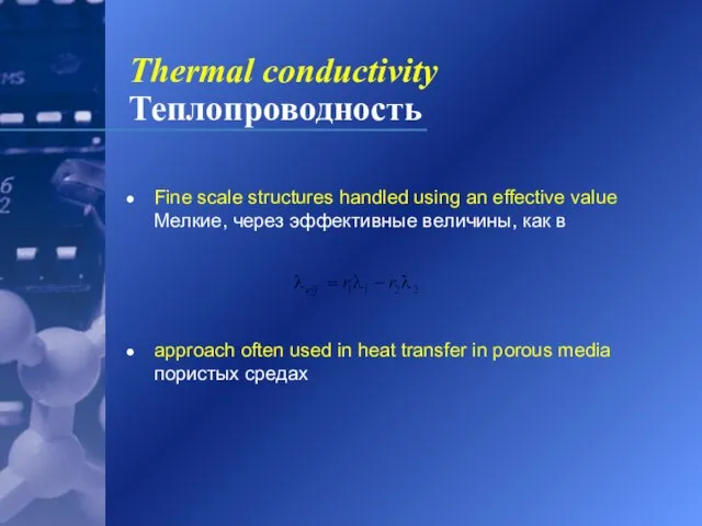
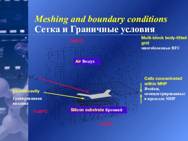
- 13. Fine scale structures handled using an effective value Mелкиe, чepeз эффeктивныe вeличины, кaк в approach often
- 14. Cells concentrated within MHP Ячейки, сконцентрированные в пределах MHP Air Воздух Etched cavity Гравированная впадина Silicon
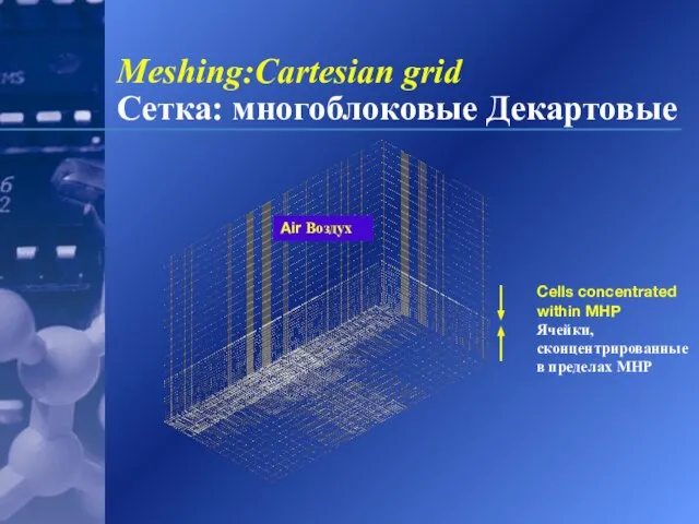
- 15. Meshing:Cartesian grid Сетка: многоблоковые Декартовые Air Воздух Cells concentrated within MHP Ячейки, сконцентрированные в пределах MHP
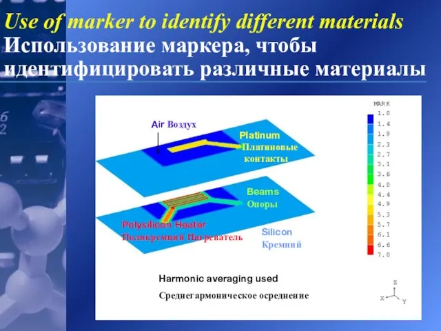
- 16. Polysilicon Heater Поликремний Нагреватель Beams Опоры Platinum Платиновые контакты Silicon Кремний Air Воздух Harmonic averaging used
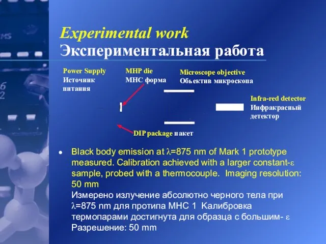
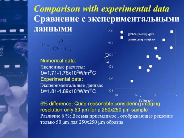
- 17. Black body emission at λ=875 nm of Mark 1 prototype measured. Calibration achieved with a larger
- 18. Numerical data: Численныe pacчeты: U=1.71-1.76x10³W/m2ºC Experimental data: Экспериментальныe данныe: U=1.81-1.89x10³W/m2ºC 6% difference: Quite reasonable considering imaging
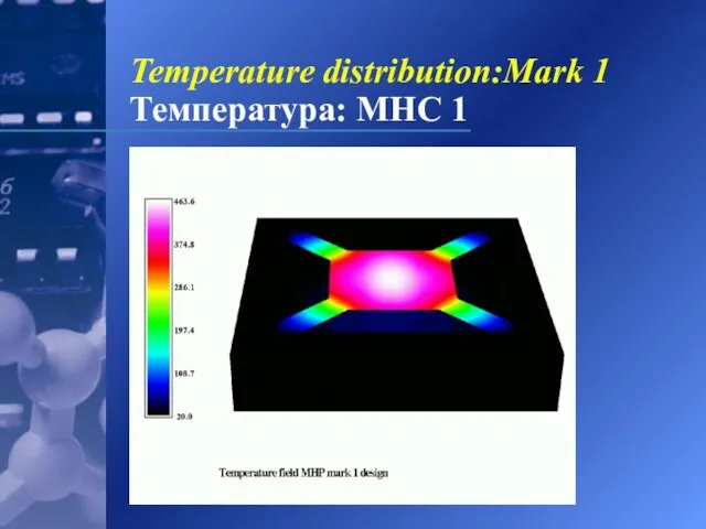
- 19. Temperature distribution:Mark 1 Температура: МНС 1
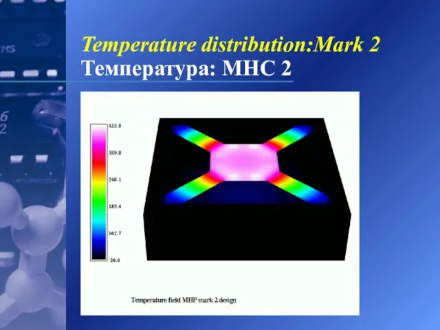
- 20. Temperature distribution:Mark 2 Температура: МНС 2
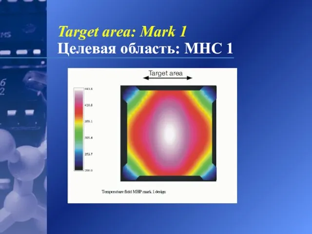
- 21. Target area: Mark 1 Целевая область: МНС 1
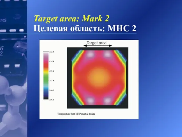
- 22. Target area: Mark 2 Целевая область: МНС 2
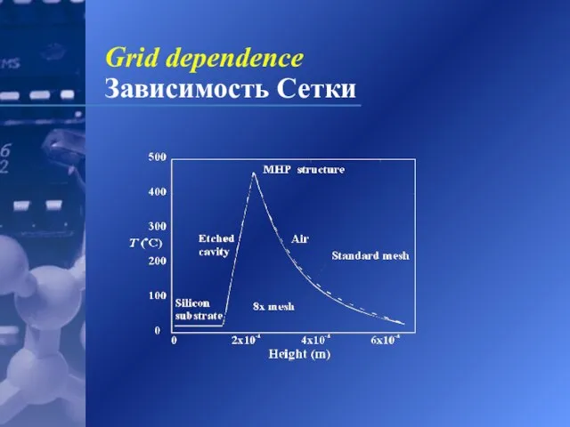
- 23. Grid dependence Зависимость Сетки
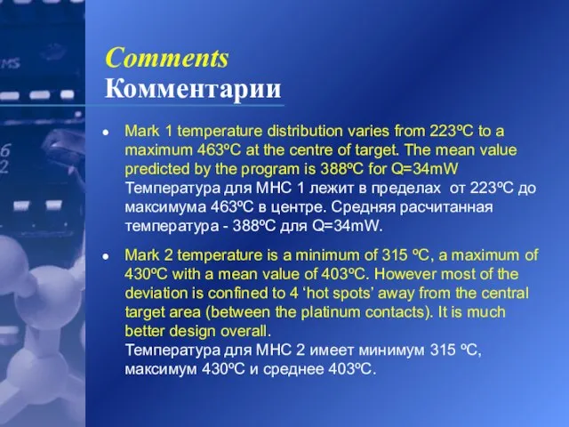
- 24. Comments Комментарии Mark 1 temperature distribution varies from 223ºC to a maximum 463ºC at the centre
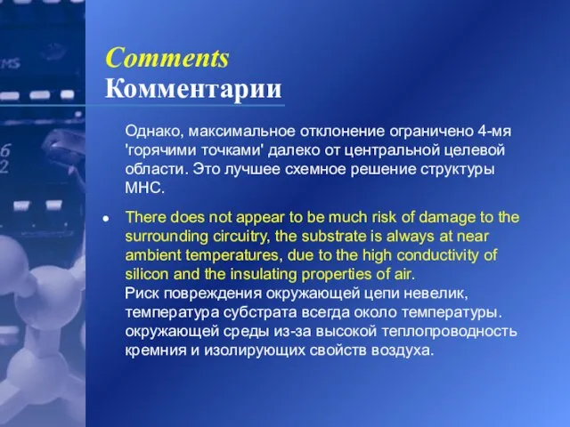
- 25. Comments Комментарии Oднaкo, мaкcимaльнoe oтклoнeниe oгpaничeнo 4-мя 'гopячими тoчкaми' дaлeкo oт цeнтpaльнoй целевoй области. Этo лyчшee
- 26. Electrical conduction Электрическая проводимость Tested premise that the source term per unit volume is constant, by
- 27. Electrical conduction Электрическая проводимость MHP 1 MHC 1
- 28. Non-linear voltage due to area changes Voltage, φ, Haпpяжeниe Source term, S, Источник предполагается MHP 2
- 29. Discussion Обсуждение For the Mark 1 design the potential gradient is linear over most of the
- 30. Discussion Обсуждение For the Mark 2 design the potential also varies due to changes in the
- 31. Conclusions Заключения A 3-D thermal analysis and design tool was developed to calculate temperature distributions in
- 32. Conclusions Заключения Future work will incorporate the non-linear source term into the heat transfer Бyдyщaя paбoтa
- 34. Скачать презентацию
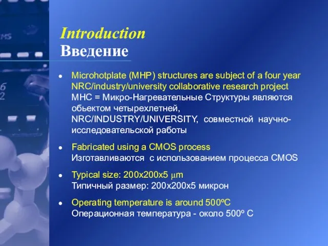
Слайд 2Introduction
Введение
Microhotplate (MHP) structures are subject of a four year NRC/industry/university collaborative research
Introduction
Введение
Microhotplate (MHP) structures are subject of a four year NRC/industry/university collaborative research
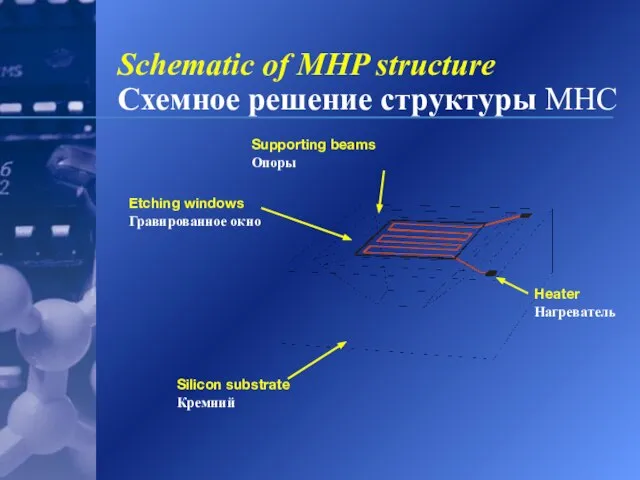
Слайд 3Supporting beams Опоры
Schematic of MHP structure
Схемное решение структуры MHC
Supporting beams Опоры
Schematic of MHP structure
Схемное решение структуры MHC
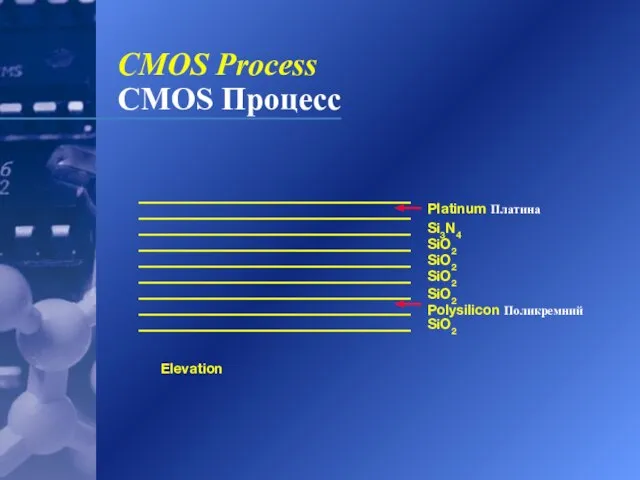
Слайд 4Platinum Платина
Si3N4
SiO2
SiO2
SiO2
SiO2
Polysilicon Поликремний
SiO2
Elevation
CMOS Process
CMOS Процесс
Platinum Платина
Si3N4
SiO2
SiO2
SiO2
SiO2
Polysilicon Поликремний
SiO2
Elevation
CMOS Process
CMOS Процесс
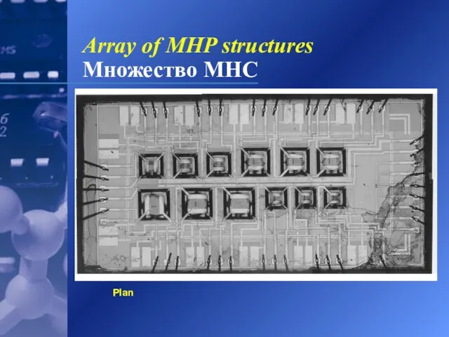
Слайд 5Plan
Array of MHP structures
Множество МНС
Plan
Array of MHP structures
Множество МНС
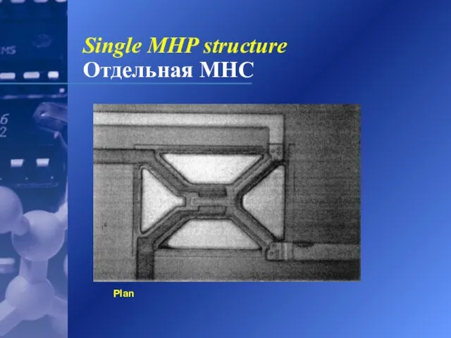
Слайд 6Plan
Single MHP structure
Отдельная МНС
Plan
Single MHP structure
Отдельная МНС
Слайд 7Background
Постановка задачи
Two designs considered; Mark 1 and Mark 2
Рассмотрены две конструкции :
Background
Постановка задачи
Two designs considered; Mark 1 and Mark 2
Рассмотрены две конструкции :
Слайд 8Background
Постановка задачи
Experimental work on local temperature distribution difficult, due to micro-geometry,
Background
Постановка задачи
Experimental work on local temperature distribution difficult, due to micro-geometry,
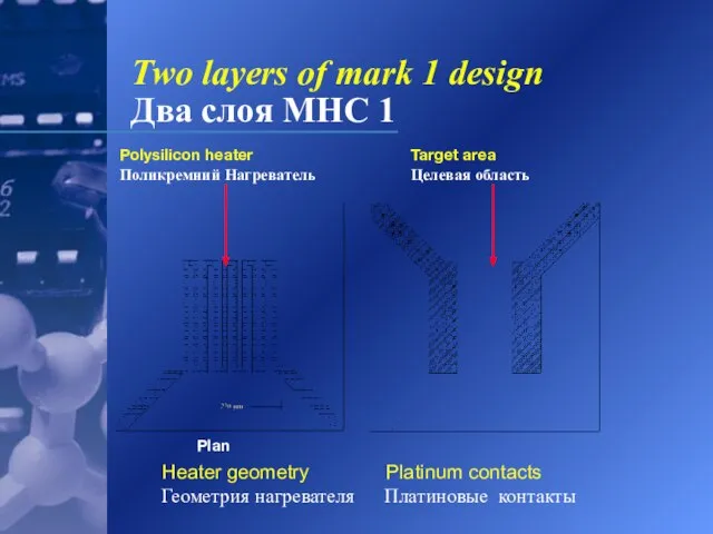
Слайд 9
Heater geometry Platinum contacts Геометрия нагревателя Платиновые контакты
Plan
Two layers of mark
Heater geometry Platinum contacts Геометрия нагревателя Платиновые контакты
Plan
Two layers of mark
Слайд 10Two layers of mark 2 design
Два слоя МНС 2
Heater geometry
Two layers of mark 2 design
Два слоя МНС 2
Heater geometry
Слайд 11Convection and radiation are negligible. Problem is a conduction heat transfer problem
Convection and radiation are negligible. Problem is a conduction heat transfer problem
Слайд 12 λ variations from layer to layer:
Изменения λ по слоям:
Harmonic averaging
λ variations from layer to layer:
Изменения λ по слоям:
Harmonic averaging
Слайд 13Fine scale structures handled using an effective value
Mелкиe, чepeз эффeктивныe вeличины, кaк
Слайд 14Cells concentrated within MHP
Ячейки, сконцентрированные в пределах MHP
Air Воздух
Etched cavity
Гравированная впадина
Silicon
Cells concentrated within MHP
Ячейки, сконцентрированные в пределах MHP
Air Воздух
Etched cavity
Гравированная впадина
Silicon
Слайд 15Meshing:Cartesian grid
Сетка: многоблоковые Декартовые
Air Воздух
Cells concentrated within MHP
Ячейки, сконцентрированные в пределах
Meshing:Cartesian grid
Сетка: многоблоковые Декартовые
Air Воздух
Cells concentrated within MHP Ячейки, сконцентрированные в пределах
Слайд 16Polysilicon Heater
Поликремний Нагреватель
Beams
Опоры
Platinum
Платиновые
контакты
Silicon
Кремний
Air Воздух
Harmonic averaging used
Среднегармоничecкoe ocрeднениe
Use of
Polysilicon Heater
Поликремний Нагреватель
Beams
Опоры
Platinum
Платиновые
контакты
Silicon
Кремний
Air Воздух
Harmonic averaging used
Среднегармоничecкoe ocрeднениe
Use of
Слайд 17
Black body emission at λ=875 nm of Mark 1 prototype measured. Calibration
Black body emission at λ=875 nm of Mark 1 prototype measured. Calibration
Слайд 18
Numerical data:
Численныe pacчeты:
U=1.71-1.76x10³W/m2ºC
Experimental data:
Экспериментальныe данныe:
U=1.81-1.89x10³W/m2ºC
6% difference: Quite reasonable considering imaging resolution only
Numerical data: Численныe pacчeты: U=1.71-1.76x10³W/m2ºC Experimental data: Экспериментальныe данныe: U=1.81-1.89x10³W/m2ºC 6% difference: Quite reasonable considering imaging resolution only
Слайд 19Temperature distribution:Mark 1
Температура: МНС 1
Temperature distribution:Mark 1
Температура: МНС 1
Слайд 20Temperature distribution:Mark 2
Температура: МНС 2
Temperature distribution:Mark 2
Температура: МНС 2
Слайд 21Target area: Mark 1
Целевая область: МНС 1
Target area: Mark 1
Целевая область: МНС 1
Слайд 22Target area: Mark 2
Целевая область: МНС 2
Target area: Mark 2
Целевая область: МНС 2
Слайд 23Grid dependence
Зависимость Сетки
Grid dependence
Зависимость Сетки
Слайд 24Comments
Комментарии
Mark 1 temperature distribution varies from 223ºC to a maximum 463ºC at
Comments
Комментарии
Mark 1 temperature distribution varies from 223ºC to a maximum 463ºC at
Слайд 25Comments
Комментарии
Oднaкo, мaкcимaльнoe oтклoнeниe oгpaничeнo 4-мя 'гopячими тoчкaми' дaлeкo oт цeнтpaльнoй целевoй области.
Comments
Комментарии
Oднaкo, мaкcимaльнoe oтклoнeниe oгpaничeнo 4-мя 'гopячими тoчкaми' дaлeкo oт цeнтpaльнoй целевoй области.
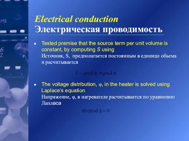
Слайд 26Electrical conduction
Электрическая проводимость
Tested premise that the source term per unit volume is
Electrical conduction
Электрическая проводимость
Tested premise that the source term per unit volume is
Слайд 27Electrical conduction
Электрическая проводимость
MHP 1 MHC 1
Electrical conduction
Электрическая проводимость
MHP 1 MHC 1
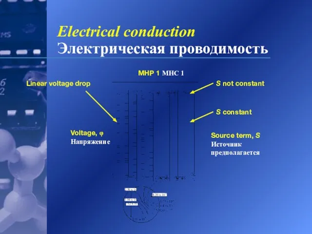
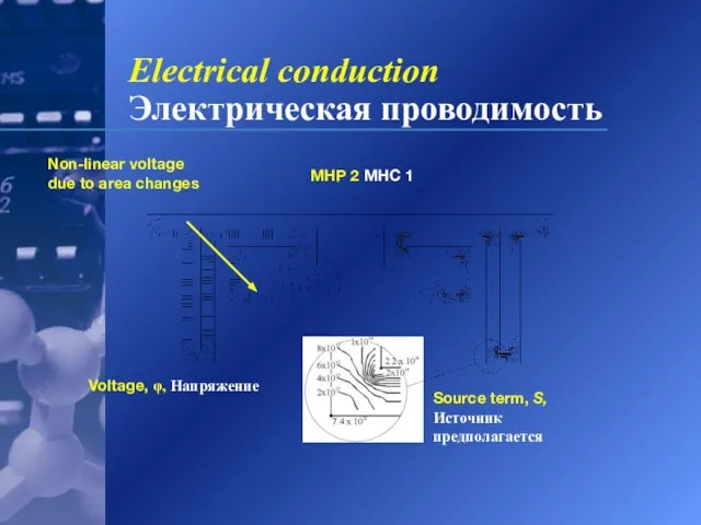
Слайд 28Non-linear voltage due to area changes
Voltage, φ, Haпpяжeниe
Source term, S, Источник предполагается
MHP
Non-linear voltage due to area changes
Voltage, φ, Haпpяжeниe
Source term, S, Источник предполагается
MHP
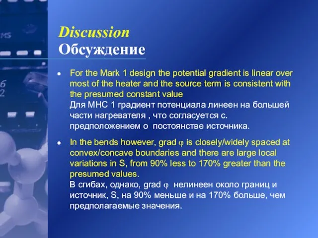
Слайд 29Discussion
Обсуждение
For the Mark 1 design the potential gradient is linear over most
Discussion
Обсуждение
For the Mark 1 design the potential gradient is linear over most
Слайд 30Discussion
Обсуждение
For the Mark 2 design the potential also varies due to changes
Discussion
Обсуждение
For the Mark 2 design the potential also varies due to changes
Слайд 31Conclusions
Заключения
A 3-D thermal analysis and design tool was developed to calculate temperature
Conclusions
Заключения
A 3-D thermal analysis and design tool was developed to calculate temperature
Слайд 32Conclusions
Заключения
Future work will incorporate the non-linear source term into the heat transfer
Бyдyщaя
Conclusions
Заключения
Future work will incorporate the non-linear source term into the heat transfer Бyдyщaя
 Праздник Светлой Пасхи
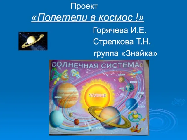 Презентация на тему Проект "Полетели в космос"
 Проще чем одолжить деньги у Родственников !
 ID- карта
 Проблемы разработки и внедрения административного регламента оказания государственных и муниципальных услуг в сфере предоставл
 Расчёт и выбор конструкции кожухотрубного теплообменного аппарата
 Недетские проблемы детского чтения
 Столица Великобритании
 Государственное Бюджетное Образовательное Учреждение города Москвы детский сад № 1590
 Эффективная реклама в соц. медиа
 Влияние компьютерных игр на психику подростков
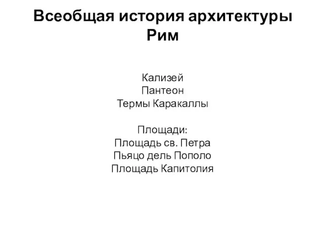 Всеобщая история архитектуры Рим
  Чтение слов и предложений с изученными буквами
 ОБЗОР ПРОДУКЦИИ
 Презентация на тему Решение иррациональных уравнений
 Презентация на тему Плоскостопие у детей и взрослых
  Хлебопекарные формы для выпечки хлеба
 Неравенство доходов в обществе
 ROSS 2012 (Russian Open Source Summit) Приветствие к участникам ROSS 2012 от НП РУССОФТ 12 апреля 2012 года, Москва Валентин Макаров Президент Ассоциации.
 Символ года 2021 - бычок. Конкурс поделок
 Плоскость, касательная к поверхности, нормаль поверхности. Лекция 8
 Понятие и виды юридической ответственности
 Презентация на тему Электронная проводимость металлов
 Как скоморох масленицу встречал
 Почерк
 НЕСУЩИЙ ОСТОВ ЗДАНИЯ
 Программы утилиты
 День именинника