- How to draw the tolerance zone by nominal and limited dimensions (Seminar 1)

Содержание
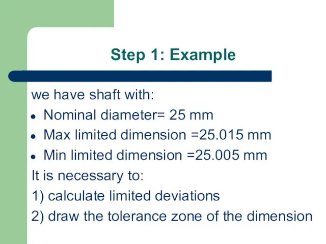
- 2. Step 1: Example we have shaft with: Nominal diameter= 25 mm Max limited dimension =25.015 mm
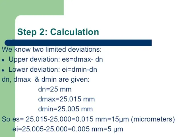
- 3. Step 2: Calculation We know two limited deviations: Upper deviation: es=dmax- dn Lower deviation: ei=dmin-dn dn,
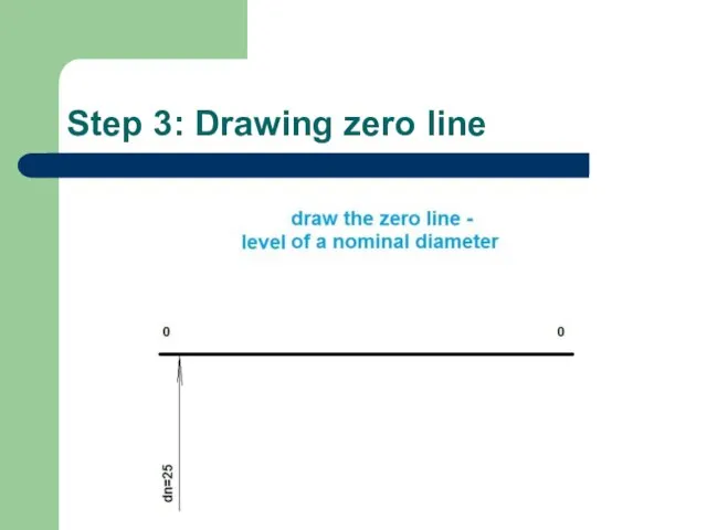
- 4. Step 3: Drawing zero line
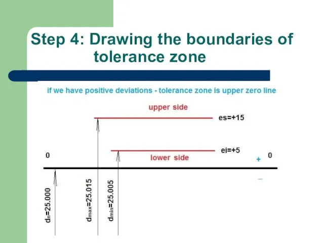
- 5. Step 4: Drawing the boundaries of tolerance zone
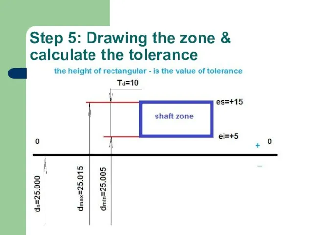
- 6. Step 5: Drawing the zone & calculate the tolerance
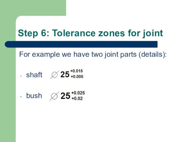
- 7. Step 6: Tolerance zones for joint For example we have two joint parts (details): shaft bush
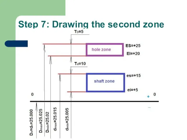
- 8. Step 7: Drawing the second zone
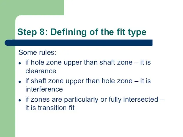
- 9. Step 8: Defining of the fit type Some rules: if hole zone upper than shaft zone
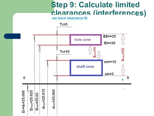
- 10. Step 9: Calculate limited clearances (interferences)
- 12. Скачать презентацию
Слайд 3Step 2: Calculation
We know two limited deviations:
Upper deviation: es=dmax- dn
Lower deviation: ei=dmin-dn
dn,
Step 2: Calculation
We know two limited deviations:
Upper deviation: es=dmax- dn
Lower deviation: ei=dmin-dn
dn,
Слайд 4Step 3: Drawing zero line
Step 3: Drawing zero line
Слайд 5Step 4: Drawing the boundaries of tolerance zone
Step 4: Drawing the boundaries of tolerance zone
Слайд 6Step 5: Drawing the zone & calculate the tolerance
Step 5: Drawing the zone & calculate the tolerance
Слайд 7Step 6: Tolerance zones for joint
For example we have two joint
Step 6: Tolerance zones for joint
For example we have two joint
Слайд 8Step 7: Drawing the second zone
Step 7: Drawing the second zone
Слайд 9Step 8: Defining of the fit type
Some rules:
if hole zone upper than
Step 8: Defining of the fit type
Some rules:
if hole zone upper than
Слайд 10Step 9: Calculate limited clearances (interferences)
Step 9: Calculate limited clearances (interferences)
 Нанороботы
 Отходы. Утилизация отходов
 Лидия Прхиповна Кузнецова (Уварова). Скульптор города Лысьвы 15.01.1934 – 15.08.2014
 Лекция 6. Показатели эффективности
 ВЗАИМОДЕЙСТВИЕ КЛАССНОГО РУКОВОДИТЕЛЯ С РОДИТЕЛЯМИ ( из практического опыта)
 Всеобщая декларация прав человека
 Фильтры/кондиционеры охлаждающей жидкости
 Блок обучения. Для сотрудников Компании “Шин Line”
 Der Dolmetscher
 Синтез наночастиц серебра
 Высокий старт. Билимбай 1941-1943 гг. Реактивное самолётостроение. Вертолётостроение. Космонавтика
 Все люди от природы стремятся к знанию.Аристотель.
 Экономические школы
 Шаблон презентации проекта
 Национальная книжная палата БеларусиЕрмолич Елена Ивановна
 Субъекты гражданского права
 Как выводить глубоко офлайновые компании в есот
 1Национальный центр развития философии и искусств «Большая Волхонка»
 Церковь и государство в XV - начале XVI вв
 Мастер-классы
 Москва - город, в котором мы живем
 Тех лет не смолкнет слава. Герои - артековцы
 Введение ФГОС
 11. КТтрон от ТехПром
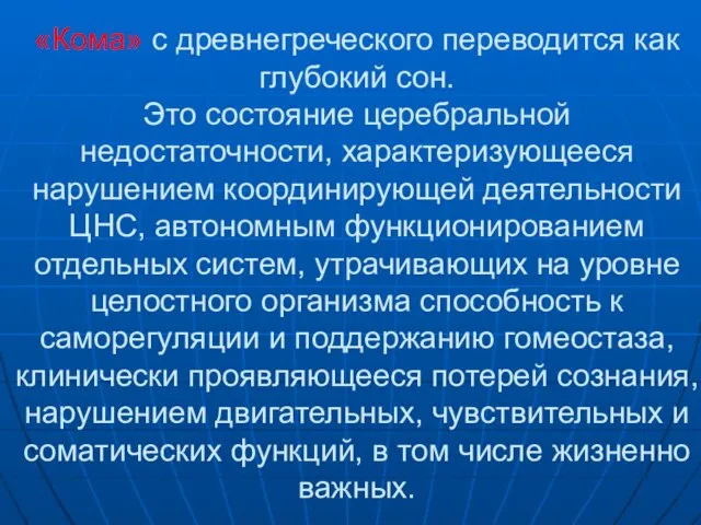 Кома
Кома  Вышивка крестом 7 класс
 Русский язык. 2 класс
 Лепка из пластилина. Резьба по кости