- slides topic9

Содержание
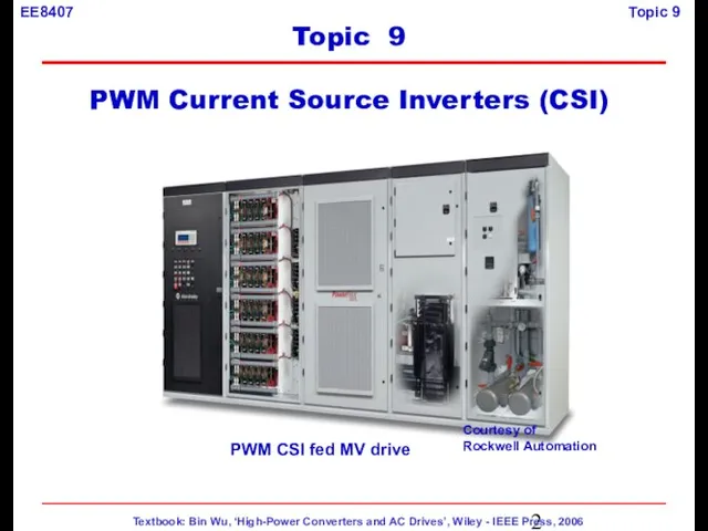
- 2. PWM CSI fed MV drive Topic 9 PWM Current Source Inverters (CSI) Courtesy of Rockwell Automation
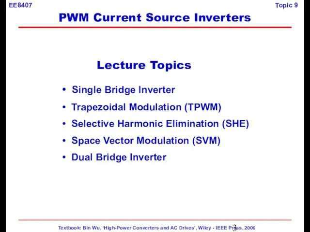
- 3. Lecture Topics Single Bridge Inverter Trapezoidal Modulation (TPWM) Selective Harmonic Elimination (SHE) Space Vector Modulation (SVM)
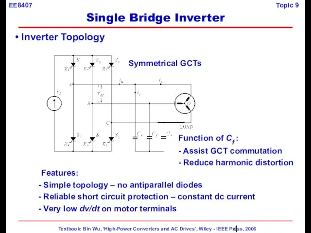
- 4. Inverter Topology Features: Simple topology – no antiparallel diodes Reliable short circuit protection – constant dc
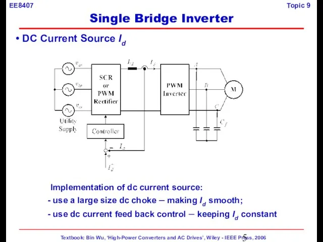
- 5. DC Current Source Id Implementation of dc current source: use a large size dc choke –
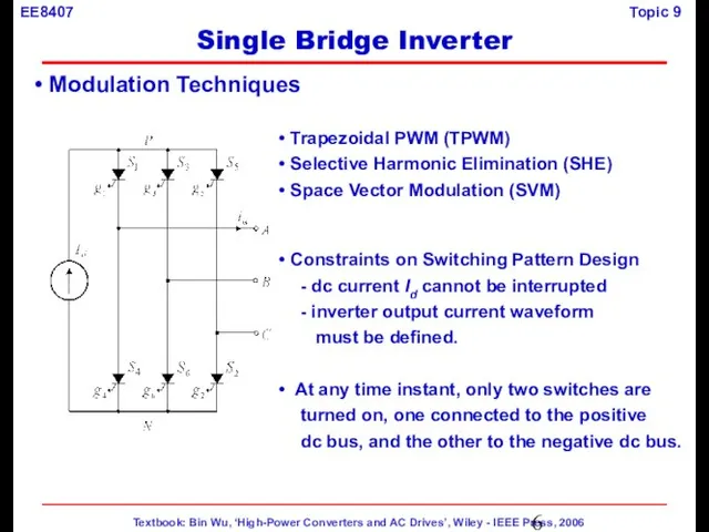
- 6. Trapezoidal PWM (TPWM) Selective Harmonic Elimination (SHE) Space Vector Modulation (SVM) Constraints on Switching Pattern Design
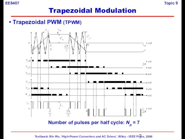
- 7. Trapezoidal PWM (TPWM) Number of pulses per half cycle: Np = 7 Trapezoidal Modulation
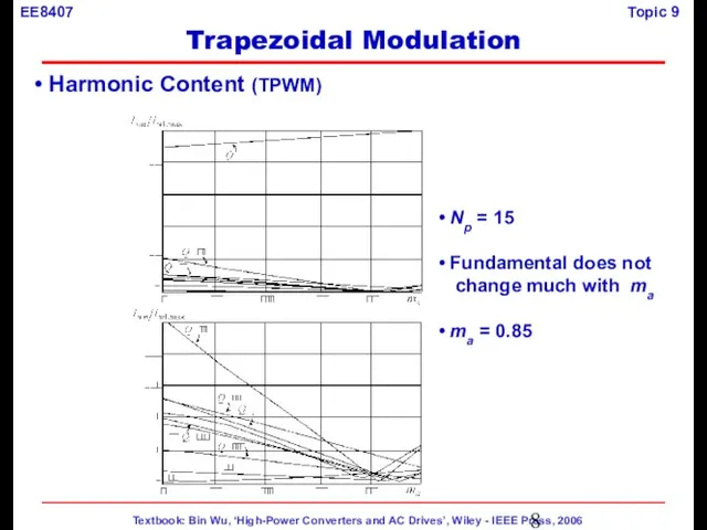
- 8. Harmonic Content (TPWM) Np = 15 Fundamental does not change much with ma ma = 0.85
- 9. Waveforms (TPWM) Trapezoidal Modulation
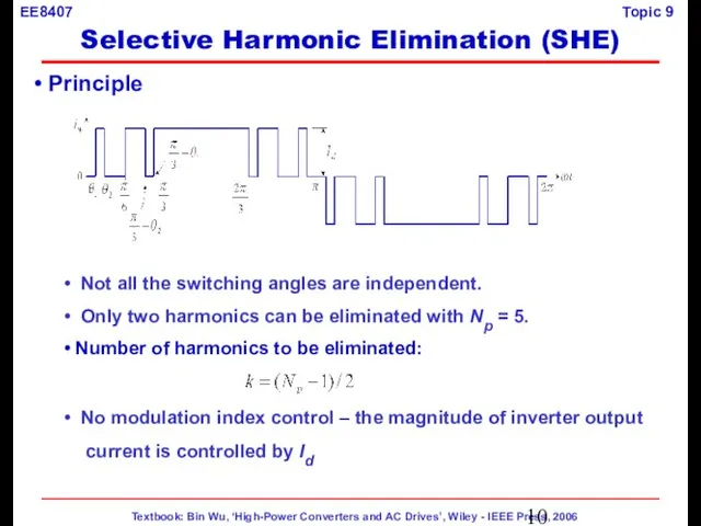
- 10. Principle Not all the switching angles are independent. Only two harmonics can be eliminated with Np
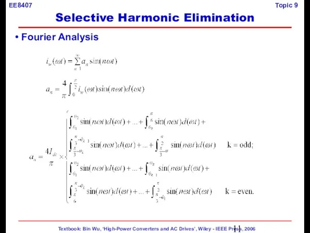
- 11. Fourier Analysis Selective Harmonic Elimination
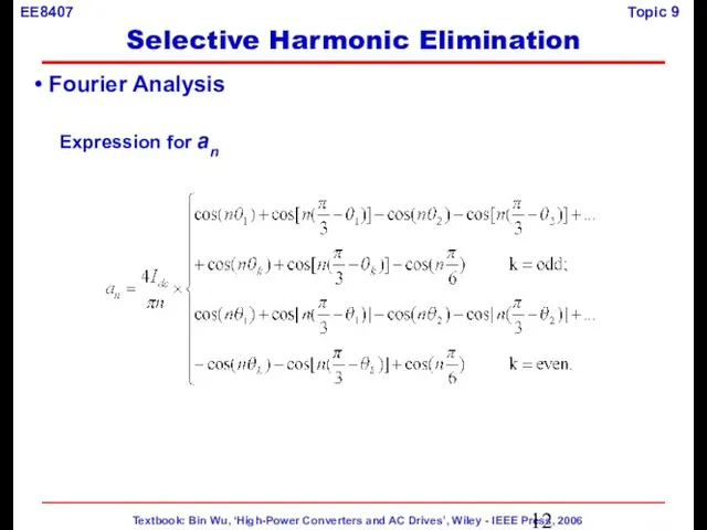
- 12. Expression for an Fourier Analysis Selective Harmonic Elimination
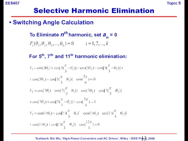
- 13. Switching Angle Calculation To Eliminate nth harmonic, set an = 0 For 5th, 7th and 11th
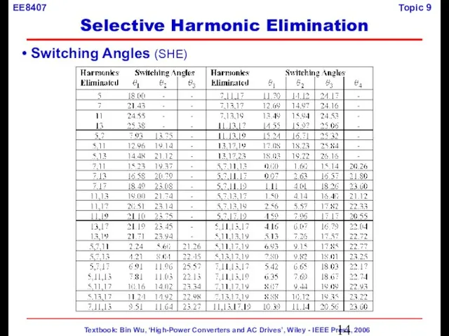
- 14. Switching Angles (SHE) Selective Harmonic Elimination
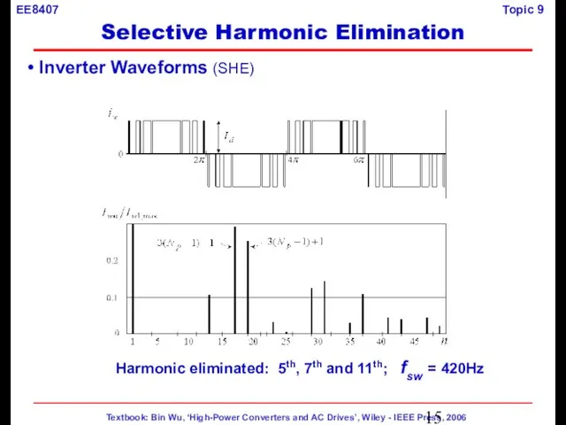
- 15. Inverter Waveforms (SHE) Harmonic eliminated: 5th, 7th and 11th; fsw = 420Hz Selective Harmonic Elimination
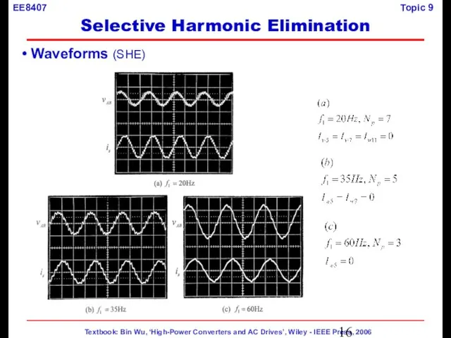
- 16. Waveforms (SHE) Selective Harmonic Elimination
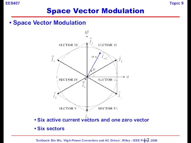
- 17. Space Vector Modulation Six active current vectors and one zero vector Six sectors Space Vector Modulation
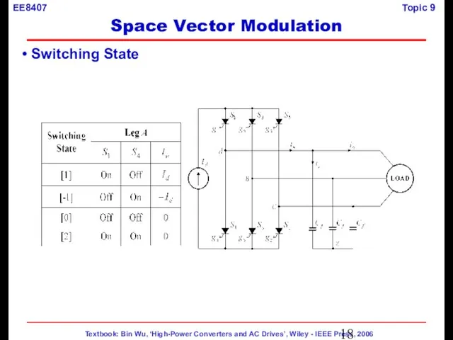
- 18. Switching State Space Vector Modulation
- 19. Switching States & Space Vectors [1]: Upper switch on [-1]: Lower switch on [0]: None of
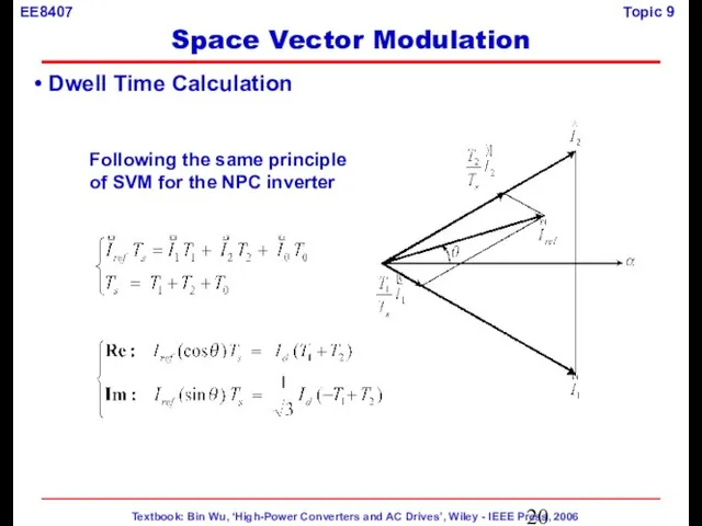
- 20. Dwell Time Calculation Following the same principle of SVM for the NPC inverter Space Vector Modulation
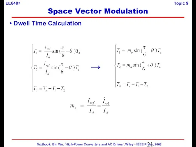
- 21. Dwell Time Calculation → Space Vector Modulation
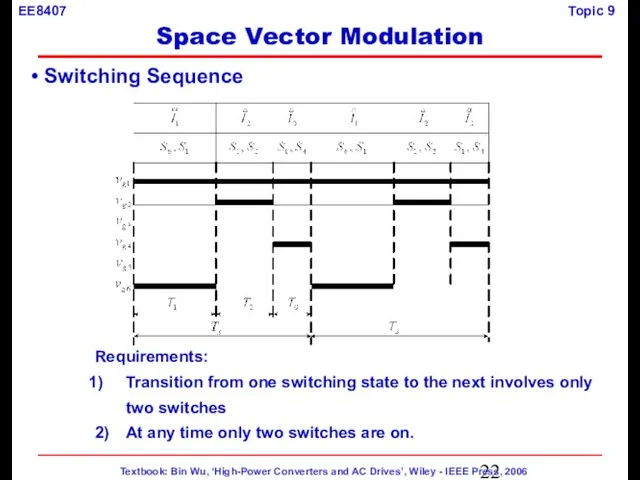
- 22. Switching Sequence Requirements: Transition from one switching state to the next involves only two switches 2)
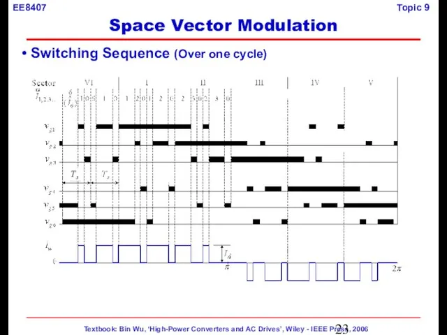
- 23. Switching Sequence (Over one cycle) Space Vector Modulation
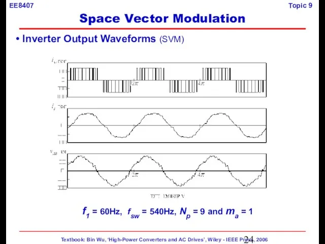
- 24. Inverter Output Waveforms (SVM) f1 = 60Hz, fsw = 540Hz, Np = 9 and ma =
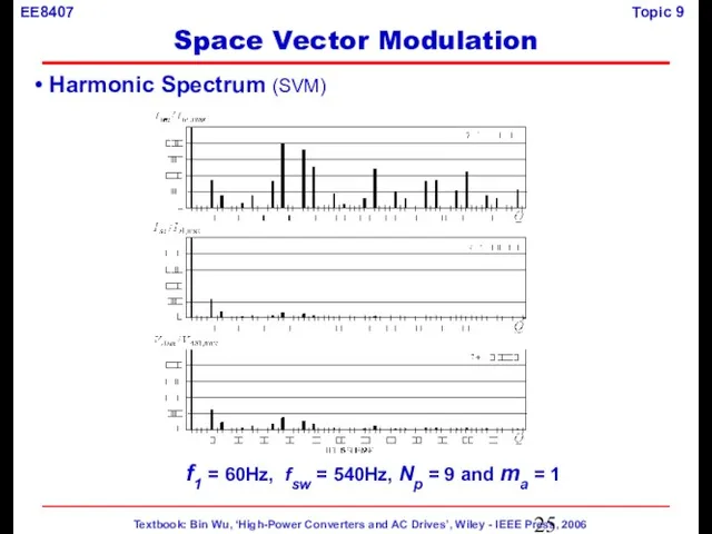
- 25. Harmonic Spectrum (SVM) f1 = 60Hz, fsw = 540Hz, Np = 9 and ma = 1
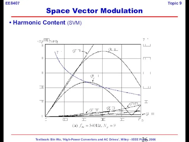
- 26. Harmonic Content (SVM) Space Vector Modulation
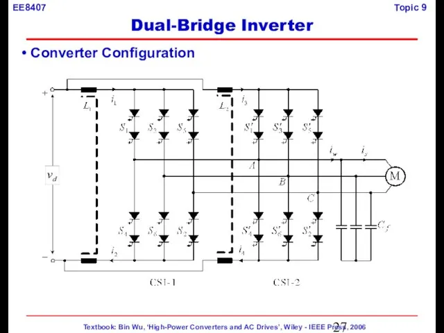
- 27. Converter Configuration Dual-Bridge Inverter
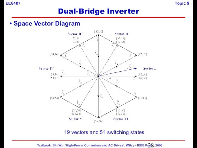
- 28. Space Vector Diagram 19 vectors and 51 switching states Dual-Bridge Inverter
- 29. Current paths with switching state [16;56] DC Current Balance Control Dual-Bridge Inverter
- 30. DC Current Balance Control Current paths with switching state [16;56] Dual-Bridge Inverter
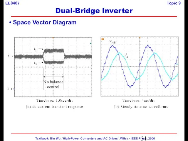
- 31. Space Vector Diagram Dual-Bridge Inverter
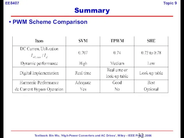
- 32. PWM Scheme Comparison Summary
- 34. Скачать презентацию
Слайд 3 Lecture Topics
Single Bridge Inverter
Trapezoidal Modulation (TPWM)
Selective Harmonic
Lecture Topics
Single Bridge Inverter
Trapezoidal Modulation (TPWM)
Selective Harmonic
Слайд 4 Inverter Topology
Features:
Simple topology – no antiparallel diodes
Reliable short circuit
Inverter Topology
Features:
Simple topology – no antiparallel diodes
Reliable short circuit
Слайд 5 DC Current Source Id
Implementation of dc current source:
use a large
DC Current Source Id
Implementation of dc current source:
use a large
Слайд 6 Trapezoidal PWM (TPWM)
Selective Harmonic Elimination (SHE)
Space Vector Modulation (SVM)
Trapezoidal PWM (TPWM)
Selective Harmonic Elimination (SHE)
Space Vector Modulation (SVM)
Слайд 7 Trapezoidal PWM (TPWM)
Number of pulses per half cycle: Np = 7
Trapezoidal
Trapezoidal PWM (TPWM)
Number of pulses per half cycle: Np = 7
Trapezoidal
Слайд 8 Harmonic Content (TPWM)
Np = 15
Fundamental does not
change much
Harmonic Content (TPWM)
Np = 15
Fundamental does not
change much
Слайд 9 Waveforms
(TPWM)
Trapezoidal Modulation
Waveforms
(TPWM)
Trapezoidal Modulation

Слайд 10 Principle
Not all the switching angles are independent.
Only two harmonics
Principle
Not all the switching angles are independent.
Only two harmonics
Слайд 11 Fourier Analysis
Selective Harmonic Elimination
Fourier Analysis
Selective Harmonic Elimination
Слайд 12Expression for an
Fourier Analysis
Selective Harmonic Elimination
Expression for an
Fourier Analysis
Selective Harmonic Elimination
Слайд 13 Switching Angle Calculation
To Eliminate nth harmonic, set an = 0
For
Switching Angle Calculation
To Eliminate nth harmonic, set an = 0
For
Слайд 14 Switching Angles (SHE)
Selective Harmonic Elimination
Switching Angles (SHE)
Selective Harmonic Elimination
Слайд 15 Inverter Waveforms (SHE)
Harmonic eliminated: 5th, 7th and 11th; fsw = 420Hz
Selective
Inverter Waveforms (SHE)
Harmonic eliminated: 5th, 7th and 11th; fsw = 420Hz
Selective
Слайд 16 Waveforms (SHE)
Selective Harmonic Elimination
Waveforms (SHE)
Selective Harmonic Elimination
Слайд 17 Space Vector Modulation
Six active current vectors and one zero vector
Space Vector Modulation
Six active current vectors and one zero vector
Слайд 18 Switching State
Space Vector Modulation
Switching State
Space Vector Modulation
Слайд 19 Switching States & Space Vectors
[1]: Upper switch on
[-1]: Lower switch on
[0]:
Switching States & Space Vectors
[1]: Upper switch on
[-1]: Lower switch on
[0]:
![Switching States & Space Vectors [1]: Upper switch on [-1]: Lower switch](/_ipx/f_webp&q_80&fit_contain&s_1440x1080/imagesDir/jpg/381593/slide-18.jpg)
Слайд 20 Dwell Time Calculation
Following the same principle
of SVM for the NPC inverter
Space
Dwell Time Calculation
Following the same principle
of SVM for the NPC inverter
Space
Слайд 21 Dwell Time Calculation
→
Space Vector Modulation
Dwell Time Calculation
→
Space Vector Modulation
Слайд 22 Switching Sequence
Requirements:
Transition from one switching state to the next involves
Switching Sequence
Requirements:
Transition from one switching state to the next involves
Слайд 23 Switching Sequence (Over one cycle)
Space Vector Modulation
Switching Sequence (Over one cycle)
Space Vector Modulation
Слайд 24 Inverter Output Waveforms (SVM)
f1 = 60Hz, fsw = 540Hz, Np =
Inverter Output Waveforms (SVM)
f1 = 60Hz, fsw = 540Hz, Np =
Слайд 25 Harmonic Spectrum (SVM)
f1 = 60Hz, fsw = 540Hz, Np = 9
Harmonic Spectrum (SVM)
f1 = 60Hz, fsw = 540Hz, Np = 9
Слайд 26 Harmonic Content (SVM)
Space Vector Modulation
Harmonic Content (SVM)
Space Vector Modulation
Слайд 27 Converter Configuration
Dual-Bridge Inverter
Converter Configuration
Dual-Bridge Inverter
Слайд 28 Space Vector Diagram
19 vectors and 51 switching states
Dual-Bridge Inverter
Space Vector Diagram
19 vectors and 51 switching states
Dual-Bridge Inverter
Слайд 29Current paths with switching state [16;56]
DC Current Balance Control
Dual-Bridge
Current paths with switching state [16;56]
DC Current Balance Control
Dual-Bridge
![Current paths with switching state [16;56] DC Current Balance Control Dual-Bridge Inverter](/_ipx/f_webp&q_80&fit_contain&s_1440x1080/imagesDir/jpg/381593/slide-28.jpg)
Слайд 30 DC Current Balance Control
Current paths with switching state [16;56]
Dual-Bridge
DC Current Balance Control
Current paths with switching state [16;56]
Dual-Bridge
![DC Current Balance Control Current paths with switching state [16;56] Dual-Bridge Inverter](/_ipx/f_webp&q_80&fit_contain&s_1440x1080/imagesDir/jpg/381593/slide-29.jpg)
Слайд 31 Space Vector Diagram
Dual-Bridge Inverter
Space Vector Diagram
Dual-Bridge Inverter
Слайд 32 PWM Scheme Comparison
Summary
PWM Scheme Comparison
Summary
 Автоматическая пожарная сигнализация
 Как единое информационное пространство поможет научно-образовательным центрам решить задачи эффективности
 Репьевка
 Астрология. Астропрогноз
 Исследовательская работа Что мы знаем о чипсах?
 Плетение. Пояс, сплетённый из лент. Поэтапное выполнение
 Программа посткризисного восстановления (оздоровление конкурентоспособных предприятий)
 Геометрия архитектурной гармонии
 aukcion_znaniy_5-8_klassy
 ХИМИЯ ЭЛЕМЕНТОВ ПОДГРУППЫ АЛЮМИНИЯ
 Стратификация языка. Ярусы языковой системы
 Wildlife and Fisheries Resource Governance
 Салтыков-Щедрин Сказки
 Презентация на тему Солнечная активность
  Десерт Шокомяч
 Построение и эксплуатация систем коммутации сетей шифрованной телефонной связи
 Актуальные вопросы реализации 225-ФЗ
 Трудовое право
 Жизнь прекрасна
 Великая Отечественная война 1941 – 1945 гг. Мы помним. Мы не имеем права забыть подвиг, который совершил российский народ. Мы помним стр
 Профессионально важные качества
 Цикличность развития бизнеса и роль HR-функции в компании
 Жан Пиаже
 Marketing
  Лексикология и фразеология
 Презентация на тему Австралия
  Композиция
 Зачем ежу яблоки