- UML_Lecture

Содержание
- 2. About myself Yi Luo TA for EEL5881 3rd Year Phd student in CpE Email: [email protected] Office
- 3. Acknowledgements Slides material are taken from different sources including: the slides of Mr. Shiyuan Jin’s UML
- 4. Outline What is UML and why we use UML? How to use UML diagrams to design
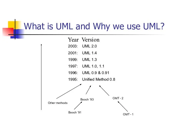
- 5. What is UML and Why we use UML? UML → “Unified Modeling Language” Language: express idea,
- 6. What is UML and Why we use UML? More description about UML: It is a industry-standard
- 7. What is UML and Why we use UML? Why we use UML? Use graphical notation: more
- 8. What is UML and Why we use UML?
- 9. How to use UML diagrams to design software system? Types of UML Diagrams: Use Case Diagram
- 10. Use-Case Diagrams A use-case diagram is a set of use cases A use case is a
- 11. Use-Case Diagrams Library System Borrow Order Title Fine Remittance Client Employee Supervisor Boundary Actor Use Case
- 12. Use-Case Diagrams Actors: A role that a user plays with respect to the system, including human
- 13. Use-Case Diagrams Association: communication between an actor and a use case; Represented by a solid line.
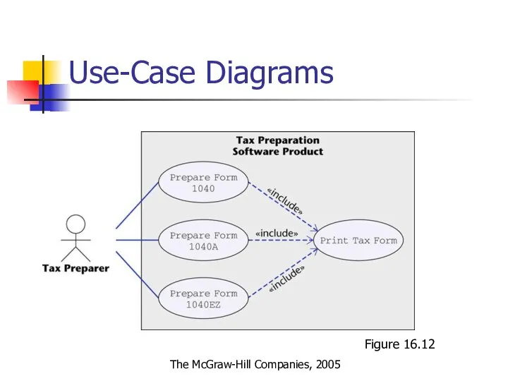
- 14. Use-Case Diagrams Extend: a dotted line labeled > with an arrow toward the base case. The
- 15. Use-Case Diagrams Figure 16.12 The McGraw-Hill Companies, 2005
- 16. Use-Case Diagrams Both Make Appointment and Request Medication include Check Patient Record as a subtask (include)
- 17. Class diagram A class diagram depicts classes and their interrelationships Used for describing structure and behavior
- 18. Class diagram Each class is represented by a rectangle subdivided into three compartments Name Attributes Operations
- 19. Class diagram
- 20. OO Relationships There are two kinds of Relationships Generalization (parent-child relationship) Association (student enrolls in course)
- 21. Subtype2 Supertype Subtype1 OO Relationships: Generalization -Inheritance is a required feature of object orientation -Generalization expresses
- 22. Represent relationship between instances of classes Student enrolls in a course Courses have students Courses have
- 23. Association: Multiplicity and Roles University Person 1 0..1 * * Multiplicity Symbol Meaning 1 One and
- 24. Class diagram [from UML Distilled Third Edition]
- 25. Association: Model to Implementation Class Student { Course enrolls[4]; } Class Course { Student have[]; }
- 26. OO Relationships: Composition Class W Class P1 Class P2 Association Models the part–whole relationship Composition Also
- 27. OO Relationships: Aggregation Class C Class E1 Class E2 AGGREGATION Container Class Containee Classes Bag Apples
- 28. Aggregation vs. Composition Composition is really a strong form of association components have only one owner
- 29. Good Practice: CRC Card Class Responsibility Collaborator easy to describe how classes work by moving cards
- 30. Interaction Diagrams show how objects interact with one another UML supports two types of interaction diagrams
- 31. Sequence Diagram(make a phone call) Caller Phone Recipient Picks up Dial tone Dial Ring notification Ring
- 32. Sequence Diagram:Object interaction Self-Call: A message that an Object sends to itself. Condition: indicates when a
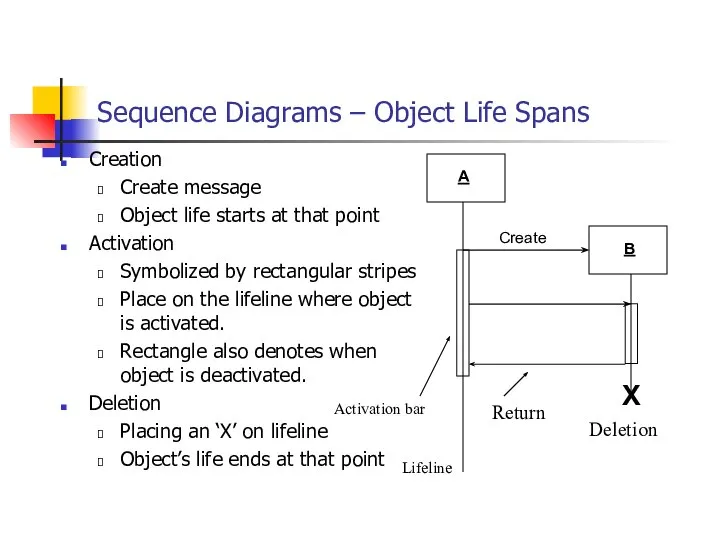
- 33. Sequence Diagrams – Object Life Spans Creation Create message Object life starts at that point Activation
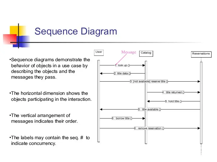
- 34. Sequence Diagram Sequence diagrams demonstrate the behavior of objects in a use case by describing the
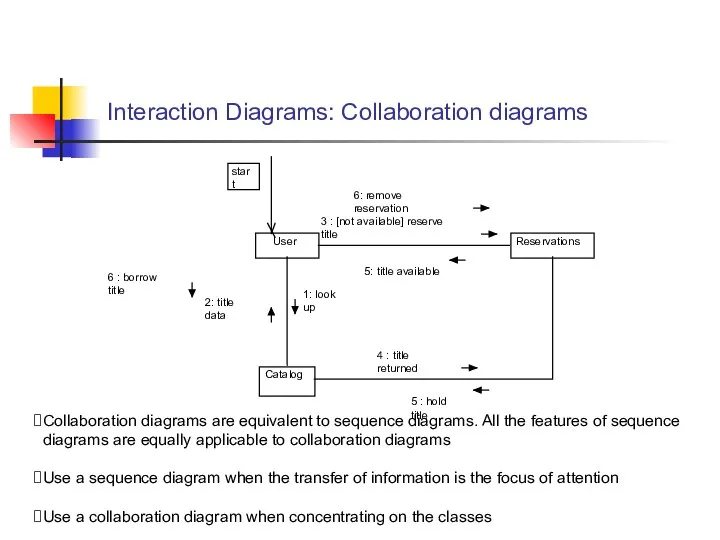
- 35. Interaction Diagrams: Collaboration diagrams User Catalog Reservations start 1: look up 2: title data 3 :
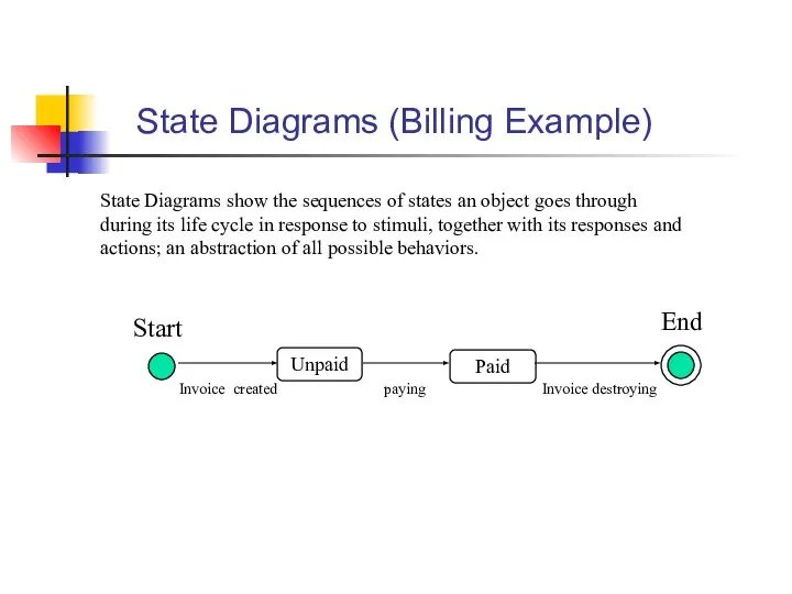
- 36. State Diagrams (Billing Example) State Diagrams show the sequences of states an object goes through during
- 37. State Diagrams (Traffic light example) Yellow Red Green Traffic Light State Transition Green timer expires Yellow
- 38. What UML Modeling tools we use today? List of UML tools http://en.wikipedia.org/wiki/List_of_UML_tools ArgoUML: http://argouml.tigris.org/ Rational Rose
- 39. Conclusion UML is a standardized specification language for object modeling Several UML diagrams: use-case diagram: a
- 41. Скачать презентацию
Слайд 2About myself
Yi Luo
TA for EEL5881
3rd Year Phd student in CpE
Email: [email protected]
Office hour:
About myself
Yi Luo
TA for EEL5881
3rd Year Phd student in CpE
Email: [email protected]
Office hour:

Слайд 3Acknowledgements
Slides material are taken from different sources including:
the slides of Mr. Shiyuan
Acknowledgements
Slides material are taken from different sources including:
the slides of Mr. Shiyuan
Слайд 4Outline
What is UML and why we use UML?
How to use UML diagrams
Outline
What is UML and why we use UML?
How to use UML diagrams
Слайд 5What is UML and Why we use UML?
UML → “Unified Modeling Language”
Language:
What is UML and Why we use UML?
UML → “Unified Modeling Language”
Language:
Слайд 6What is UML and Why we use UML?
More description about UML:
It is
What is UML and Why we use UML?
More description about UML:
It is
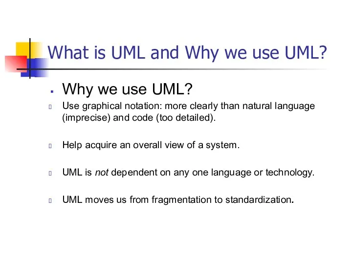
Слайд 7What is UML and Why we use UML?
Why we use UML?
Use graphical
What is UML and Why we use UML?
Why we use UML?
Use graphical
Слайд 8What is UML and Why we use UML?
What is UML and Why we use UML?
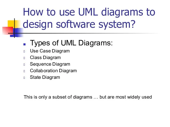
Слайд 9How to use UML diagrams to design software system?
Types of UML Diagrams:
Use
How to use UML diagrams to design software system?
Types of UML Diagrams:
Use
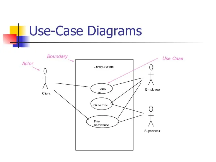
Слайд 10Use-Case Diagrams
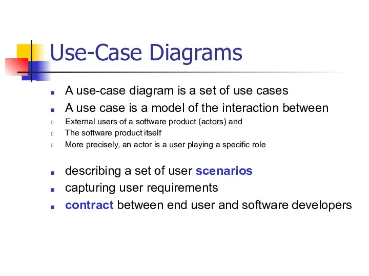
A use-case diagram is a set of use cases
A use case
Use-Case Diagrams
A use-case diagram is a set of use cases
A use case
Слайд 11Use-Case Diagrams
Library System
Borrow
Order Title
Fine Remittance
Client
Employee
Supervisor
Boundary
Actor
Use Case
Use-Case Diagrams
Library System
Borrow
Order Title
Fine Remittance
Client
Employee
Supervisor
Boundary
Actor
Use Case
Слайд 12
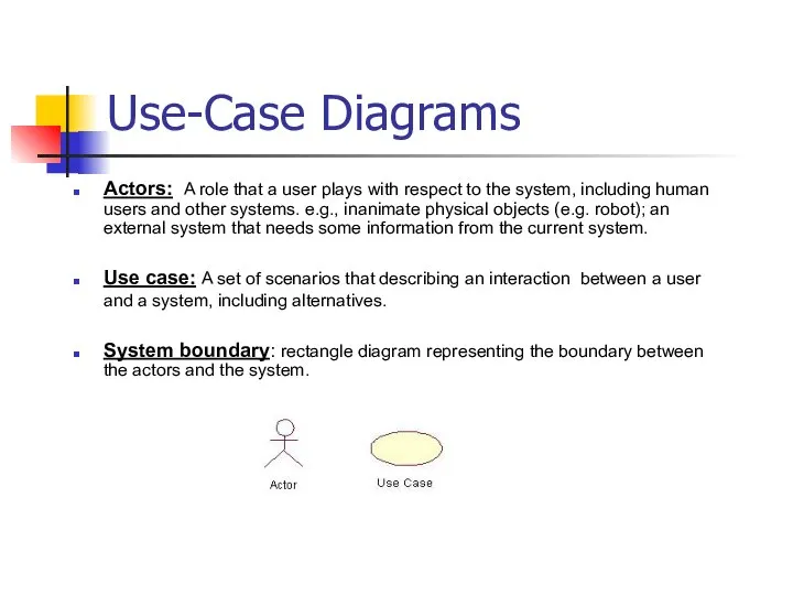
Use-Case Diagrams
Actors: A role that a user plays with respect to
Use-Case Diagrams
Actors: A role that a user plays with respect to
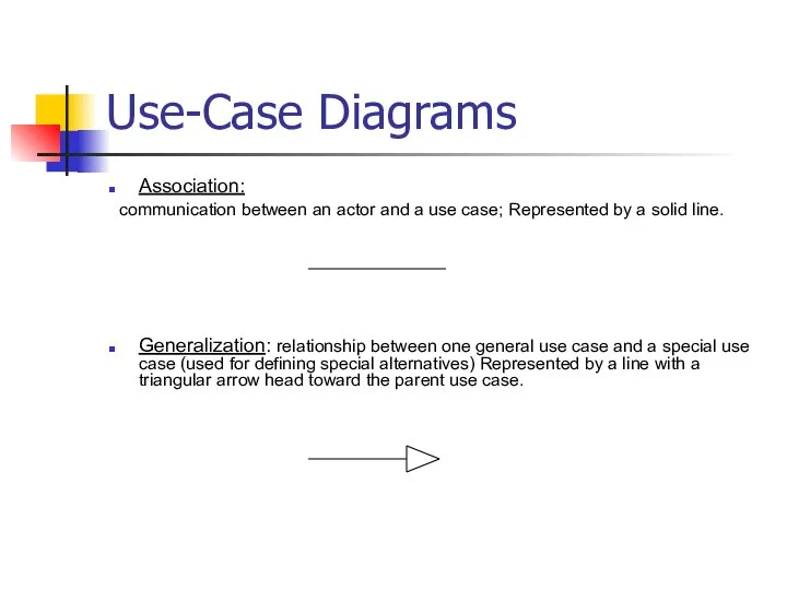
Слайд 13Use-Case Diagrams
Association:
communication between an actor and a use case; Represented
Use-Case Diagrams
Association:
communication between an actor and a use case; Represented
Слайд 14Use-Case Diagrams
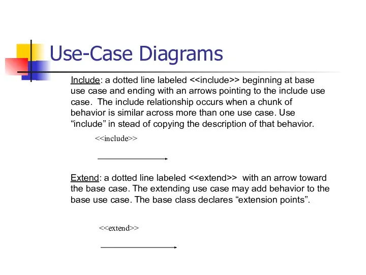
Extend: a dotted line labeled <> with an arrow toward the
Use-Case Diagrams
Extend: a dotted line labeled <
Слайд 15Use-Case Diagrams
Figure 16.12
The McGraw-Hill Companies, 2005
Use-Case Diagrams
Figure 16.12
The McGraw-Hill Companies, 2005
Слайд 16Use-Case Diagrams
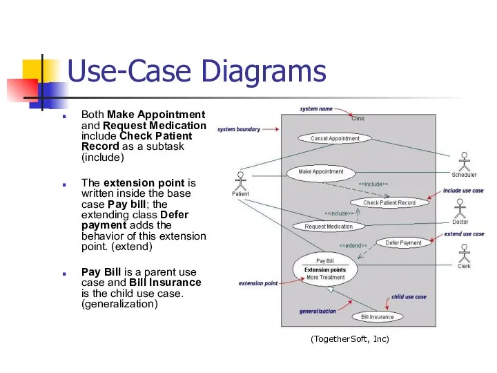
Both Make Appointment and Request Medication include Check Patient Record as
Use-Case Diagrams
Both Make Appointment and Request Medication include Check Patient Record as
Слайд 17Class diagram
A class diagram depicts classes and their interrelationships
Used for describing structure
Class diagram
A class diagram depicts classes and their interrelationships
Used for describing structure
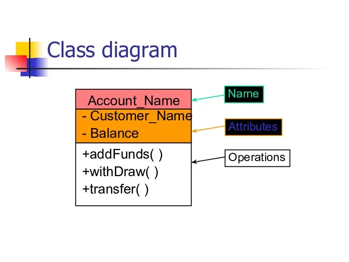
Слайд 18Class diagram
Each class is represented by a rectangle subdivided into three compartments
Name
Attributes
Operations
Modifiers
Class diagram
Each class is represented by a rectangle subdivided into three compartments
Name
Attributes
Operations
Modifiers
Слайд 19Class diagram
Class diagram
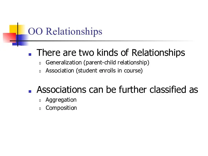
Слайд 20OO Relationships
There are two kinds of Relationships
Generalization (parent-child relationship)
Association (student enrolls in
OO Relationships
There are two kinds of Relationships
Generalization (parent-child relationship)
Association (student enrolls in
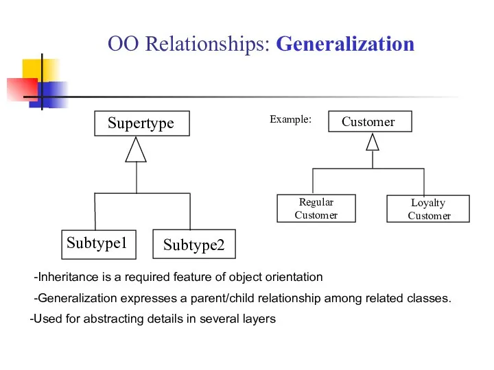
Слайд 21Subtype2
Supertype
Subtype1
OO Relationships: Generalization
-Inheritance is a required feature of object orientation
-Generalization expresses
Subtype2
Supertype
Subtype1
OO Relationships: Generalization
-Inheritance is a required feature of object orientation
-Generalization expresses
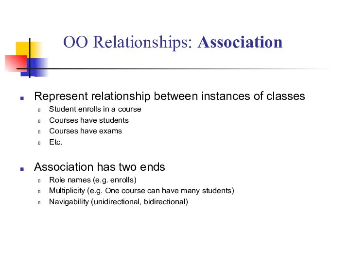
Слайд 22Represent relationship between instances of classes
Student enrolls in a course
Courses have students
Courses
Represent relationship between instances of classes
Student enrolls in a course
Courses have students
Courses
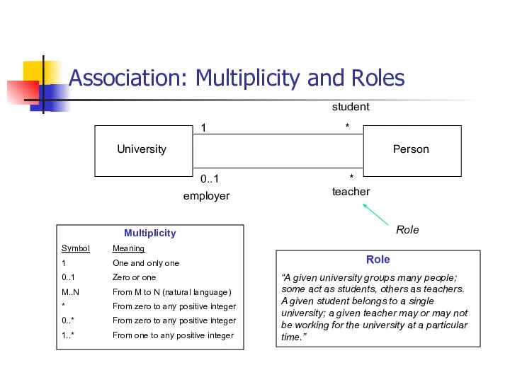
Слайд 23Association: Multiplicity and Roles
University
Person
1
0..1
*
*
Multiplicity
Symbol Meaning
1 One and only one
0..1 Zero or one
M..N From M to N
Association: Multiplicity and Roles
University
Person
1
0..1
*
*
Multiplicity
Symbol Meaning
1 One and only one
0..1 Zero or one
M..N From M to N
Слайд 24Class diagram
[from UML Distilled Third Edition]
Class diagram
[from UML Distilled Third Edition]
![Class diagram [from UML Distilled Third Edition]](/_ipx/f_webp&q_80&fit_contain&s_1440x1080/imagesDir/jpg/1115283/slide-23.jpg)
Слайд 25Association: Model to Implementation
Class Student {
Course enrolls[4];
}
Class Course {
Student have[];
}
Student
Course
enrolls
has
*
4
Association: Model to Implementation
Class Student {
Course enrolls[4];
}
Class Course {
Student have[];
}
Student
Course
enrolls
has
*
4
![Association: Model to Implementation Class Student { Course enrolls[4]; } Class Course](/_ipx/f_webp&q_80&fit_contain&s_1440x1080/imagesDir/jpg/1115283/slide-24.jpg)
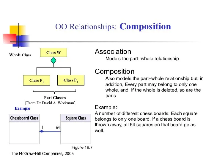
Слайд 26OO Relationships: Composition
Class W
Class P1
Class P2
Association
Models the part–whole relationship
Composition
Also models
OO Relationships: Composition
Class W
Class P1
Class P2
Association
Models the part–whole relationship
Composition
Also models
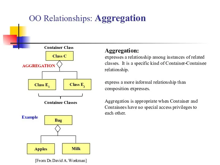
Слайд 27OO Relationships: Aggregation
Class C
Class E1
Class E2
AGGREGATION
Container Class
Containee Classes
Bag
Apples
Milk
Example
Aggregation:
expresses a
OO Relationships: Aggregation
Class C
Class E1
Class E2
AGGREGATION
Container Class
Containee Classes
Bag
Apples
Milk
Example
Aggregation:
expresses a
Слайд 28
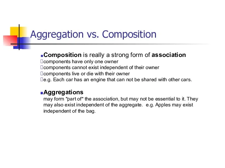
Aggregation vs. Composition
Composition is really a strong form of association
components have only
Aggregation vs. Composition
Composition is really a strong form of association
components have only
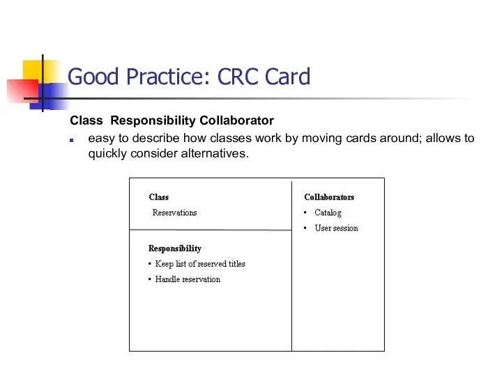
Слайд 29Good Practice: CRC Card
Class Responsibility Collaborator
easy to describe how classes work by
Good Practice: CRC Card
Class Responsibility Collaborator
easy to describe how classes work by
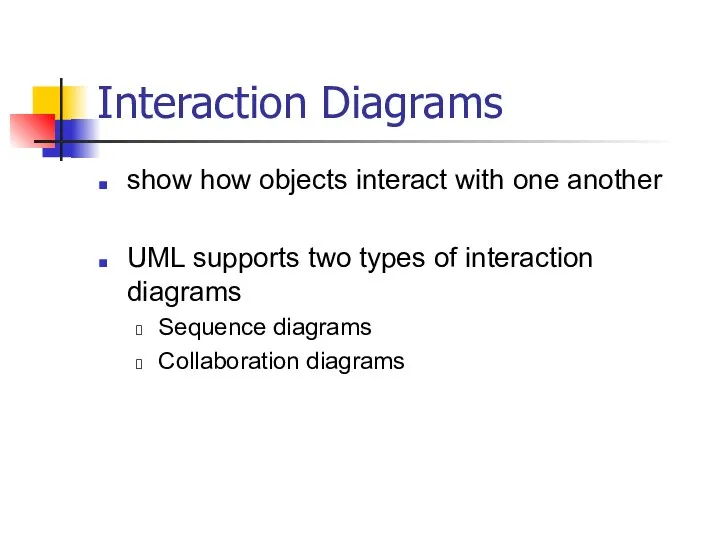
Слайд 30Interaction Diagrams
show how objects interact with one another
UML supports two types of
Interaction Diagrams
show how objects interact with one another
UML supports two types of
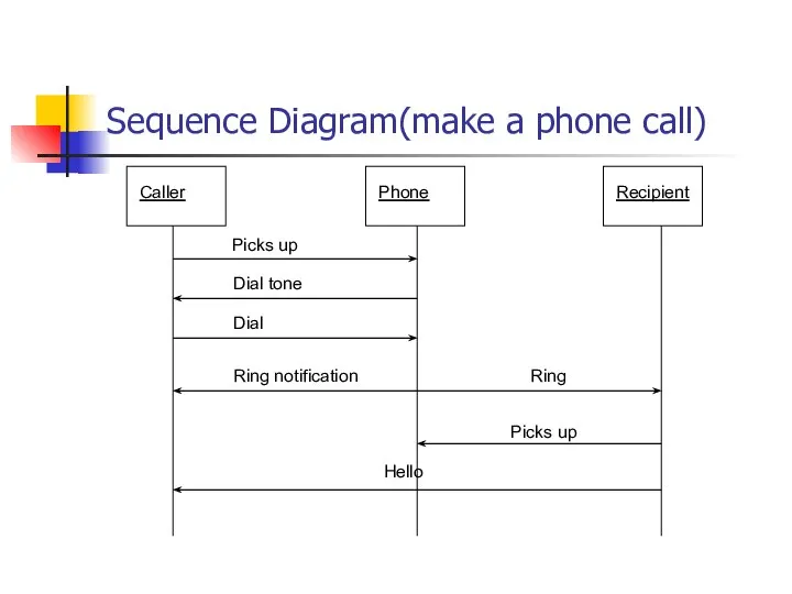
Слайд 31Sequence Diagram(make a phone call)
Caller
Phone
Recipient
Picks up
Dial tone
Dial
Ring notification
Ring
Picks up
Hello
Sequence Diagram(make a phone call)
Caller
Phone
Recipient
Picks up
Dial tone
Dial
Ring notification
Ring
Picks up
Hello
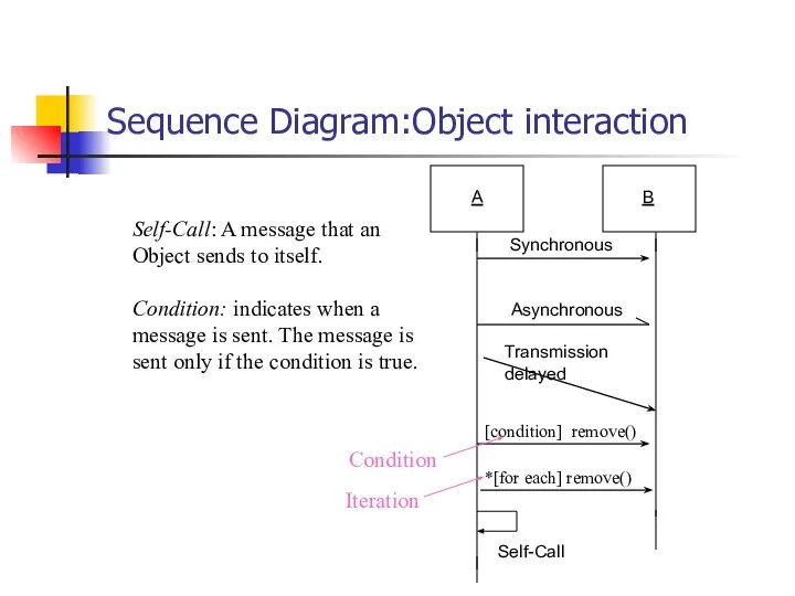
Слайд 32Sequence Diagram:Object interaction
Self-Call: A message that an
Object sends to itself.
Condition: indicates
Sequence Diagram:Object interaction
Self-Call: A message that an
Object sends to itself.
Condition: indicates
Слайд 33Sequence Diagrams – Object Life Spans
Creation
Create message
Object life starts at that point
Activation
Symbolized
Sequence Diagrams – Object Life Spans
Creation
Create message
Object life starts at that point
Activation
Symbolized
Слайд 34
Sequence Diagram
Sequence diagrams demonstrate the behavior of objects in a use case
Sequence Diagram
Sequence diagrams demonstrate the behavior of objects in a use case
Слайд 35
Interaction Diagrams: Collaboration diagrams
User
Catalog
Reservations
start
1: look up
2: title data
3 : [not available]
Interaction Diagrams: Collaboration diagrams
User
Catalog
Reservations
start
1: look up
2: title data
3 : [not available]
Слайд 36 State Diagrams (Billing Example)
State Diagrams show the sequences of states an
State Diagrams (Billing Example)
State Diagrams show the sequences of states an
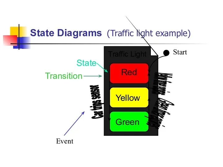
Слайд 37State Diagrams (Traffic light example)
Yellow
Red
Green
Traffic Light
State
Transition
Green timer expires
Yellow timer expires
Car trips sensor
State Diagrams (Traffic light example)
Yellow
Red
Green
Traffic Light
State
Transition
Green timer expires
Yellow timer expires
Car trips sensor
Слайд 38What UML Modeling tools we use today?
List of UML tools http://en.wikipedia.org/wiki/List_of_UML_tools
ArgoUML: http://argouml.tigris.org/
Rational
What UML Modeling tools we use today?
List of UML tools http://en.wikipedia.org/wiki/List_of_UML_tools
ArgoUML: http://argouml.tigris.org/
Rational
Слайд 39Conclusion
UML is a standardized specification language for object modeling
Several UML diagrams:
use-case diagram:
Conclusion
UML is a standardized specification language for object modeling
Several UML diagrams:
use-case diagram:
 Здоровый ребёнок-Здоровое будущее!!!
 Будь здоров, малыш!
 Мукополисахаридозы в практике педиатра
 Открытия и изобретения древних охотников
 Изучение факторов окружающей среды, влияющих на качество остроты зрения учащихся среднего звена
 Подготовка педагогических измерительных материалов по физике, используемых при аккредитации общеобразовательных учреждений
 Туры Фрирайд. Лужба. Поднебесные зубья
 Как построить удачную композицию для рисунка. Основы композиции
 Презентация на тему Поисковые системы интернета
 Таинство крещения
 Презентация на тему Урок развития речи по картине С. Григорьева "Вратарь". Описание действий
 Тульское лето 2020
 NutriNRG - натуральный энергетический напиток
 АВТОМАТИЗИРОВАННЫЙ УЧЕТ АРХИВНЫХ ДОКУМЕНТОВ
 Проект. Кто нас защищает
 Инструментальная транскоммуникация: мост между мирами
 Тема лекции:«Прикладная информатика в табличном процессоре»
 Русские ярмарки
 Особенности работы программы
 Компания Medical Icons
 Составление меню завтрака. Сервировка стола
 Коммуникационное агентство 22:22. Проекты
 Платежная система WebMoney Transfer. Статистика за 20012006 годы.
 Проверочная работа
 Средства массовой информации и анализ информационных программ
 Роль виртуального кабинета организаторов образования в развитии профессиональных компетенций
 Презентация на тему Окружающий мир 3 класс
  Установка для определения электротепловых параметров и характеристикмощных транзисторовMOSFET и IGBT