- Fundamental concepts of computer networks (chapter 1)

Содержание
- 2. Chapter 1 Fundamental concepts of computer networks. Lecture 1 1.
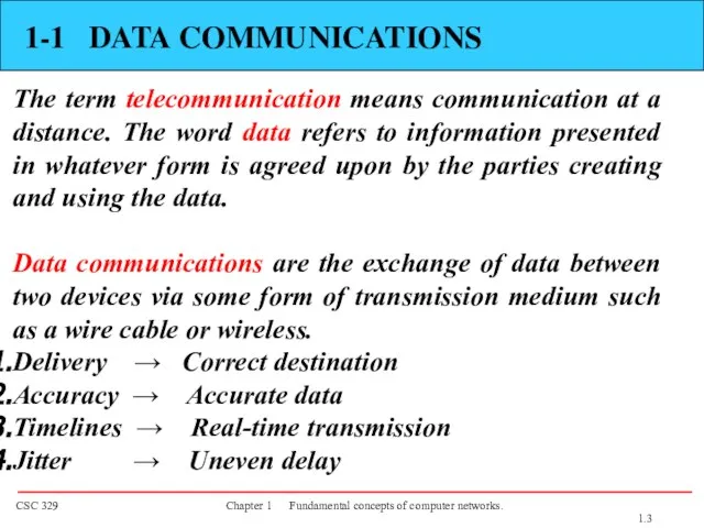
- 3. 1-1 DATA COMMUNICATIONS The term telecommunication means communication at a distance. The word data refers to
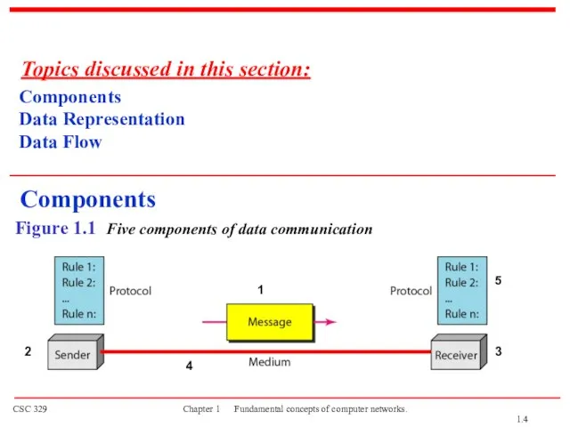
- 4. Figure 1.1 Five components of data communication Components Data Representation Data Flow Topics discussed in this
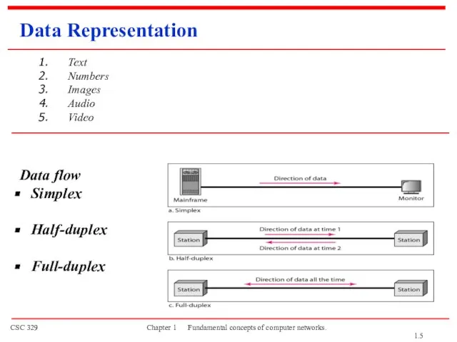
- 5. Data Representation Text Numbers Images Audio Video Data flow Simplex Half-duplex Full-duplex 1.
- 6. 1-2 NETWORKS A network is a set of devices (nodes) connected by communication links. A node
- 7. Types of connections Point to point A dedicated link is provided between two devices Multipoint More
- 8. Physical Topology Tree 1.
- 9. MESH Topology Every device has a dedicated point-to-point link to every other devices Dedicated Link carries
- 10. STAR Topology Each device has a dedicated point-to-point link only to a central controller, usually called
- 11. BUS Topology A multipoint topology All devices are linked through a backbone cable Nodes are connected
- 12. RING Topology Each device is dedicated point-to-point connection only with the two devices on either side
- 13. Tree Topology Advantages: Point-to-point wiring for individual segments. Supported by several hardware and software venders. Disadvantages:
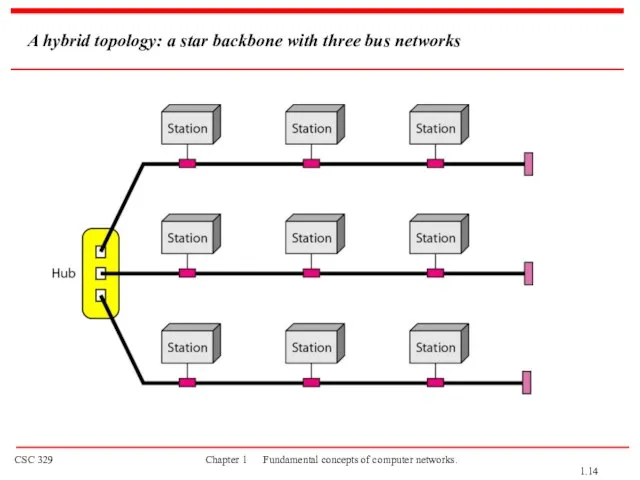
- 14. A hybrid topology: a star backbone with three bus networks 1.
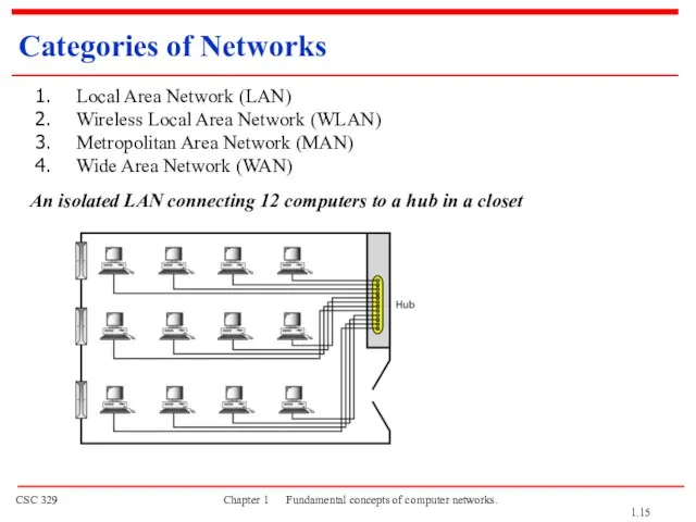
- 15. An isolated LAN connecting 12 computers to a hub in a closet Categories of Networks Local
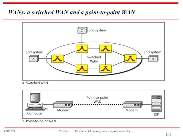
- 16. WANs: a switched WAN and a point-to-point WAN 1.
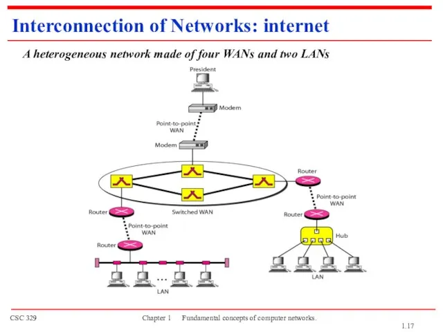
- 17. A heterogeneous network made of four WANs and two LANs Interconnection of Networks: internet 1.
- 18. 1-3 THE INTERNET The Internet has changed many aspects of our daily lives. It has affected
- 19. Hierarchical organization of the Internet 1.
- 20. 1-4 PROTOCOLS AND STANDARDS protocols and standards. Protocol is synonymous with rule. Standards are agreed-upon rules.
- 21. PROTOCOLS AND STANDARDS Protocols Syntax → format of the data Semantics → meaning of each section
- 22. PROTOCOLS AND STANDARDS Standards Organizations International Organization for Standardization (ISO) International Telecommunication Union - Telecommunication Standards
- 23. Lecture 2 OSI Model Network Models 1.
- 24. 1-5 LAYERED TASKS A network model is a layered architecture Task broken into subtasks Implemented separately
- 25. Tasks involved in sending a letter Sender, Receiver, and Carrier Hierarchy (services) Topics discussed in this
- 26. 1-5.1 THE OSI MODEL Established in 1947, the International Standards Organization (ISO) is a multinational body
- 27. ISO is the organization. OSI is the model. Layered Architecture Peer-to-Peer Processes Encapsulation Topics discussed in
- 28. Seven layers of the OSI model Layered Architecture Sender Receiver 1.
- 29. Layered Architecture A layered model Each layer performs a subset of the required communication functions Each
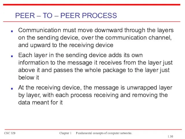
- 30. Communication must move downward through the layers on the sending device, over the communication channel, and
- 31. PEER – TO – PEER PROCESS The passing of the data and network information down through
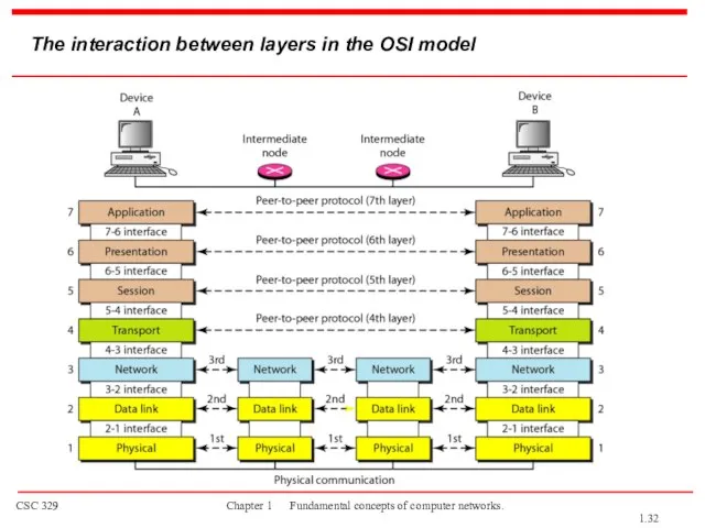
- 32. The interaction between layers in the OSI model 1.
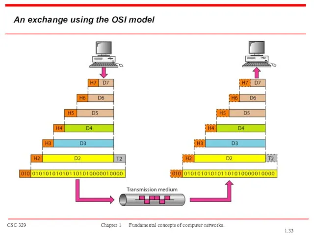
- 33. An exchange using the OSI model 1.
- 34. LAYERS IN THE OSI MODEL Physical Layer Data Link Layer Network Layer Transport Layer Session Layer
- 35. The physical layer is responsible for movements of individual bits from one hop (node) to the
- 36. Physical layer 1.
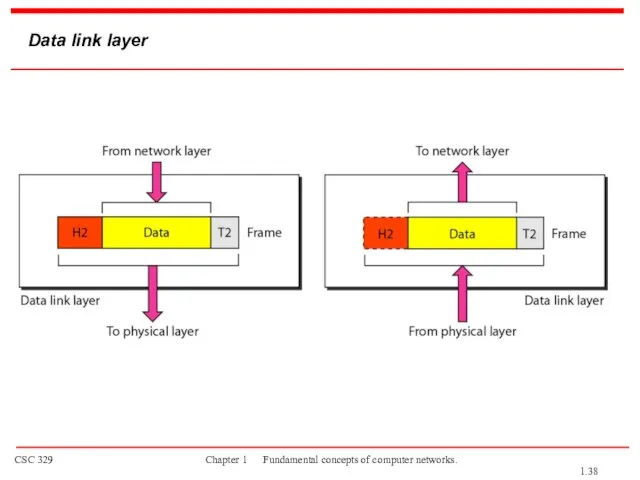
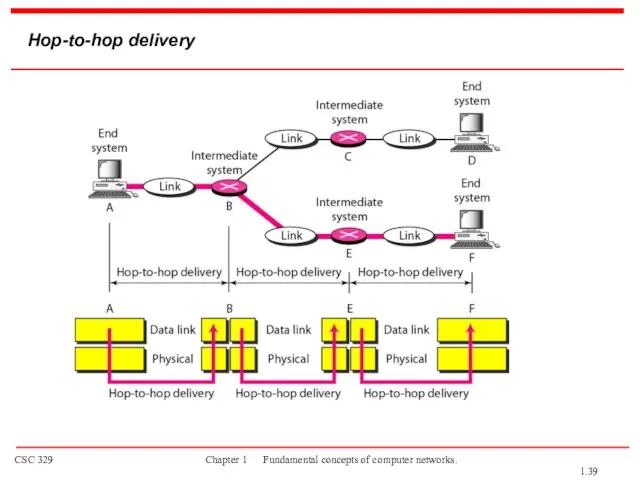
- 37. The data link layer is responsible for moving frames from one hop (node) to the next.
- 38. Data link layer 1.
- 39. Hop-to-hop delivery 1.
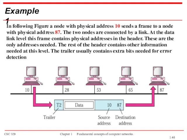
- 40. Example 1 In following Figure a node with physical address 10 sends a frame to a
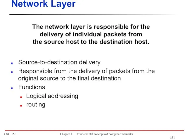
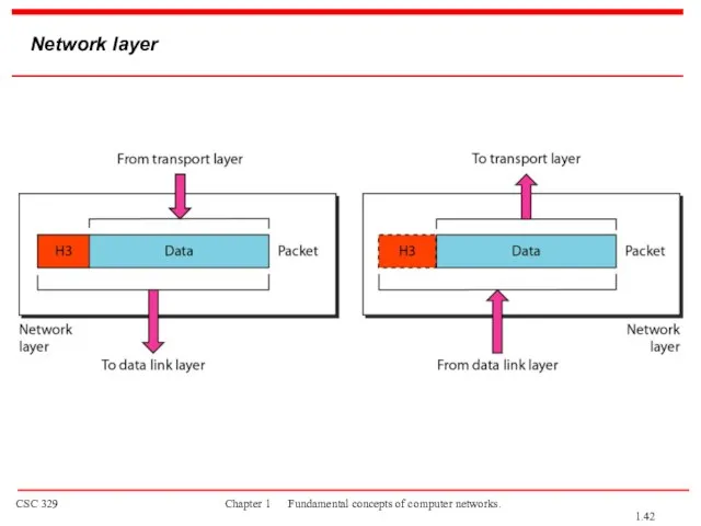
- 41. The network layer is responsible for the delivery of individual packets from the source host to
- 42. Network layer 1.
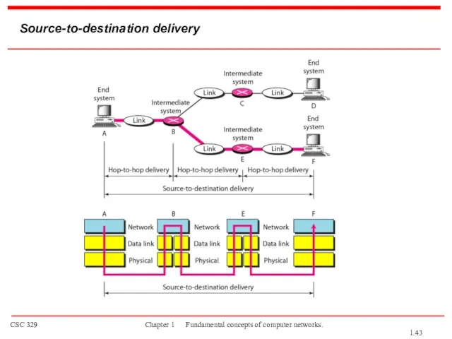
- 43. Source-to-destination delivery 1.
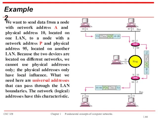
- 44. Example 2 We want to send data from a node with network address A and physical
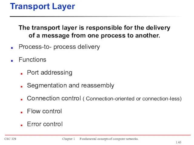
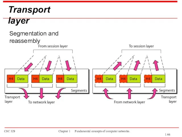
- 45. The transport layer is responsible for the delivery of a message from one process to another.
- 46. Transport layer Segmentation and reassembly 1.
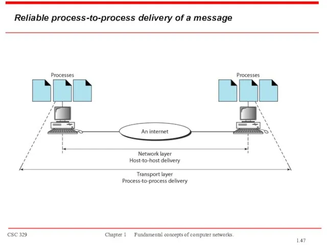
- 47. Reliable process-to-process delivery of a message 1.
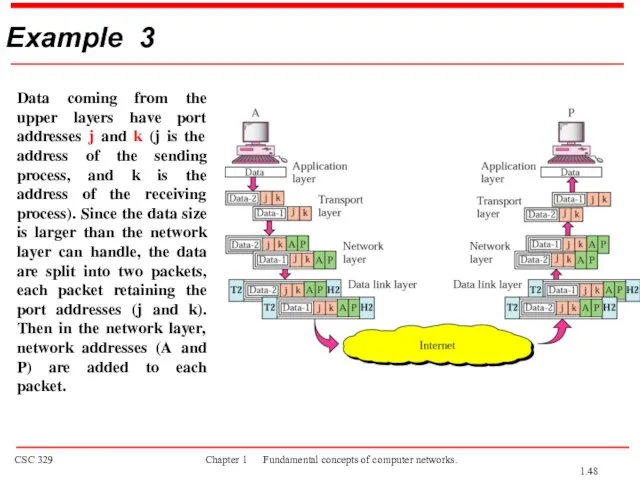
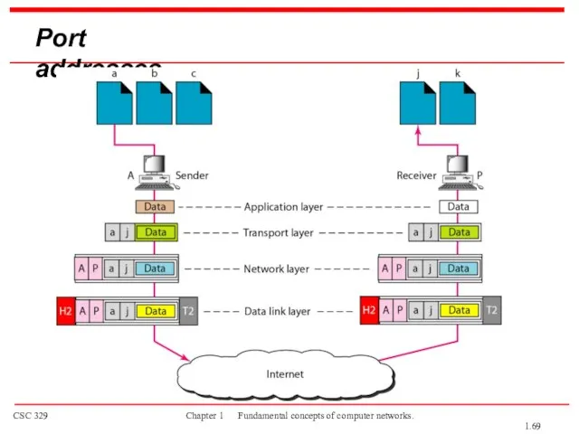
- 48. Example 3 Data coming from the upper layers have port addresses j and k (j is
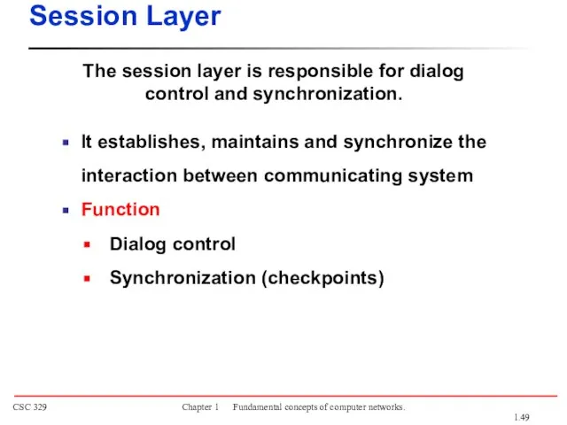
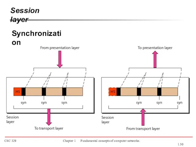
- 49. The session layer is responsible for dialog control and synchronization. Session Layer It establishes, maintains and
- 50. Session layer Synchronization 1.
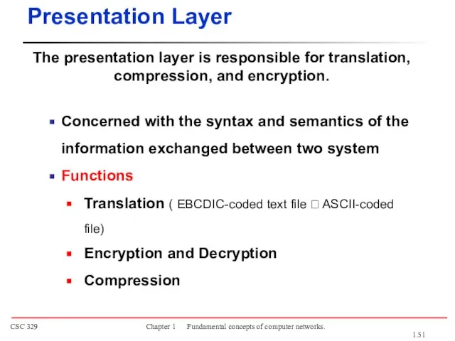
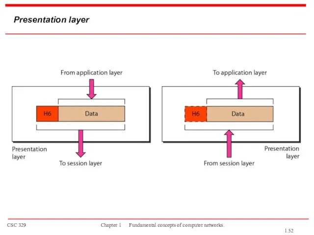
- 51. The presentation layer is responsible for translation, compression, and encryption. Presentation Layer Concerned with the syntax
- 52. Presentation layer 1.
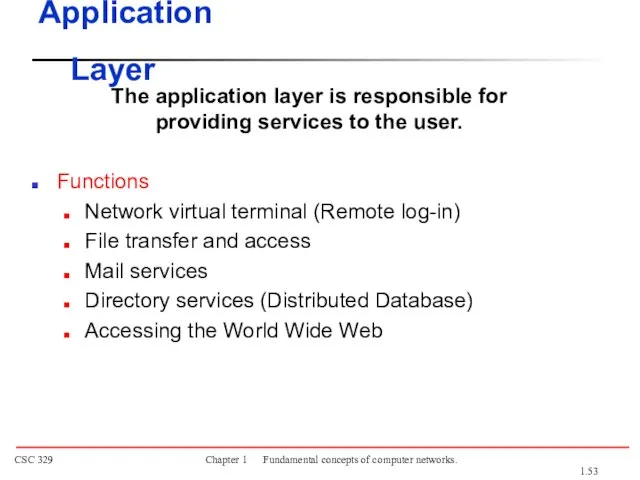
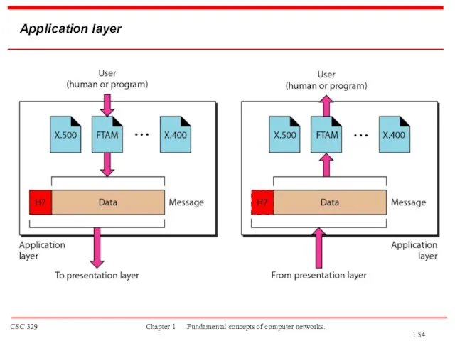
- 53. The application layer is responsible for providing services to the user. Functions Network virtual terminal (Remote
- 54. Application layer 1.
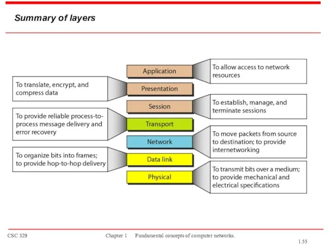
- 55. Summary of layers 1.
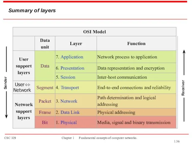
- 56. Summary of layers Sender Receiver 1.
- 57. Lecture 3 TCP/IP Model Network Models 1.
- 58. 1-5.2 TCP/IP PROTOCOL SUITE The layers in the TCP/IP protocol suite do not exactly match those
- 59. TCP/IP and OSI model OSI Model TCP/IP Model 1.
- 60. Internet Layer TCP/IP support the Internet Protocol IP ( unreliable). IP is a host-to-host protocol. Supporting
- 61. Transport Layer Process-to-process protocol. User Datagram Protocol (UDP) Transmission Control Protocol (TCP) Stream Control Transmission Protocol
- 62. 1-6 ADDRESSING Four levels of addresses are used in an internet employing the TCP/IP protocols: physical,
- 63. Addresses in TCP/IP 1.
- 64. Relationship of layers and addresses in TCP/IP 1.
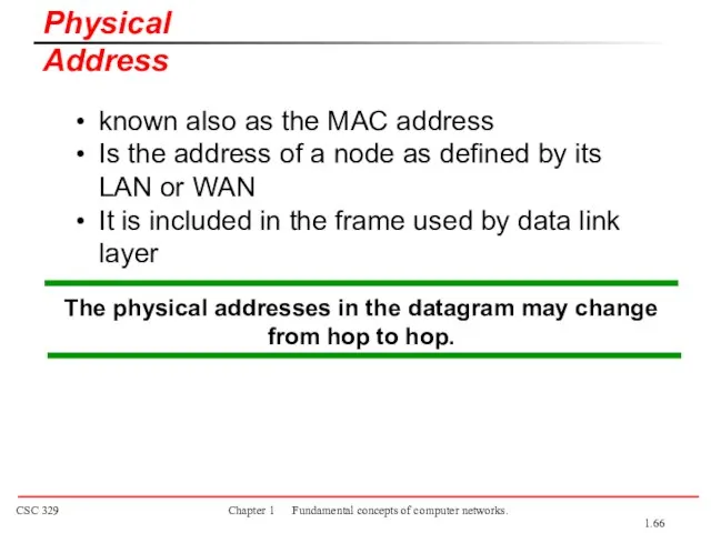
- 65. Physical addresses are imprinted on the NIC. Most local-area networks (Ethernet) use a 48-bit (6-byte) physical
- 66. The physical addresses in the datagram may change from hop to hop. known also as the
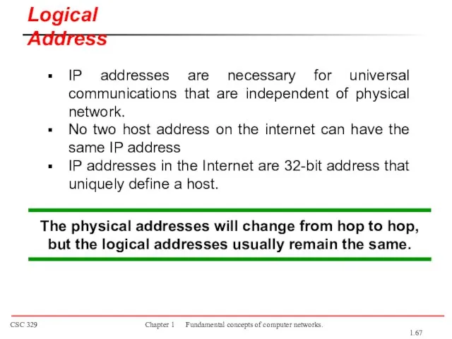
- 67. The physical addresses will change from hop to hop, but the logical addresses usually remain the
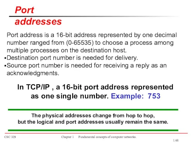
- 68. Port address is a 16-bit address represented by one decimal number ranged from (0-65535) to choose
- 69. Port addresses 1.
- 71. Скачать презентацию
Слайд 31-1 DATA COMMUNICATIONS
The term telecommunication means communication at a distance. The word
1-1 DATA COMMUNICATIONS
The term telecommunication means communication at a distance. The word
Слайд 4Figure 1.1 Five components of data communication
Components
Data Representation
Data Flow
Topics discussed in this
Figure 1.1 Five components of data communication
Components
Data Representation
Data Flow
Topics discussed in this
Слайд 5Data Representation
Text
Numbers
Images
Audio
Video
Data flow
Simplex
Half-duplex
Full-duplex
1.
Data Representation
Text
Numbers
Images
Audio
Video
Data flow
Simplex
Half-duplex
Full-duplex
1.
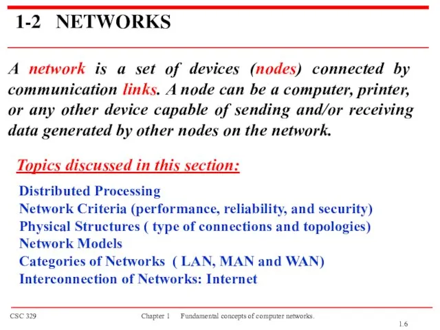
Слайд 61-2 NETWORKS
A network is a set of devices (nodes) connected by communication
1-2 NETWORKS
A network is a set of devices (nodes) connected by communication
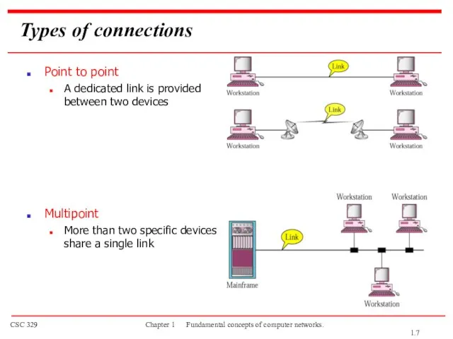
Слайд 7Types of connections
Point to point
A dedicated link is provided between two devices
Multipoint
More
Types of connections
Point to point
A dedicated link is provided between two devices
Multipoint
More
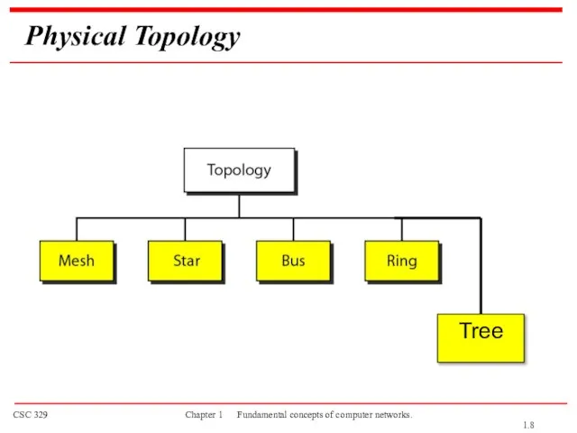
Слайд 8Physical Topology
Tree
1.
Physical Topology
Tree
1.
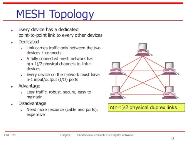
Слайд 9MESH Topology
Every device has a dedicated point-to-point link to every other devices
Dedicated
Link
MESH Topology
Every device has a dedicated point-to-point link to every other devices
Dedicated
Link
Слайд 10STAR Topology
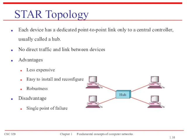
Each device has a dedicated point-to-point link only to a central
STAR Topology
Each device has a dedicated point-to-point link only to a central
Слайд 11BUS Topology
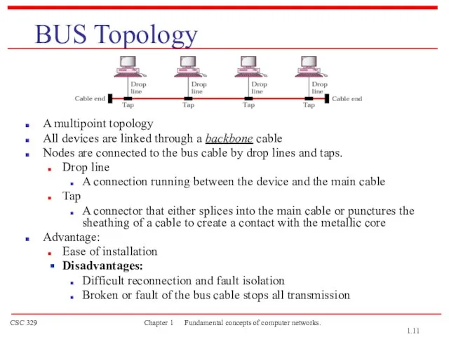
A multipoint topology
All devices are linked through a backbone cable
Nodes
BUS Topology
A multipoint topology
All devices are linked through a backbone cable
Nodes
Слайд 12RING Topology
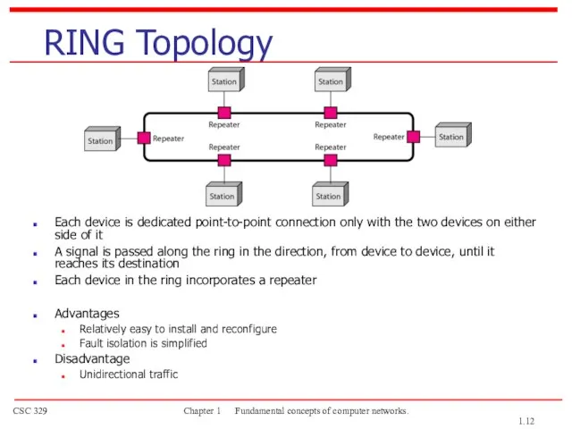
Each device is dedicated point-to-point connection only with the two devices
RING Topology
Each device is dedicated point-to-point connection only with the two devices
Слайд 13Tree Topology
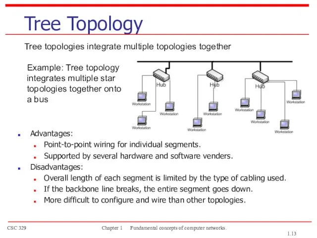
Advantages:
Point-to-point wiring for individual segments.
Supported by several hardware and
Tree Topology
Advantages:
Point-to-point wiring for individual segments.
Supported by several hardware and
Слайд 14A hybrid topology: a star backbone with three bus networks
1.
A hybrid topology: a star backbone with three bus networks
1.
Слайд 15An isolated LAN connecting 12 computers to a hub in a closet
Categories
An isolated LAN connecting 12 computers to a hub in a closet
Categories
Слайд 16WANs: a switched WAN and a point-to-point WAN
1.
WANs: a switched WAN and a point-to-point WAN
1.
Слайд 17A heterogeneous network made of four WANs and two LANs
Interconnection of Networks:
A heterogeneous network made of four WANs and two LANs
Interconnection of Networks:
Слайд 181-3 THE INTERNET
The Internet has changed many aspects of our daily lives.
1-3 THE INTERNET
The Internet has changed many aspects of our daily lives.
Слайд 19Hierarchical organization of the Internet
1.
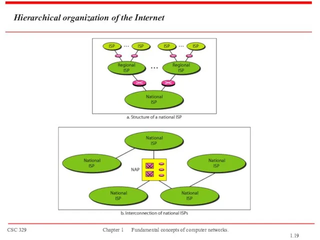
Hierarchical organization of the Internet
1.
Слайд 201-4 PROTOCOLS AND STANDARDS
protocols and standards.
Protocol is synonymous with rule.
Standards
1-4 PROTOCOLS AND STANDARDS
protocols and standards.
Protocol is synonymous with rule.
Standards
Слайд 21PROTOCOLS AND STANDARDS
Protocols
Syntax → format of the data
Semantics → meaning
PROTOCOLS AND STANDARDS
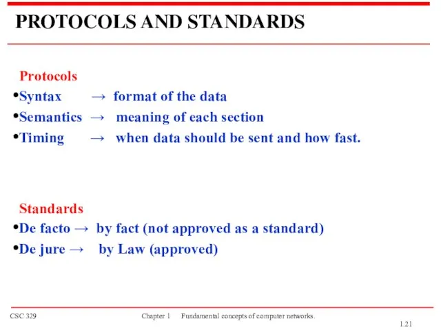
Protocols
Syntax → format of the data
Semantics → meaning
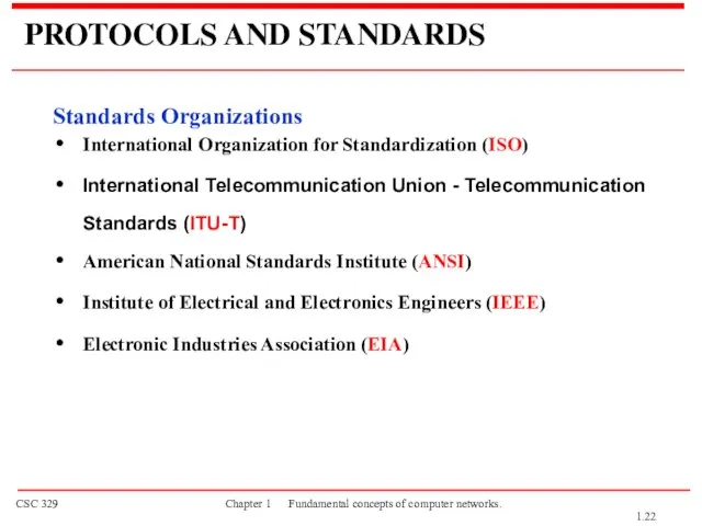
Слайд 22PROTOCOLS AND STANDARDS
Standards Organizations
International Organization for Standardization (ISO)
International Telecommunication Union -
PROTOCOLS AND STANDARDS
Standards Organizations
International Organization for Standardization (ISO)
International Telecommunication Union -
Слайд 23Lecture 2
OSI Model
Network Models
1.
Lecture 2
OSI Model
Network Models
1.
Слайд 241-5 LAYERED TASKS
A network model is a layered architecture
Task broken into subtasks
Implemented
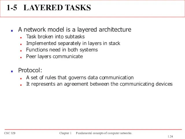
1-5 LAYERED TASKS
A network model is a layered architecture
Task broken into subtasks
Implemented
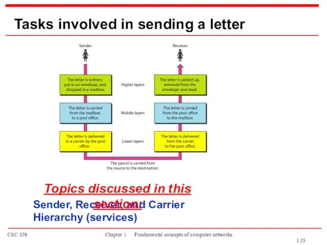
Слайд 25Tasks involved in sending a letter
Sender, Receiver, and Carrier
Hierarchy (services)
Topics discussed in
Tasks involved in sending a letter
Sender, Receiver, and Carrier
Hierarchy (services)
Topics discussed in
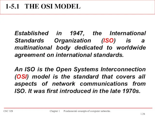
Слайд 261-5.1 THE OSI MODEL
Established in 1947, the International Standards Organization (ISO) is
1-5.1 THE OSI MODEL
Established in 1947, the International Standards Organization (ISO) is
Слайд 27ISO is the organization.
OSI is the model.
Layered Architecture
Peer-to-Peer Processes
Encapsulation
Topics discussed in this
ISO is the organization.
OSI is the model.
Layered Architecture
Peer-to-Peer Processes
Encapsulation
Topics discussed in this
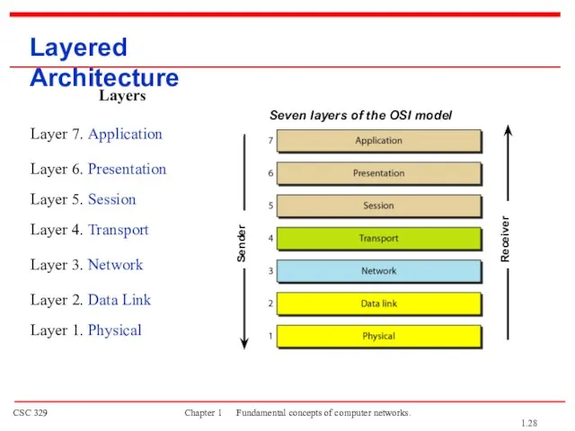
Слайд 28Seven layers of the OSI model
Layered Architecture
Sender
Receiver
1.
Seven layers of the OSI model
Layered Architecture
Sender
Receiver
1.
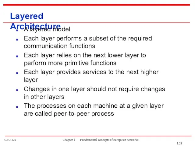
Слайд 29Layered Architecture
A layered model
Each layer performs a subset of the required communication
Layered Architecture
A layered model
Each layer performs a subset of the required communication
Слайд 30Communication must move downward through the layers on the sending device, over
Communication must move downward through the layers on the sending device, over
Слайд 31PEER – TO – PEER PROCESS
The passing of the data and network
PEER – TO – PEER PROCESS
The passing of the data and network
Слайд 32The interaction between layers in the OSI model
1.
The interaction between layers in the OSI model
1.
Слайд 33An exchange using the OSI model
1.
An exchange using the OSI model
1.
Слайд 34LAYERS IN THE OSI MODEL
Physical Layer
Data Link Layer
Network Layer
Transport Layer
Session Layer
Presentation Layer
Application
LAYERS IN THE OSI MODEL
Physical Layer
Data Link Layer
Network Layer
Transport Layer
Session Layer
Presentation Layer
Application
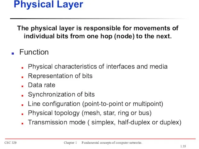
Слайд 35The physical layer is responsible for movements of
individual bits from one hop
The physical layer is responsible for movements of
individual bits from one hop
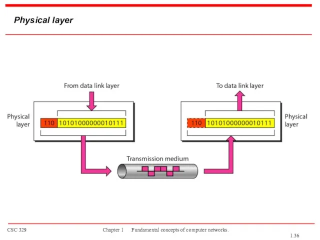
Слайд 36Physical layer
1.
Physical layer
1.
Слайд 37The data link layer is responsible for moving
frames from one hop
The data link layer is responsible for moving frames from one hop
Слайд 38Data link layer
1.
Data link layer
1.
Слайд 39Hop-to-hop delivery
1.
Hop-to-hop delivery
1.
Слайд 40Example 1
In following Figure a node with physical address 10 sends a
Example 1
In following Figure a node with physical address 10 sends a
Слайд 41The network layer is responsible for the
delivery of individual packets from
The network layer is responsible for the delivery of individual packets from
Слайд 42Network layer
1.
Network layer
1.
Слайд 43Source-to-destination delivery
1.
Source-to-destination delivery
1.
Слайд 44Example 2
We want to send data from a node with network address
Example 2
We want to send data from a node with network address
Слайд 45The transport layer is responsible for the delivery
of a message from
The transport layer is responsible for the delivery of a message from
Слайд 46Transport layer
Segmentation and reassembly
1.
Transport layer
Segmentation and reassembly
1.
Слайд 47Reliable process-to-process delivery of a message
1.
Reliable process-to-process delivery of a message
1.
Слайд 48Example 3
Data coming from the upper layers have port addresses j and
Example 3
Data coming from the upper layers have port addresses j and
Слайд 49The session layer is responsible for dialog
control and synchronization.
Session Layer
It establishes,
The session layer is responsible for dialog
control and synchronization.
Session Layer
It establishes,
Слайд 50Session layer
Synchronization
1.
Session layer
Synchronization
1.
Слайд 51The presentation layer is responsible for translation, compression, and encryption.
Presentation Layer
Concerned with
The presentation layer is responsible for translation, compression, and encryption.
Presentation Layer
Concerned with
Слайд 52Presentation layer
1.
Presentation layer
1.
Слайд 53The application layer is responsible for
providing services to the user.
Functions
Network virtual
The application layer is responsible for
providing services to the user.
Functions
Network virtual
Слайд 54Application layer
1.
Application layer
1.
Слайд 55Summary of layers
1.
Summary of layers
1.
Слайд 56Summary of layers
Sender
Receiver
1.
Summary of layers
Sender
Receiver
1.
Слайд 57Lecture 3
TCP/IP Model
Network Models
1.
Lecture 3
TCP/IP Model
Network Models
1.
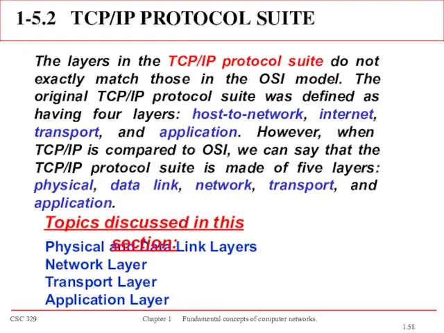
Слайд 581-5.2 TCP/IP PROTOCOL SUITE
The layers in the TCP/IP protocol suite do not
1-5.2 TCP/IP PROTOCOL SUITE
The layers in the TCP/IP protocol suite do not
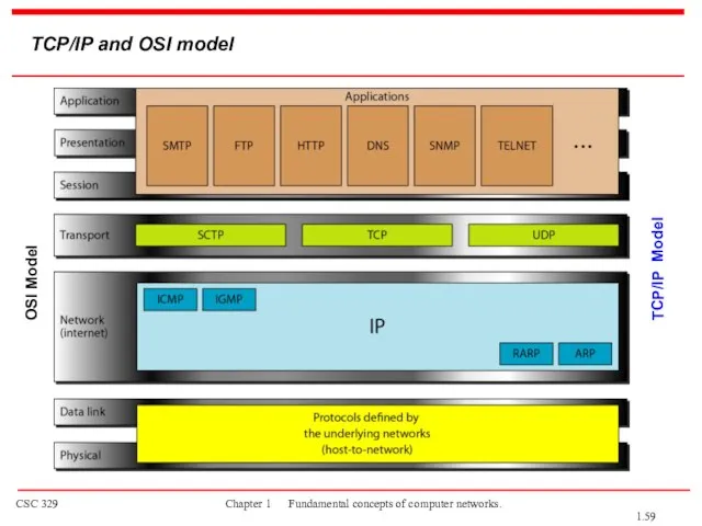
Слайд 59TCP/IP and OSI model
OSI Model
TCP/IP Model
1.
TCP/IP and OSI model
OSI Model
TCP/IP Model
1.
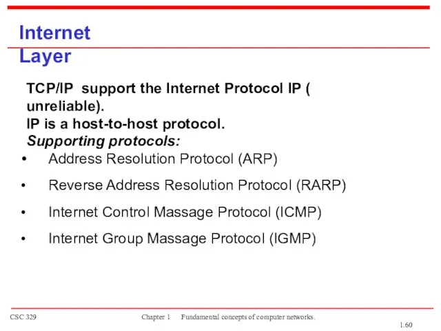
Слайд 60Internet Layer
TCP/IP support the Internet Protocol IP ( unreliable).
IP is a host-to-host
Internet Layer
TCP/IP support the Internet Protocol IP ( unreliable).
IP is a host-to-host
Слайд 61Transport Layer
Process-to-process protocol.
User Datagram Protocol (UDP)
Transmission Control Protocol (TCP)
Stream Control
Transport Layer
Process-to-process protocol.
User Datagram Protocol (UDP)
Transmission Control Protocol (TCP)
Stream Control
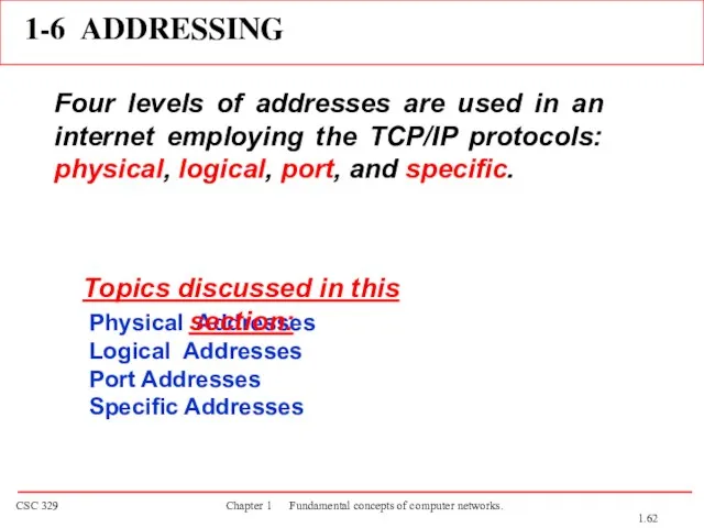
Слайд 621-6 ADDRESSING
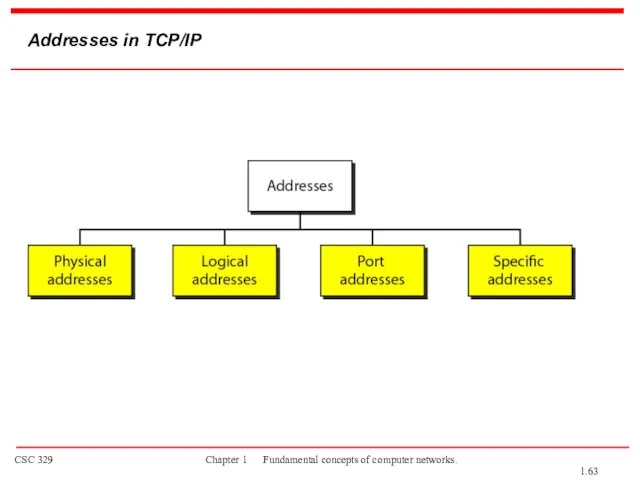
Four levels of addresses are used in an internet employing the
1-6 ADDRESSING
Four levels of addresses are used in an internet employing the
Слайд 63Addresses in TCP/IP
1.
Addresses in TCP/IP
1.
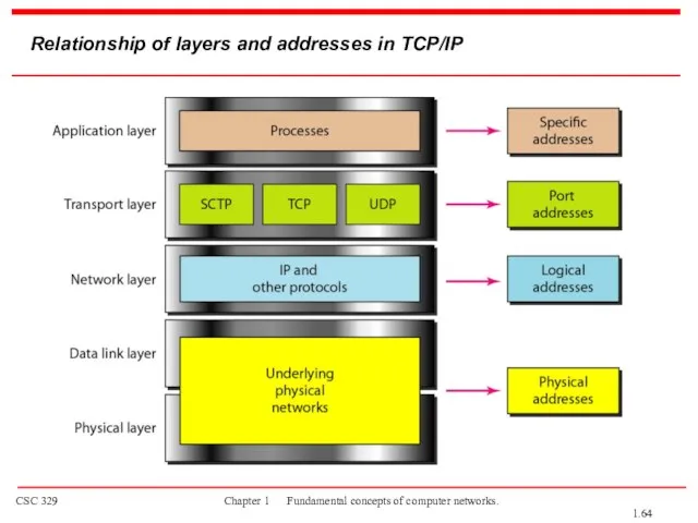
Слайд 64Relationship of layers and addresses in TCP/IP
1.
Relationship of layers and addresses in TCP/IP
1.
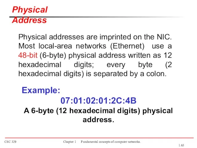
Слайд 65Physical addresses are imprinted on the NIC. Most local-area networks (Ethernet) use
Physical addresses are imprinted on the NIC. Most local-area networks (Ethernet) use
Слайд 66The physical addresses in the datagram may change from hop to hop.
known
The physical addresses in the datagram may change from hop to hop.
known
Слайд 67The physical addresses will change from hop to hop,
but the logical addresses
The physical addresses will change from hop to hop,
but the logical addresses
Слайд 68Port address is a 16-bit address represented by one decimal number ranged
Port address is a 16-bit address represented by one decimal number ranged
Слайд 69Port addresses
1.
Port addresses
1.
 Логические законы
 Условия if/elif/else
 «Проблемы мотивации учебной деятельности на уроках информатики. Уровневая дифференциация" Учитель информатики МОУ «Основная
  2_Prakticheskaya_rabota
 Модернизация ИТ-инфраструктуры
 Текстовые документы и технологии их создания
 Архитектура компьютера с хранимой программой
 Информация и её свойства
 Герман Холлерит
 Триггеры. Применение
 Система поиска книг, фильмов и музыки
 О работе, программах и будущих работах
 Алгоритмизация и программирование
 Разработка и анализ информационной системы безопасности для систем управления производством
 Компьютер и его строение
 Элементы алгебры логики. Математические основы информатики
 Поисковые системы Internet. Информационно поисковая система Рамблер
 Операционная система
 Основные модели предоставления услуг облачных вычислений: Software as a Service (SaaS) (ПО как услуга)
 Проектирование компьютерной сети ПАО Сбербанк
 SMM – Social Media Marketing
 Использование медиапространства в целях повышения мотивации и эффективности воспитательной деятельности
 Биналардагы элмә такталар
 Правила игры с монстрами
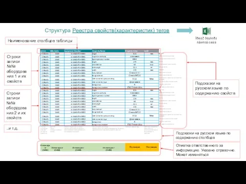 Реестры свойств тегов
 Электронды үкімет
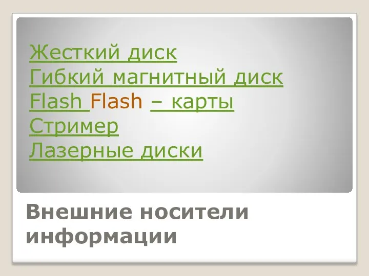 Внешние носители информации
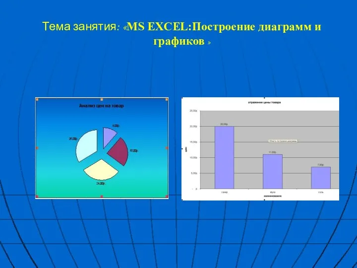 Ms Excel. Построение диаграмм и графиков