- 03 - System Specifications Rev B

Содержание
- 2. © 2001, Halliburton Energy Services, Inc. March 7, 2001 System Specifications What changes during the drilling
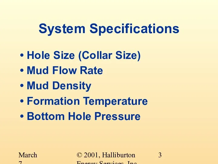
- 3. © 2001, Halliburton Energy Services, Inc. March 7, 2001 System Specifications Hole Size (Collar Size) Mud
- 4. © 2001, Halliburton Energy Services, Inc. March 7, 2001 System Specifications Hole Size Usually decreases with
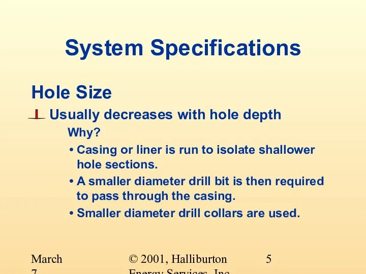
- 5. © 2001, Halliburton Energy Services, Inc. March 7, 2001 System Specifications Hole Size Usually decreases with
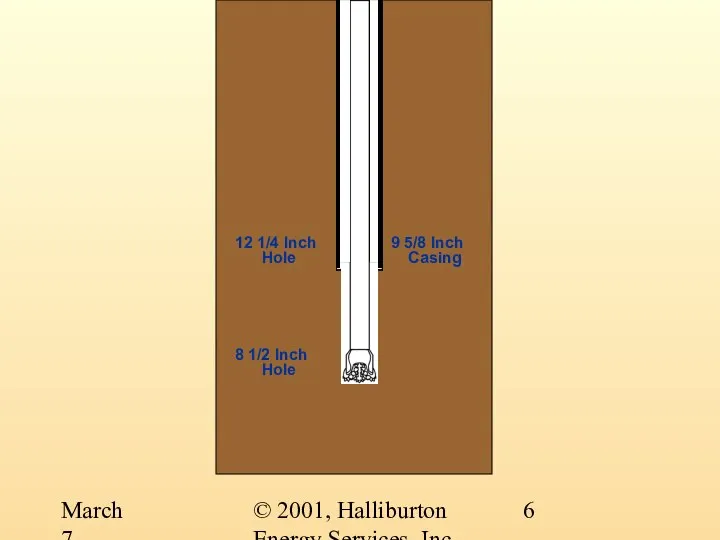
- 6. © 2001, Halliburton Energy Services, Inc. March 7, 2001 12 1/4 Inch Hole 9 5/8 Inch
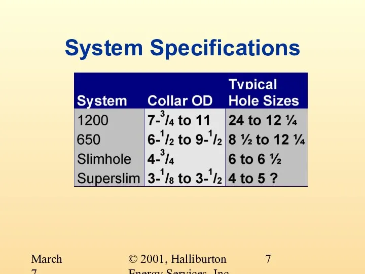
- 7. © 2001, Halliburton Energy Services, Inc. March 7, 2001 System Specifications
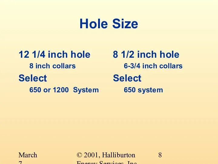
- 8. © 2001, Halliburton Energy Services, Inc. March 7, 2001 Hole Size 12 1/4 inch hole 8
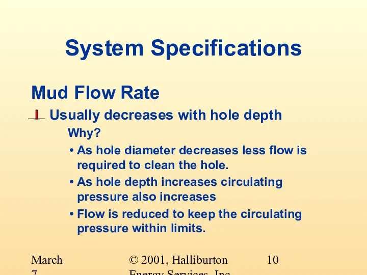
- 9. © 2001, Halliburton Energy Services, Inc. March 7, 2001 System Specifications Mud Flow Rate Usually decreases
- 10. © 2001, Halliburton Energy Services, Inc. March 7, 2001 System Specifications Mud Flow Rate Usually decreases
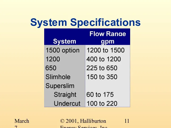
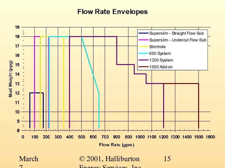
- 11. © 2001, Halliburton Energy Services, Inc. March 7, 2001 System Specifications
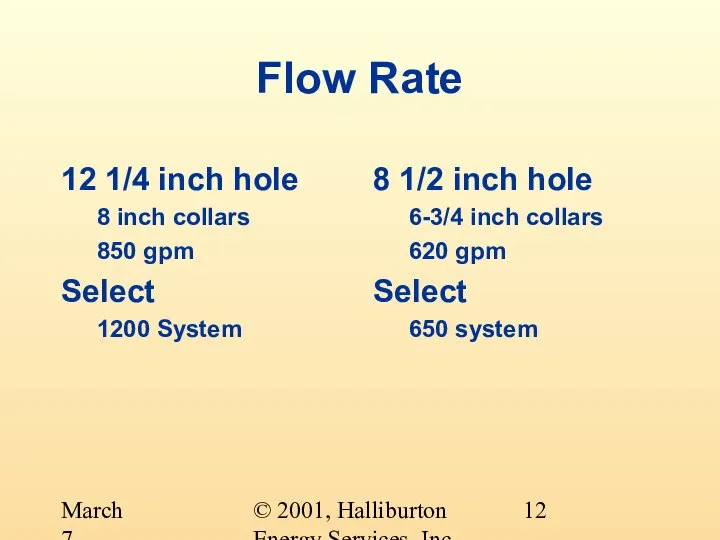
- 12. © 2001, Halliburton Energy Services, Inc. March 7, 2001 Flow Rate 12 1/4 inch hole 8
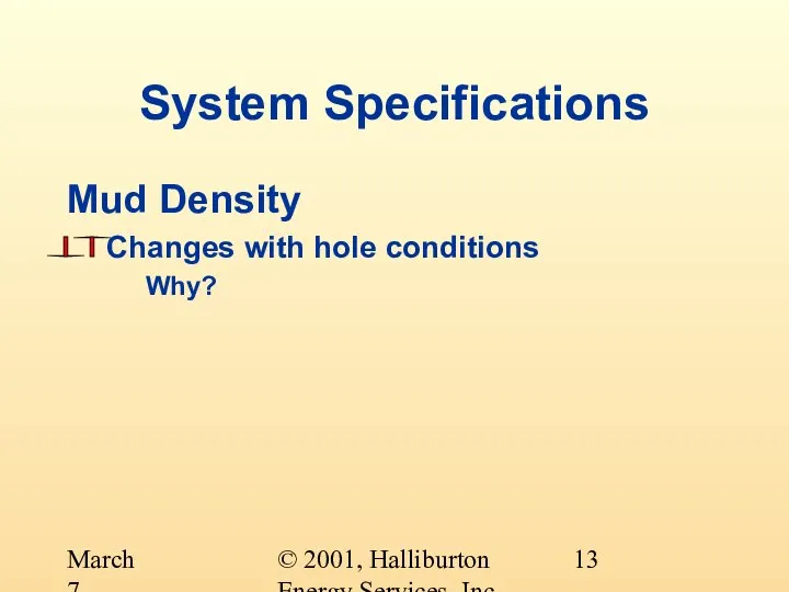
- 13. © 2001, Halliburton Energy Services, Inc. March 7, 2001 System Specifications Mud Density Changes with hole
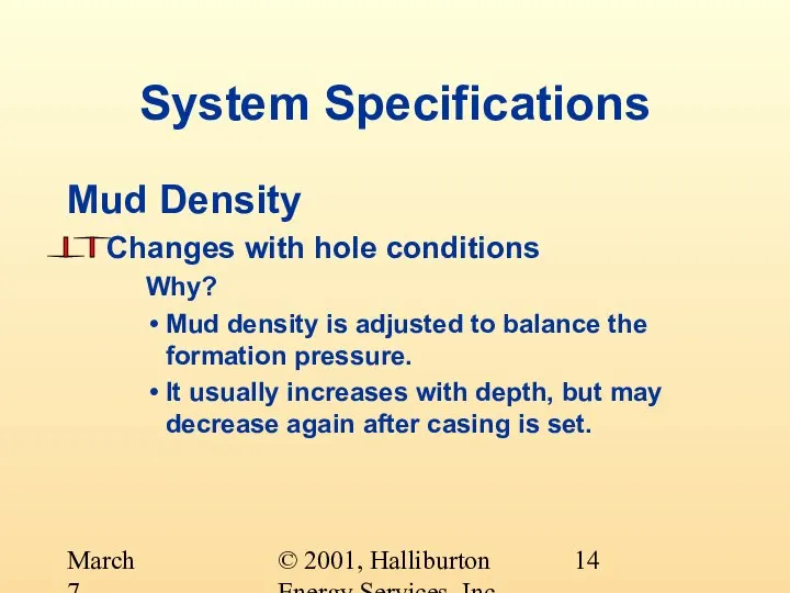
- 14. © 2001, Halliburton Energy Services, Inc. March 7, 2001 System Specifications Mud Density Changes with hole
- 15. © 2001, Halliburton Energy Services, Inc. March 7, 2001
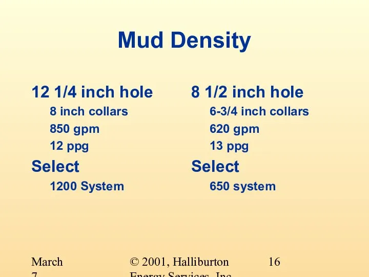
- 16. © 2001, Halliburton Energy Services, Inc. March 7, 2001 Mud Density 12 1/4 inch hole 8
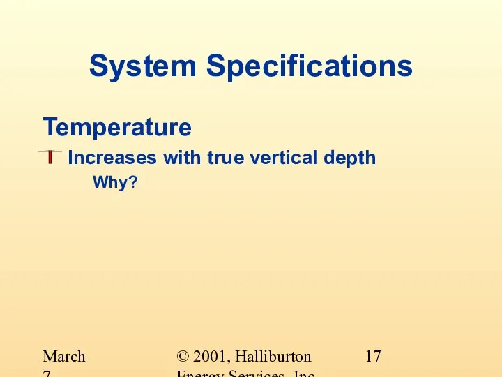
- 17. © 2001, Halliburton Energy Services, Inc. March 7, 2001 System Specifications Temperature Increases with true vertical
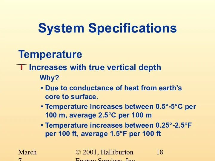
- 18. © 2001, Halliburton Energy Services, Inc. March 7, 2001 System Specifications Temperature Increases with true vertical
- 19. © 2001, Halliburton Energy Services, Inc. March 7, 2001 System Specifications Temperature Affects the selection of:
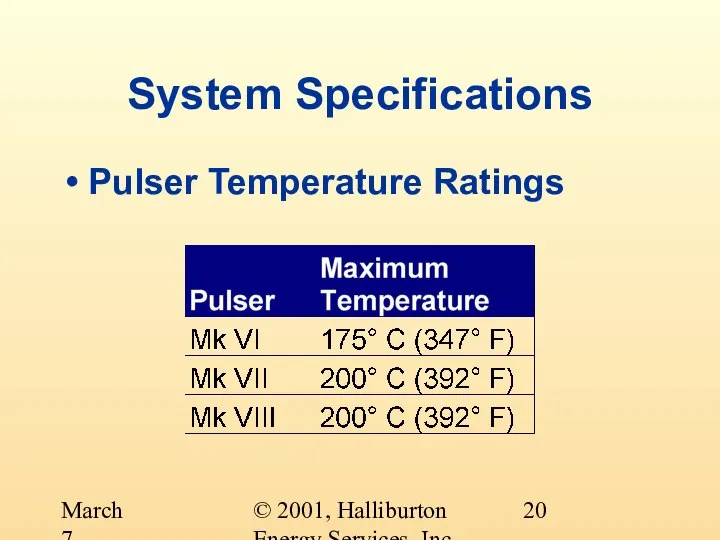
- 20. © 2001, Halliburton Energy Services, Inc. March 7, 2001 System Specifications Pulser Temperature Ratings
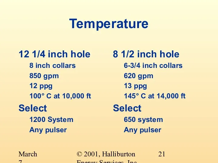
- 21. © 2001, Halliburton Energy Services, Inc. March 7, 2001 Temperature 12 1/4 inch hole 8 inch
- 22. © 2001, Halliburton Energy Services, Inc. March 7, 2001 System Specifications Temperature Affects the selection of:
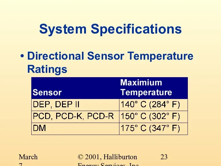
- 23. © 2001, Halliburton Energy Services, Inc. March 7, 2001 System Specifications Directional Sensor Temperature Ratings
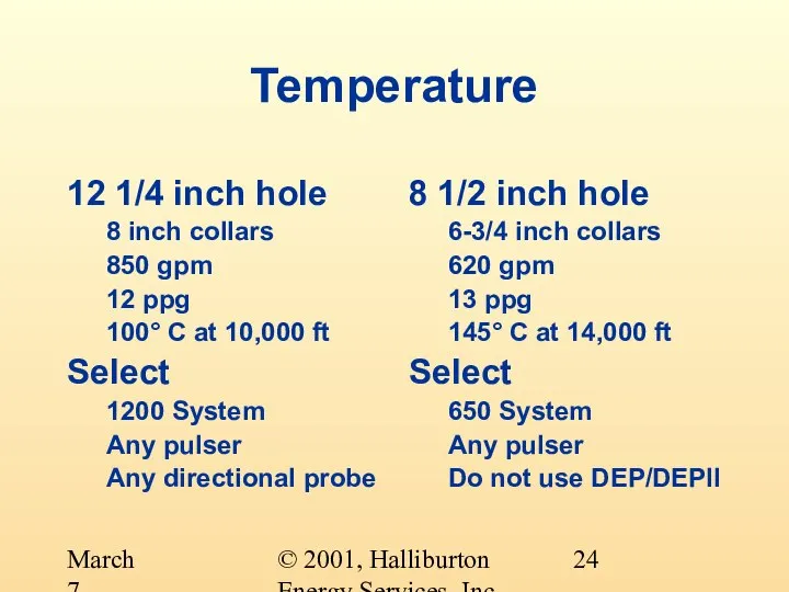
- 24. © 2001, Halliburton Energy Services, Inc. March 7, 2001 Temperature 12 1/4 inch hole 8 inch
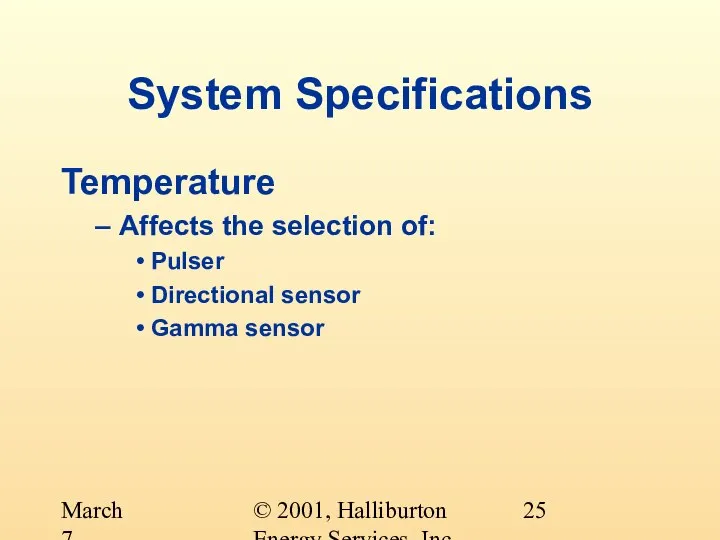
- 25. © 2001, Halliburton Energy Services, Inc. March 7, 2001 System Specifications Temperature Affects the selection of:
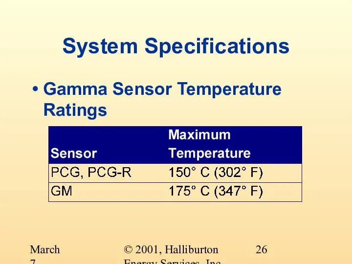
- 26. © 2001, Halliburton Energy Services, Inc. March 7, 2001 System Specifications Gamma Sensor Temperature Ratings
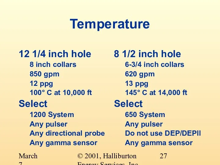
- 27. © 2001, Halliburton Energy Services, Inc. March 7, 2001 Temperature 12 1/4 inch hole 8 inch
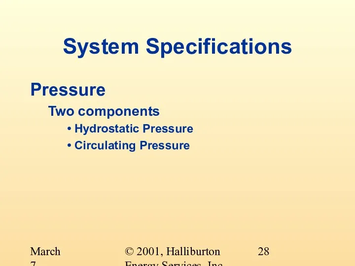
- 28. © 2001, Halliburton Energy Services, Inc. March 7, 2001 System Specifications Pressure Two components Hydrostatic Pressure
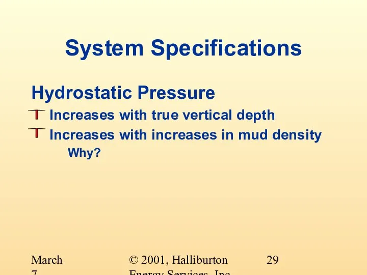
- 29. © 2001, Halliburton Energy Services, Inc. March 7, 2001 System Specifications Hydrostatic Pressure Increases with true
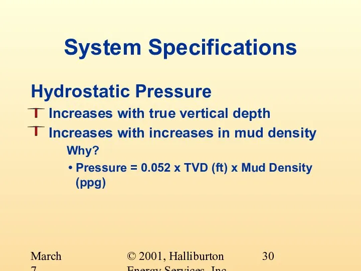
- 30. © 2001, Halliburton Energy Services, Inc. March 7, 2001 System Specifications Hydrostatic Pressure Increases with true
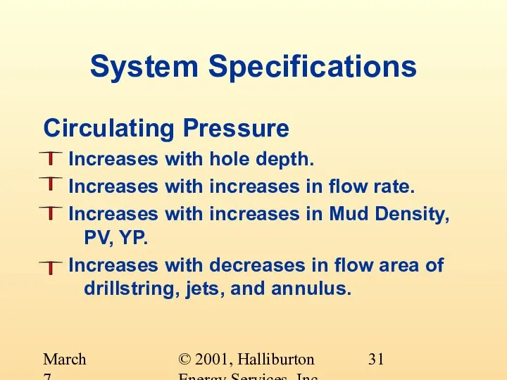
- 31. © 2001, Halliburton Energy Services, Inc. March 7, 2001 System Specifications Circulating Pressure Increases with hole
- 32. © 2001, Halliburton Energy Services, Inc. March 7, 2001 System Specifications Pressure What pressure is the
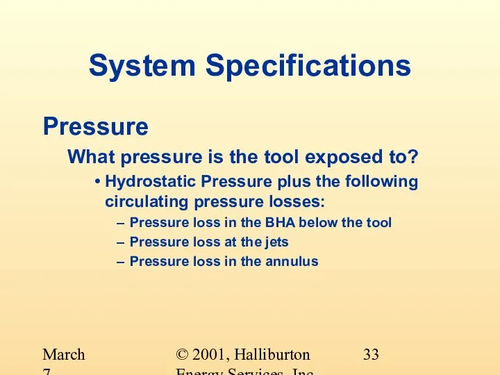
- 33. © 2001, Halliburton Energy Services, Inc. March 7, 2001 System Specifications Pressure What pressure is the
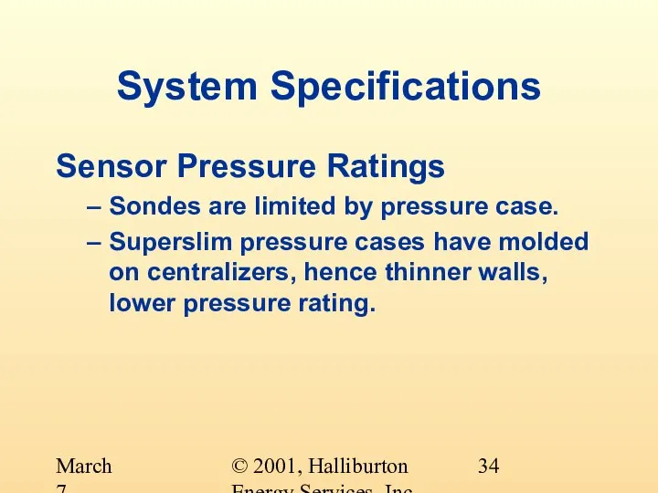
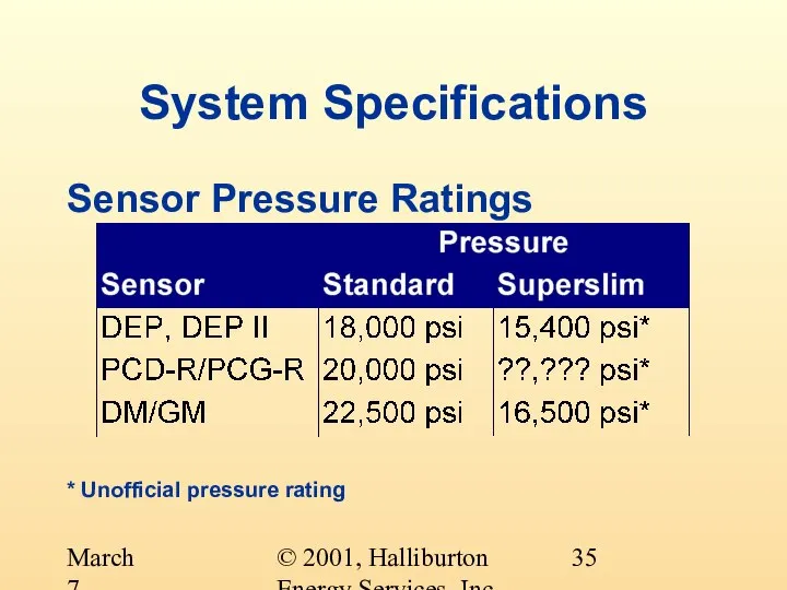
- 34. © 2001, Halliburton Energy Services, Inc. March 7, 2001 System Specifications Sensor Pressure Ratings Sondes are
- 35. © 2001, Halliburton Energy Services, Inc. March 7, 2001 Sensor Pressure Ratings * Unofficial pressure rating
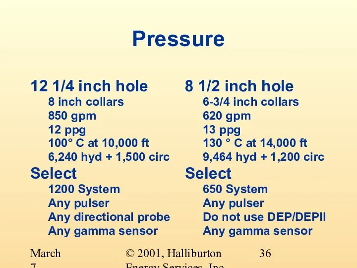
- 36. © 2001, Halliburton Energy Services, Inc. March 7, 2001 Pressure 12 1/4 inch hole 8 inch
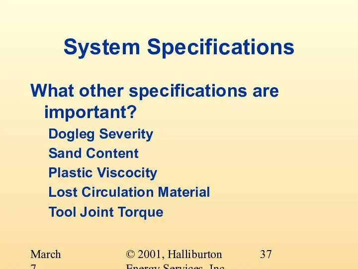
- 37. © 2001, Halliburton Energy Services, Inc. March 7, 2001 System Specifications What other specifications are important?
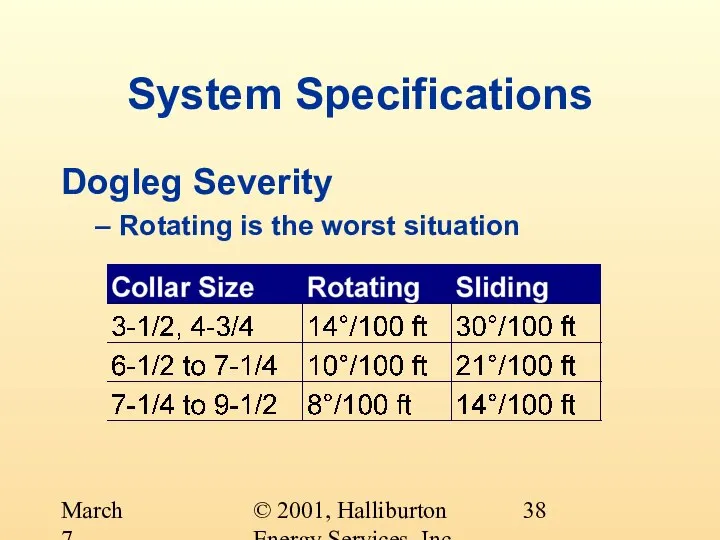
- 38. © 2001, Halliburton Energy Services, Inc. March 7, 2001 System Specifications Dogleg Severity Rotating is the
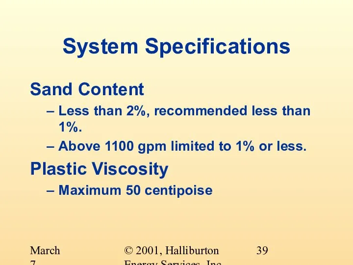
- 39. © 2001, Halliburton Energy Services, Inc. March 7, 2001 System Specifications Sand Content Less than 2%,
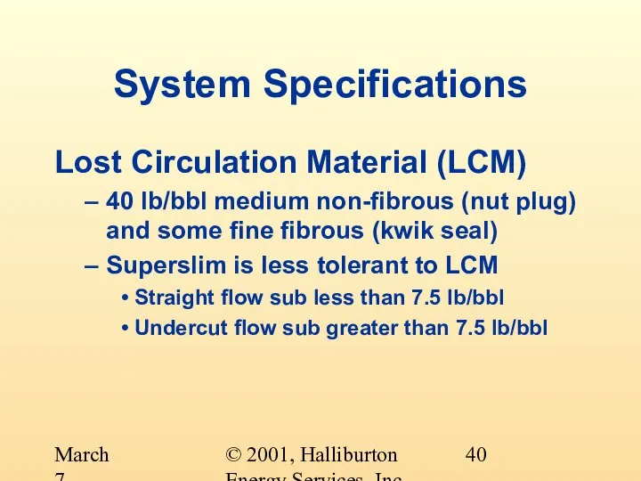
- 40. © 2001, Halliburton Energy Services, Inc. March 7, 2001 System Specifications Lost Circulation Material (LCM) 40
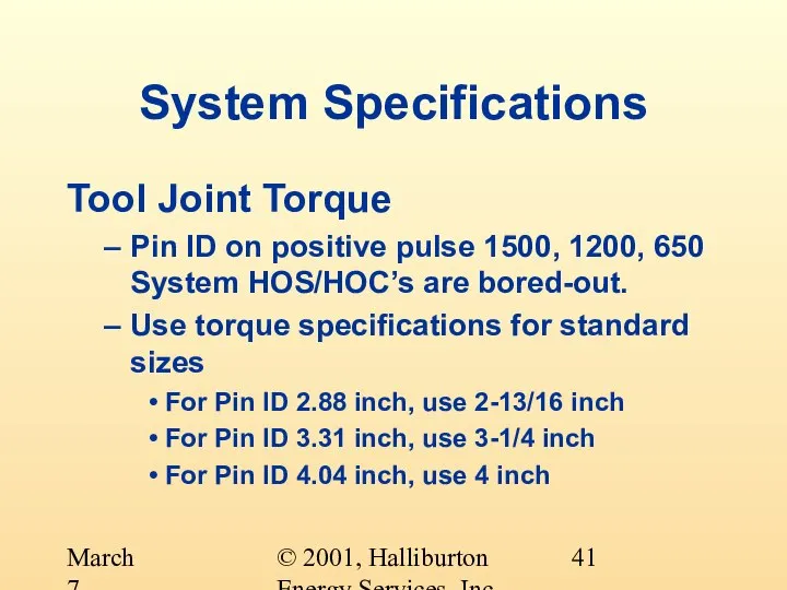
- 41. © 2001, Halliburton Energy Services, Inc. March 7, 2001 System Specifications Tool Joint Torque Pin ID
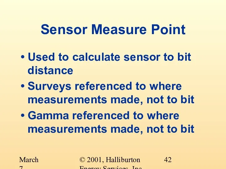
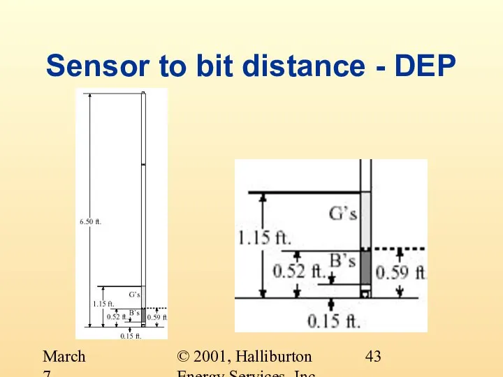
- 42. © 2001, Halliburton Energy Services, Inc. March 7, 2001 Sensor Measure Point Used to calculate sensor
- 43. © 2001, Halliburton Energy Services, Inc. March 7, 2001 Sensor to bit distance - DEP
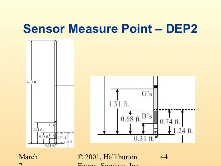
- 44. © 2001, Halliburton Energy Services, Inc. March 7, 2001 Sensor Measure Point – DEP2
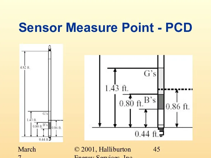
- 45. © 2001, Halliburton Energy Services, Inc. March 7, 2001 Sensor Measure Point - PCD
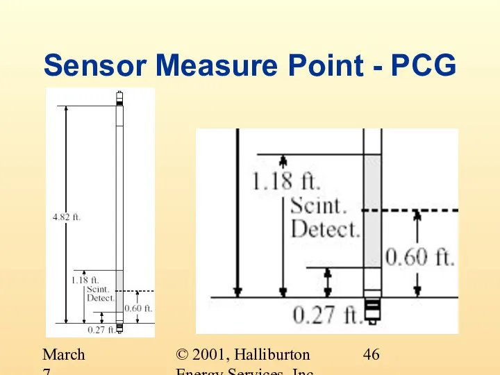
- 46. © 2001, Halliburton Energy Services, Inc. March 7, 2001 Sensor Measure Point - PCG
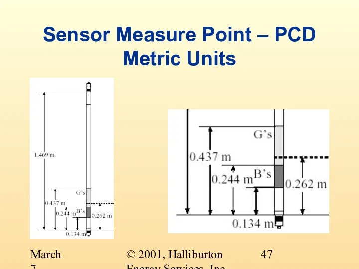
- 47. © 2001, Halliburton Energy Services, Inc. March 7, 2001 Sensor Measure Point – PCD Metric Units
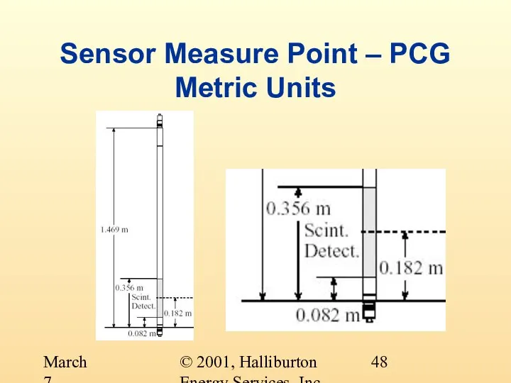
- 48. © 2001, Halliburton Energy Services, Inc. March 7, 2001 Sensor Measure Point – PCG Metric Units
- 49. © 2001, Halliburton Energy Services, Inc. March 7, 2001 System Specifications Tool Joint Torque How do
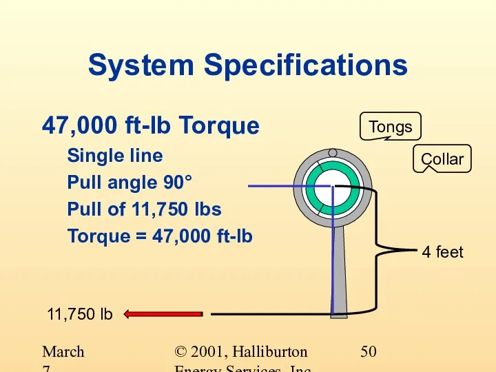
- 50. © 2001, Halliburton Energy Services, Inc. March 7, 2001 System Specifications 47,000 ft-lb Torque Single line
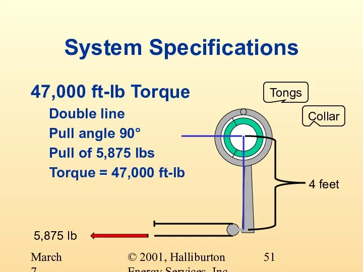
- 51. © 2001, Halliburton Energy Services, Inc. March 7, 2001 System Specifications 47,000 ft-lb Torque Double line
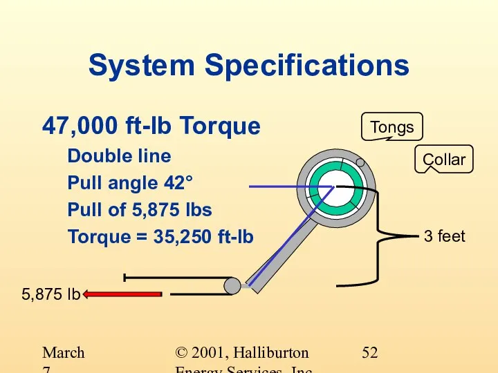
- 52. © 2001, Halliburton Energy Services, Inc. March 7, 2001 System Specifications 47,000 ft-lb Torque Double line
- 54. Скачать презентацию
Слайд 2© 2001, Halliburton Energy Services, Inc.
March 7, 2001
System Specifications
What changes during the
© 2001, Halliburton Energy Services, Inc.
March 7, 2001
System Specifications
What changes during the
Слайд 3© 2001, Halliburton Energy Services, Inc.
March 7, 2001
System Specifications
Hole Size (Collar Size)
Mud
© 2001, Halliburton Energy Services, Inc.
March 7, 2001
System Specifications
Hole Size (Collar Size)
Mud
Слайд 4© 2001, Halliburton Energy Services, Inc.
March 7, 2001
System Specifications
Hole Size
Usually decreases with
© 2001, Halliburton Energy Services, Inc.
March 7, 2001
System Specifications
Hole Size
Usually decreases with
Слайд 5© 2001, Halliburton Energy Services, Inc.
March 7, 2001
System Specifications
Hole Size
Usually decreases with
© 2001, Halliburton Energy Services, Inc.
March 7, 2001
System Specifications
Hole Size
Usually decreases with
Слайд 6© 2001, Halliburton Energy Services, Inc.
March 7, 2001
12 1/4 Inch
Hole
9 5/8 Inch
Casing
8
© 2001, Halliburton Energy Services, Inc.
March 7, 2001
12 1/4 Inch
Hole
9 5/8 Inch
Casing
8
Слайд 7© 2001, Halliburton Energy Services, Inc.
March 7, 2001
System Specifications
© 2001, Halliburton Energy Services, Inc.
March 7, 2001
System Specifications
Слайд 8© 2001, Halliburton Energy Services, Inc.
March 7, 2001
Hole Size
12 1/4 inch hole
8
© 2001, Halliburton Energy Services, Inc.
March 7, 2001
Hole Size
12 1/4 inch hole
8
Слайд 9© 2001, Halliburton Energy Services, Inc.
March 7, 2001
System Specifications
Mud Flow Rate
Usually decreases
© 2001, Halliburton Energy Services, Inc.
March 7, 2001
System Specifications
Mud Flow Rate
Usually decreases

Слайд 10© 2001, Halliburton Energy Services, Inc.
March 7, 2001
System Specifications
Mud Flow Rate
Usually decreases
© 2001, Halliburton Energy Services, Inc.
March 7, 2001
System Specifications
Mud Flow Rate
Usually decreases
Слайд 11© 2001, Halliburton Energy Services, Inc.
March 7, 2001
System Specifications
© 2001, Halliburton Energy Services, Inc.
March 7, 2001
System Specifications
Слайд 12© 2001, Halliburton Energy Services, Inc.
March 7, 2001
Flow Rate
12 1/4 inch hole
8
© 2001, Halliburton Energy Services, Inc.
March 7, 2001
Flow Rate
12 1/4 inch hole
8
Слайд 13© 2001, Halliburton Energy Services, Inc.
March 7, 2001
System Specifications
Mud Density
Changes with hole
© 2001, Halliburton Energy Services, Inc.
March 7, 2001
System Specifications
Mud Density
Changes with hole
Слайд 14© 2001, Halliburton Energy Services, Inc.
March 7, 2001
System Specifications
Mud Density
Changes with hole
© 2001, Halliburton Energy Services, Inc.
March 7, 2001
System Specifications
Mud Density
Changes with hole
Слайд 15© 2001, Halliburton Energy Services, Inc.
March 7, 2001
© 2001, Halliburton Energy Services, Inc.
March 7, 2001
Слайд 16© 2001, Halliburton Energy Services, Inc.
March 7, 2001
Mud Density
12 1/4 inch hole
8
© 2001, Halliburton Energy Services, Inc.
March 7, 2001
Mud Density
12 1/4 inch hole
8
Слайд 17© 2001, Halliburton Energy Services, Inc.
March 7, 2001
System Specifications
Temperature
Increases with true vertical
© 2001, Halliburton Energy Services, Inc.
March 7, 2001
System Specifications
Temperature
Increases with true vertical
Слайд 18© 2001, Halliburton Energy Services, Inc.
March 7, 2001
System Specifications
Temperature
Increases with true vertical
© 2001, Halliburton Energy Services, Inc.
March 7, 2001
System Specifications
Temperature
Increases with true vertical
Слайд 19© 2001, Halliburton Energy Services, Inc.
March 7, 2001
System Specifications
Temperature
Affects the selection of:
© 2001, Halliburton Energy Services, Inc.
March 7, 2001
System Specifications
Temperature
Affects the selection of:
Слайд 20© 2001, Halliburton Energy Services, Inc.
March 7, 2001
System Specifications
Pulser Temperature Ratings
© 2001, Halliburton Energy Services, Inc.
March 7, 2001
System Specifications
Pulser Temperature Ratings
Слайд 21© 2001, Halliburton Energy Services, Inc.
March 7, 2001
Temperature
12 1/4 inch hole
8 inch
© 2001, Halliburton Energy Services, Inc.
March 7, 2001
Temperature
12 1/4 inch hole
8 inch
Слайд 22© 2001, Halliburton Energy Services, Inc.
March 7, 2001
System Specifications
Temperature
Affects the selection of:
Pulser
Directional
© 2001, Halliburton Energy Services, Inc.
March 7, 2001
System Specifications
Temperature
Affects the selection of:
Pulser
Directional
Слайд 23© 2001, Halliburton Energy Services, Inc.
March 7, 2001
System Specifications
Directional Sensor Temperature Ratings
© 2001, Halliburton Energy Services, Inc.
March 7, 2001
System Specifications
Directional Sensor Temperature Ratings
Слайд 24© 2001, Halliburton Energy Services, Inc.
March 7, 2001
Temperature
12 1/4 inch hole
8 inch
© 2001, Halliburton Energy Services, Inc.
March 7, 2001
Temperature
12 1/4 inch hole
8 inch
Слайд 25© 2001, Halliburton Energy Services, Inc.
March 7, 2001
System Specifications
Temperature
Affects the selection of:
Pulser
Directional
© 2001, Halliburton Energy Services, Inc.
March 7, 2001
System Specifications
Temperature
Affects the selection of:
Pulser
Directional
Слайд 26© 2001, Halliburton Energy Services, Inc.
March 7, 2001
System Specifications
Gamma Sensor Temperature Ratings
© 2001, Halliburton Energy Services, Inc.
March 7, 2001
System Specifications
Gamma Sensor Temperature Ratings
Слайд 27© 2001, Halliburton Energy Services, Inc.
March 7, 2001
Temperature
12 1/4 inch hole
8 inch
© 2001, Halliburton Energy Services, Inc.
March 7, 2001
Temperature
12 1/4 inch hole
8 inch
Слайд 28© 2001, Halliburton Energy Services, Inc.
March 7, 2001
System Specifications
Pressure
Two components
Hydrostatic Pressure
Circulating Pressure
© 2001, Halliburton Energy Services, Inc.
March 7, 2001
System Specifications
Pressure
Two components
Hydrostatic Pressure
Circulating Pressure
Слайд 29© 2001, Halliburton Energy Services, Inc.
March 7, 2001
System Specifications
Hydrostatic Pressure
Increases with true
© 2001, Halliburton Energy Services, Inc.
March 7, 2001
System Specifications
Hydrostatic Pressure
Increases with true
Слайд 30© 2001, Halliburton Energy Services, Inc.
March 7, 2001
System Specifications
Hydrostatic Pressure
Increases with true
© 2001, Halliburton Energy Services, Inc.
March 7, 2001
System Specifications
Hydrostatic Pressure
Increases with true
Слайд 31© 2001, Halliburton Energy Services, Inc.
March 7, 2001
System Specifications
Circulating Pressure
Increases with hole
© 2001, Halliburton Energy Services, Inc.
March 7, 2001
System Specifications
Circulating Pressure
Increases with hole
Слайд 32© 2001, Halliburton Energy Services, Inc.
March 7, 2001
System Specifications
Pressure
What pressure is the
© 2001, Halliburton Energy Services, Inc.
March 7, 2001
System Specifications
Pressure
What pressure is the
Слайд 33© 2001, Halliburton Energy Services, Inc.
March 7, 2001
System Specifications
Pressure
What pressure is the
© 2001, Halliburton Energy Services, Inc.
March 7, 2001
System Specifications
Pressure
What pressure is the
Слайд 34© 2001, Halliburton Energy Services, Inc.
March 7, 2001
System Specifications
Sensor Pressure Ratings
Sondes are
© 2001, Halliburton Energy Services, Inc.
March 7, 2001
System Specifications
Sensor Pressure Ratings
Sondes are
Слайд 35© 2001, Halliburton Energy Services, Inc.
March 7, 2001
Sensor Pressure Ratings
* Unofficial pressure
© 2001, Halliburton Energy Services, Inc.
March 7, 2001
Sensor Pressure Ratings
* Unofficial pressure
Слайд 36© 2001, Halliburton Energy Services, Inc.
March 7, 2001
Pressure
12 1/4 inch hole
8 inch
© 2001, Halliburton Energy Services, Inc.
March 7, 2001
Pressure
12 1/4 inch hole
8 inch
Слайд 37© 2001, Halliburton Energy Services, Inc.
March 7, 2001
System Specifications
What other specifications are
© 2001, Halliburton Energy Services, Inc.
March 7, 2001
System Specifications
What other specifications are
Слайд 38© 2001, Halliburton Energy Services, Inc.
March 7, 2001
System Specifications
Dogleg Severity
Rotating is the
© 2001, Halliburton Energy Services, Inc.
March 7, 2001
System Specifications
Dogleg Severity
Rotating is the
Слайд 39© 2001, Halliburton Energy Services, Inc.
March 7, 2001
System Specifications
Sand Content
Less than 2%,
© 2001, Halliburton Energy Services, Inc.
March 7, 2001
System Specifications
Sand Content
Less than 2%,
Слайд 40© 2001, Halliburton Energy Services, Inc.
March 7, 2001
System Specifications
Lost Circulation Material (LCM)
40
© 2001, Halliburton Energy Services, Inc.
March 7, 2001
System Specifications
Lost Circulation Material (LCM)
40
Слайд 41© 2001, Halliburton Energy Services, Inc.
March 7, 2001
System Specifications
Tool Joint Torque
Pin ID
© 2001, Halliburton Energy Services, Inc.
March 7, 2001
System Specifications
Tool Joint Torque
Pin ID
Слайд 42© 2001, Halliburton Energy Services, Inc.
March 7, 2001
Sensor Measure Point
Used to calculate
© 2001, Halliburton Energy Services, Inc.
March 7, 2001
Sensor Measure Point
Used to calculate
Слайд 43© 2001, Halliburton Energy Services, Inc.
March 7, 2001
Sensor to bit distance -
© 2001, Halliburton Energy Services, Inc.
March 7, 2001
Sensor to bit distance -
Слайд 44© 2001, Halliburton Energy Services, Inc.
March 7, 2001
Sensor Measure Point – DEP2
© 2001, Halliburton Energy Services, Inc.
March 7, 2001
Sensor Measure Point – DEP2
Слайд 45© 2001, Halliburton Energy Services, Inc.
March 7, 2001
Sensor Measure Point - PCD
© 2001, Halliburton Energy Services, Inc.
March 7, 2001
Sensor Measure Point - PCD
Слайд 46© 2001, Halliburton Energy Services, Inc.
March 7, 2001
Sensor Measure Point - PCG
© 2001, Halliburton Energy Services, Inc.
March 7, 2001
Sensor Measure Point - PCG
Слайд 47© 2001, Halliburton Energy Services, Inc.
March 7, 2001
Sensor Measure Point – PCD
Metric
© 2001, Halliburton Energy Services, Inc.
March 7, 2001
Sensor Measure Point – PCD Metric
Слайд 48© 2001, Halliburton Energy Services, Inc.
March 7, 2001
Sensor Measure Point – PCG
Metric
© 2001, Halliburton Energy Services, Inc.
March 7, 2001
Sensor Measure Point – PCG Metric
Слайд 49© 2001, Halliburton Energy Services, Inc.
March 7, 2001
System Specifications
Tool Joint Torque
How do
© 2001, Halliburton Energy Services, Inc.
March 7, 2001
System Specifications
Tool Joint Torque
How do
Слайд 50© 2001, Halliburton Energy Services, Inc.
March 7, 2001
System Specifications
47,000 ft-lb Torque
Single line
Pull
© 2001, Halliburton Energy Services, Inc.
March 7, 2001
System Specifications
47,000 ft-lb Torque
Single line
Pull
Слайд 51© 2001, Halliburton Energy Services, Inc.
March 7, 2001
System Specifications
47,000 ft-lb Torque
Double line
Pull
© 2001, Halliburton Energy Services, Inc.
March 7, 2001
System Specifications
47,000 ft-lb Torque
Double line
Pull
Слайд 52© 2001, Halliburton Energy Services, Inc.
March 7, 2001
System Specifications
47,000 ft-lb Torque
Double line
Pull
© 2001, Halliburton Energy Services, Inc.
March 7, 2001
System Specifications
47,000 ft-lb Torque
Double line
Pull
 Кемеровская Региональная Общественная Организация
 Ароматы для средств по уходу за волосами
 Вебинар для Руководителей Центров Avon
 Сон наяву или приключения в стране чудес
 Цифровое телевидение
 Levels Up Club— это: Прогнозирование финансовых рынков, разработка алгоритмов торговых роботов
 Черты сходства человека и человекообразных обезьян
 Повышение профессиональной компетентности педагогов по вопросам развития речи дошкольников
 Презентация классного коллектива
 Феномен Лапенко
 Энергосберегающие технологии транспорта газа
 Приказ Министерства образования и науки РФ № 209 от 24 марта 2010 г.
 Формы взаимодействия адвоката и следователя на предварительном следствии. Содействие и противодействие
 Поклонюсь Тебя, я, о Боже Нету в целом мире дороже Воспою Тебе хвалу Бог мой я тебя ищу
 РОДИТЕЛЯМ О ПРАВИЛАХ ДОРОЖНОГО ДВИЖЕНИЯ.. Причиной дорожно- транспортных происшествий чаще всего являются сами дети. Приводит к эт
 Конкурс чтецов 1-4 классов в Выльгортской Школе №1
 Дроби
Дроби Презентация по английскому Areas of London Районы Лондона
 Забастовка. Право на забастовку
 ТИПЫ КОСТРОВ
 Продление срока срока службы эпоксидных композитов
 Юлианский Календарь.
 Baroko aktualumas šiais laikais
 Презентация на тему Противоположные числа (6 класс)
 Завтрак чемпиона
 Филиппо Брунеллески
 Презентация1
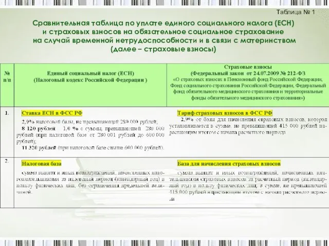 Сравнительная таблица по уплате единого социального налога (ЕСН) и страховых взносов на обязательное социальное страхование на с