- 1 Descriptive geometry Introduction

Содержание
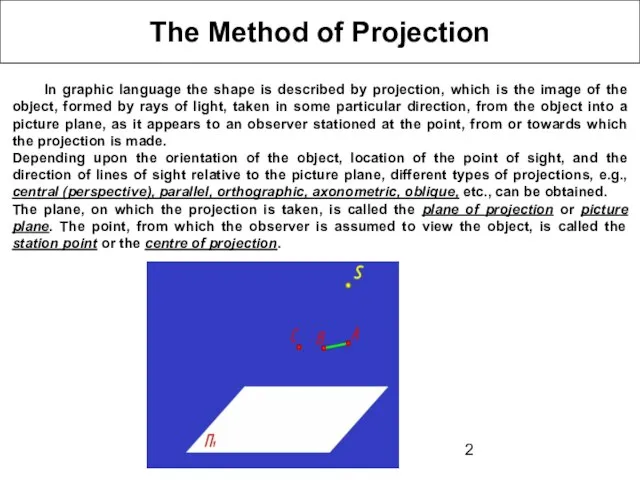
- 2. The Method of Projection In graphic language the shape is described by projection, which is the
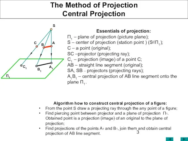
- 3. The Method of Projection Central Projection Essentials of projection: П1 – plane of projection (picture plane);
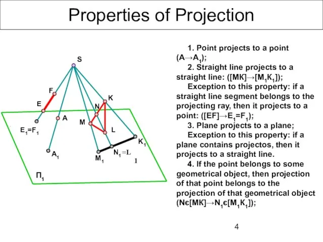
- 4. Properties of Projection 1. Point projects to a point (А→А1); 2. Straight line projects to a
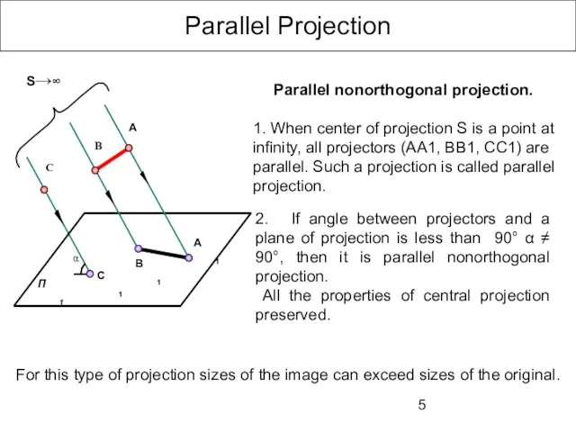
- 5. Parallel Projection 2. If angle between projectors and a plane of projection is less than 90°
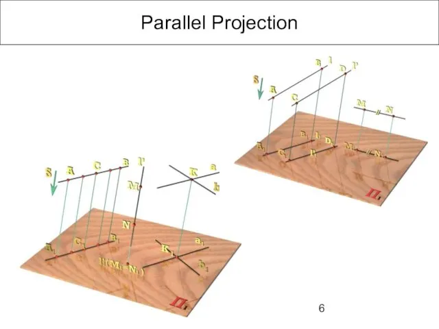
- 6. Parallel Projection
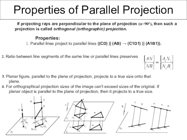
- 7. 2. Ratio between line segments of the same line or parallel lines preserves 3. Planar figure,
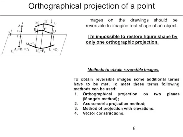
- 8. Orthographical projection of a point Images on the drawings should be reversible to imagine real shape
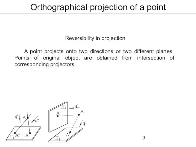
- 9. Orthographical projection of a point Reversibility in projection A point projects onto two directions or two
- 10. Monge’s method A point projects onto two mutually perpendicular principal planes (planes of projection). After that
- 11. Monge’s method Designations П1 – horizontal principal plane (plane of projection) - H; П2 – frontal
- 12. Concurrent points А and В — horizontally concurrent points C and D — frontally concurrent points
- 13. Orthographical projection of a point Some problem can be solved easier, if two principle planes of
- 14. Principal planes of projection
- 15. Orthographical projection of a point А (ХА , YA , ZA) x y z y П1
- 16. Straight Lines. Classification.
- 17. Orthographic projection of a Straight Line. Horizontal line Horizontal (horizontally parallel) – straight line, parallel to
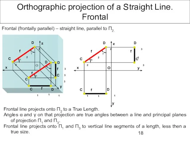
- 18. Orthographic projection of a Straight Line. Frontal Frontal line projects onto П2 to a True Length.
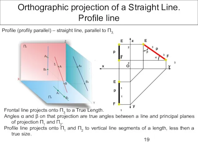
- 19. Orthographic projection of a Straight Line. Profile line Profile (profily parallel) – straight line, parallel to
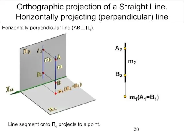
- 20. Orthographic projection of a Straight Line. Horizontally projecting (perpendicular) line Line segment onto П1 projects to
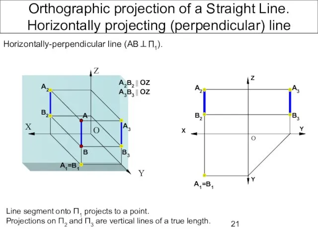
- 21. Orthographic projection of a Straight Line. Horizontally projecting (perpendicular) line Line segment onto П1 projects to
- 22. Orthographic projection of a Straight Line. Frontally projecting (perpendicular) line Frontally-perpendicular line (CD⊥П2). Line segment onto
- 23. Orthographic projection of a Straight Line. Frontally projecting (perpendicular) line Frontally-perpendicular line (CD⊥П2). Line segment onto
- 24. Orthographic projection of a Straight Line. Profily projecting (perpendicular) line Profily-perpendicular line (MN⊥П3). Line segment onto
- 25. Orthographic projection of a Straight Line. Profily projecting (perpendicular) line Profily-perpendicular line (MN⊥П3). Line segment onto
- 26. Oblique Line
- 27. Oblique Line neither parallel nor perpendicular to any principal plane of projection. Oblique line projects onto
- 28. Relative Position of a Line and a Plane Relative position of a Line and a Plane
- 29. Relative Position of Lines K and L, M and N – concurrent points Proper projections are
- 30. Intersecting с∩d=K
- 31. Parallel a║b
- 32. Skew (Crossing) ―
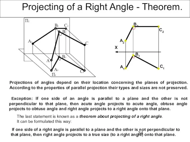
- 33. Projecting of a Right Angle - Theorem.
- 34. Projecting of a Right Angle - Theorem. Exception: If one side of an angle is parallel
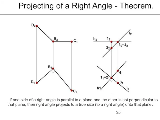
- 35. Projecting of a Right Angle - Theorem. If one side of a right angle is parallel
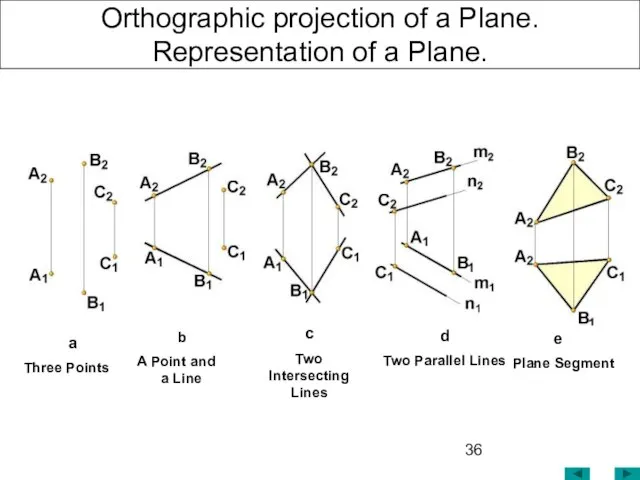
- 36. Orthographic projection of a Plane. Representation of a Plane. b A Point and a Line a
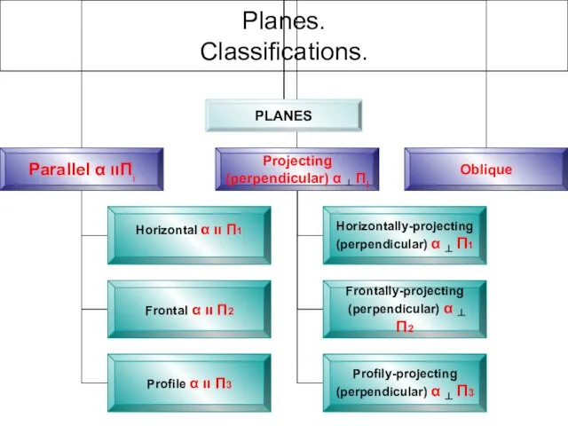
- 37. Planes. Classifications.
- 38. Oblique Plane Z Y' Y X Oblique plane neither parallel nor perpendicular to any principal plane
- 39. Principal Planes. Horizontal (principal) plane ((ABC) || ∏1) is a plane, parallel to horizontal principal plane
- 40. Principal Planes. Frontal (principal) plane ((ABC) || ∏2) is a plane, parallel to the frontal principal
- 41. Principal Planes. Profile (principal) plane ((ABC) || ∏3) is a plane, parallel to the profile principal
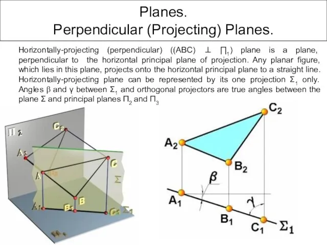
- 42. Planes. Perpendicular (Projecting) Planes. Horizontally-projecting (perpendicular) ((ABC) ⊥ ∏1) plane is a plane, perpendicular to the
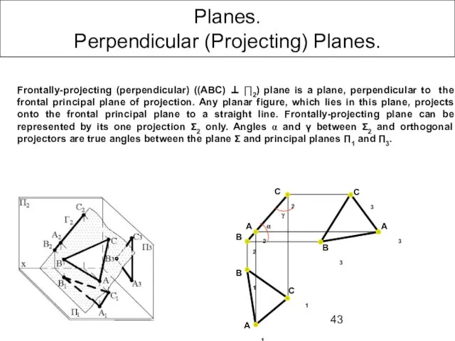
- 43. Planes. Perpendicular (Projecting) Planes. Frontally-projecting (perpendicular) ((ABC) ⊥ ∏2) plane is a plane, perpendicular to the
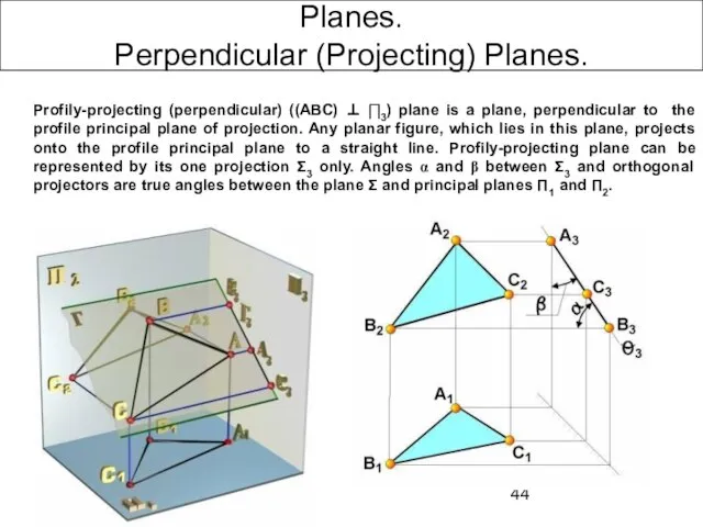
- 44. Planes. Perpendicular (Projecting) Planes. Profily-projecting (perpendicular) ((ABC) ⊥ ∏3) plane is a plane, perpendicular to the
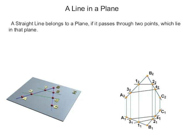
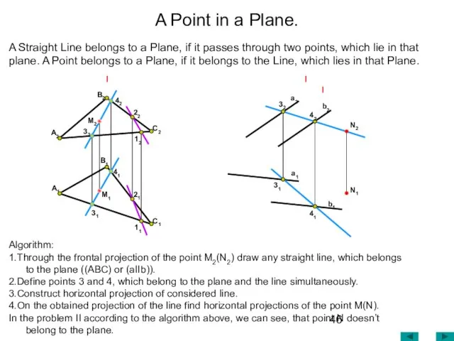
- 45. A Line in a Plane A Straight Line belongs to a Plane, if it passes through
- 46. A Point in a Plane. Algorithm: 1.Through the frontal projection of the point М2(N2) draw any
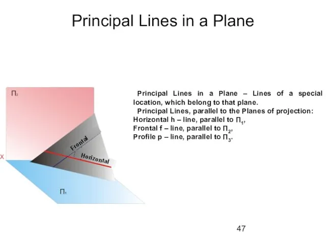
- 47. Principal Lines in a Plane Principal Lines in a Plane – Lines of a special location,
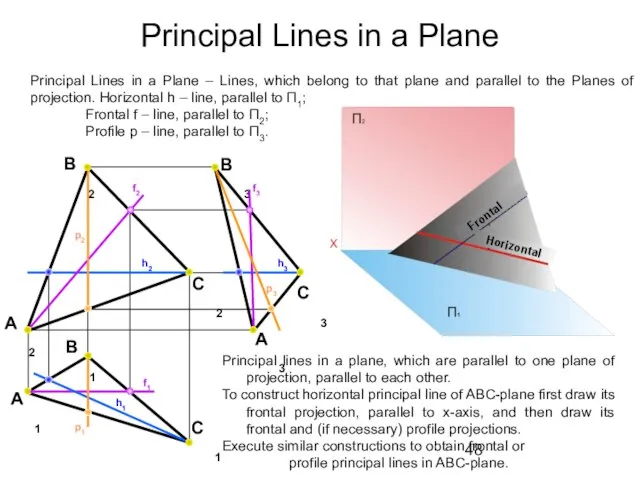
- 48. Principal Lines in a Plane B2 A2 C2 B3 A3 C1 B1 A1 Principal lines in
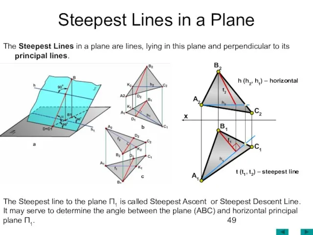
- 49. Steepest Lines in a Plane The Steepest Lines in a plane are lines, lying in this
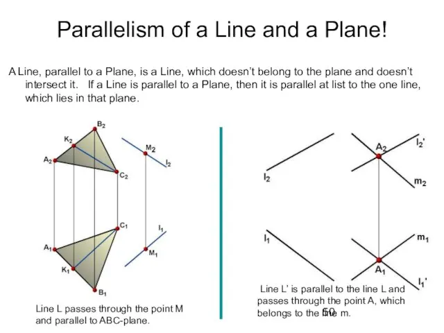
- 50. Parallelism of a Line and a Plane! A Line, parallel to a Plane, is a Line,
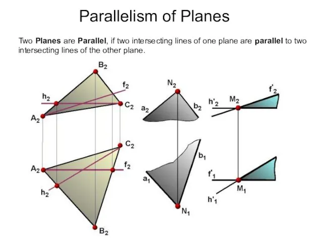
- 51. Two Planes are Parallel, if two intersecting lines of one plane are parallel to two intersecting
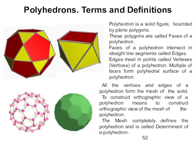
- 52. Polyhedrons. Terms and Definitions Polyhedron is a solid figure, bounded by plane polygons. These polygons are
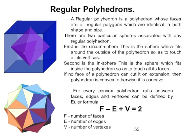
- 53. Regular Polyhedrons. A Regular polyhedron is a polyhedron whose faces are all regular polygons which are
- 54. Regular Polyhedrons. tetrahedron 4 triangles cube 6squares octahedron 8 triangles dodecahedron 12 pentagons icosahedron 20 triangles
- 55. Prism and Pyramid
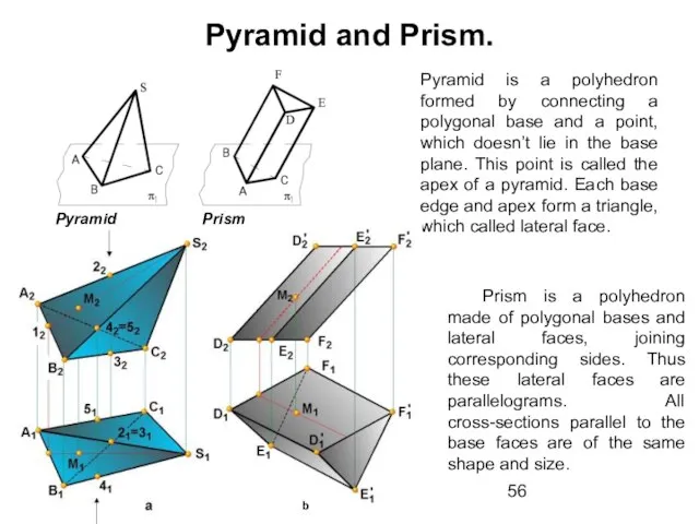
- 56. Pyramid and Prism. Pyramid is a polyhedron formed by connecting a polygonal base and a point,
- 57. Polyhedrons. Visibility definition Prism (Lateral edges intersect in ∞). A1 D1 C2 C1 y y z
- 58. Polyhedrons. Pyramid Pyramid - Lateral edges meet in one common point (Apex). B1 y A2 A1
- 59. B1 y A2 A1 x B2 C1 C2 y z S2 S1 Pyramid - Lateral edges
- 61. Скачать презентацию
Слайд 3The Method of Projection
Central Projection
Essentials of projection:
П1 – plane of projection (picture
The Method of Projection
Central Projection
Essentials of projection:
П1 – plane of projection (picture
Слайд 4Properties of Projection
1. Point projects to a point (А→А1);
2. Straight line projects
Properties of Projection
1. Point projects to a point (А→А1);
2. Straight line projects
Слайд 5Parallel Projection
2. If angle between projectors and a plane of projection is less
Parallel Projection
2. If angle between projectors and a plane of projection is less
Слайд 6Parallel Projection
Parallel Projection
Слайд 72. Ratio between line segments of the same line or parallel lines
2. Ratio between line segments of the same line or parallel lines
Слайд 8Orthographical projection of a point
Images on the drawings should be reversible to
Orthographical projection of a point
Images on the drawings should be reversible to
Слайд 9Orthographical projection of a point
Reversibility in projection
A point projects onto two
Orthographical projection of a point
Reversibility in projection
A point projects onto two
Слайд 10Monge’s method
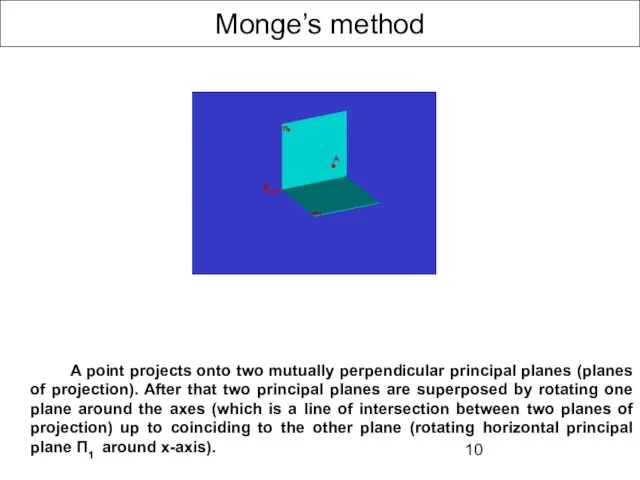
A point projects onto two mutually perpendicular principal planes (planes of
Monge’s method
A point projects onto two mutually perpendicular principal planes (planes of
Слайд 11Monge’s method
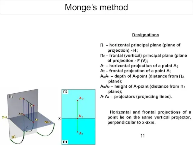
Designations
П1 – horizontal principal plane (plane of projection) - H;
П2 –
Monge’s method
Designations
П1 – horizontal principal plane (plane of projection) - H;
П2 –
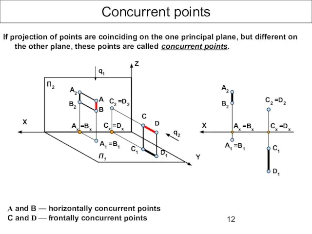
Слайд 12Concurrent points
А and В — horizontally concurrent points
C and D —
Concurrent points
А and В — horizontally concurrent points
C and D —
Слайд 13Orthographical projection of a point
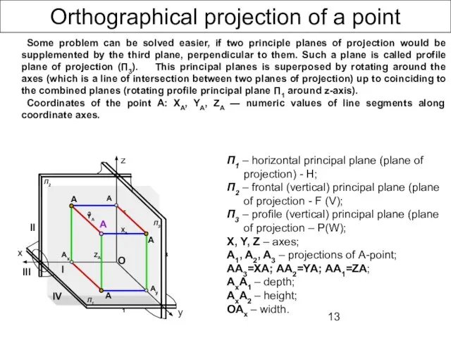
Some problem can be solved easier, if two
Orthographical projection of a point
Some problem can be solved easier, if two
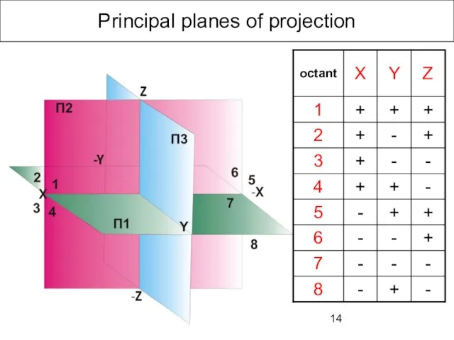
Слайд 14Principal planes of projection
Principal planes of projection
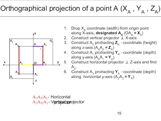
Слайд 15Orthographical projection of a point А (ХА , YA , ZA)
x
y
z
y
П1
П2
П3
Drop ХА
Orthographical projection of a point А (ХА , YA , ZA)
x
y
z
y
П1
П2
П3
Drop ХА
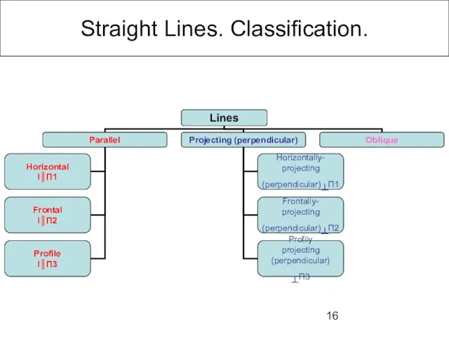
Слайд 16Straight Lines. Classification.
Straight Lines. Classification.
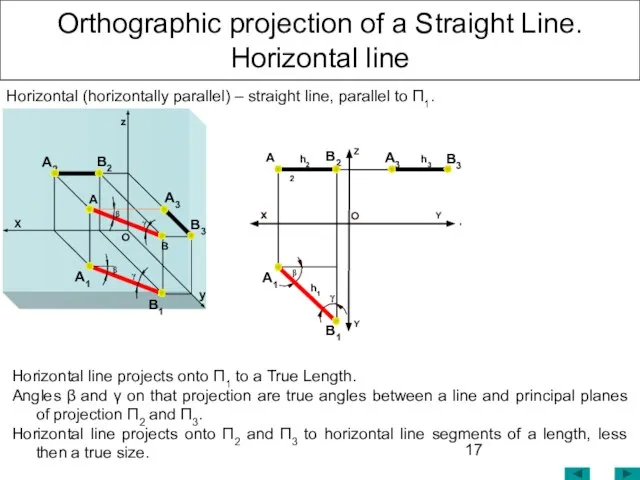
Слайд 17Orthographic projection of a Straight Line.
Horizontal line
Horizontal (horizontally parallel) – straight line,
Orthographic projection of a Straight Line.
Horizontal line
Horizontal (horizontally parallel) – straight line,
Слайд 18Orthographic projection of a Straight Line.
Frontal
Frontal line projects onto П2 to
Orthographic projection of a Straight Line.
Frontal
Frontal line projects onto П2 to
Слайд 19Orthographic projection of a Straight Line.
Profile line
Profile (profily parallel) – straight
Orthographic projection of a Straight Line.
Profile line
Profile (profily parallel) – straight
Слайд 20Orthographic projection of a Straight Line. Horizontally projecting (perpendicular) line
Line segment onto
Orthographic projection of a Straight Line. Horizontally projecting (perpendicular) line
Line segment onto
Слайд 21Orthographic projection of a Straight Line. Horizontally projecting (perpendicular) line
Line segment onto
Orthographic projection of a Straight Line. Horizontally projecting (perpendicular) line
Line segment onto
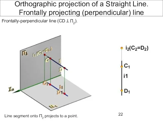
Слайд 22Orthographic projection of a Straight Line. Frontally projecting (perpendicular) line
Frontally-perpendicular line (CD⊥П2).
Line
Orthographic projection of a Straight Line. Frontally projecting (perpendicular) line
Frontally-perpendicular line (CD⊥П2).
Line
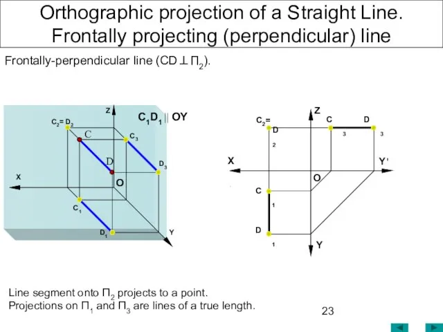
Слайд 23Orthographic projection of a Straight Line. Frontally projecting (perpendicular) line
Frontally-perpendicular line (CD⊥П2).
Line
Orthographic projection of a Straight Line. Frontally projecting (perpendicular) line
Frontally-perpendicular line (CD⊥П2).
Line
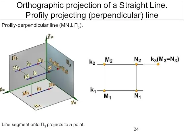
Слайд 24Orthographic projection of a Straight Line.
Profily projecting (perpendicular) line
Profily-perpendicular line (MN⊥П3).
Line
Orthographic projection of a Straight Line.
Profily projecting (perpendicular) line
Profily-perpendicular line (MN⊥П3).
Line
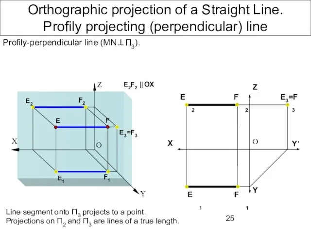
Слайд 25Orthographic projection of a Straight Line.
Profily projecting (perpendicular) line
Profily-perpendicular line (MN⊥П3).
Line
Orthographic projection of a Straight Line.
Profily projecting (perpendicular) line
Profily-perpendicular line (MN⊥П3).
Line
Слайд 26Oblique Line
Oblique Line
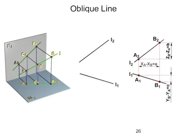
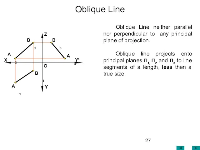
Слайд 27 Oblique Line neither parallel nor perpendicular to any principal plane of projection.
Oblique Line neither parallel nor perpendicular to any principal plane of projection.
Слайд 28Relative Position of a Line and a Plane
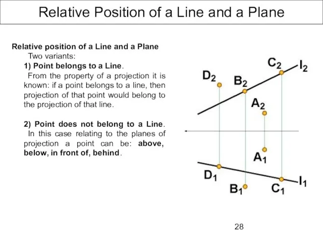
Relative position of a Line
Relative Position of a Line and a Plane
Relative position of a Line
Слайд 29Relative Position of Lines
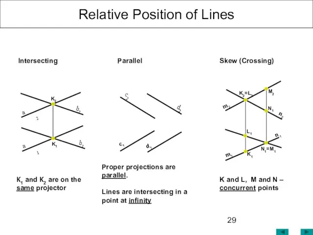
K and L, M and N – concurrent points
Relative Position of Lines
K and L, M and N – concurrent points
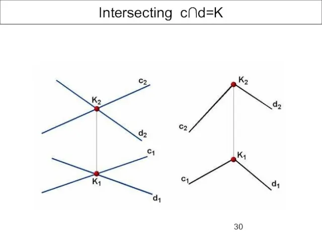
Слайд 30Intersecting с∩d=K
Intersecting с∩d=K
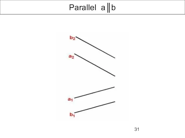
Слайд 31Parallel a║b
Parallel a║b
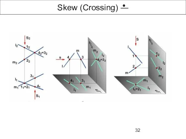
Слайд 32Skew (Crossing) ―
Skew (Crossing) ―
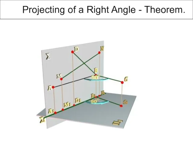
Слайд 33 Projecting of a Right Angle - Theorem.
Projecting of a Right Angle - Theorem.
Слайд 34 Projecting of a Right Angle - Theorem.
Exception: If one side of
Projecting of a Right Angle - Theorem.
Exception: If one side of
Слайд 35 Projecting of a Right Angle - Theorem.
If one side of a
Projecting of a Right Angle - Theorem.
If one side of a
Слайд 36Orthographic projection of a Plane.
Representation of a Plane.
b
A Point and
Orthographic projection of a Plane.
Representation of a Plane.
b
A Point and
Слайд 37Planes.
Classifications.
Planes.
Classifications.
Слайд 38Oblique Plane
Z
Y'
Y
X
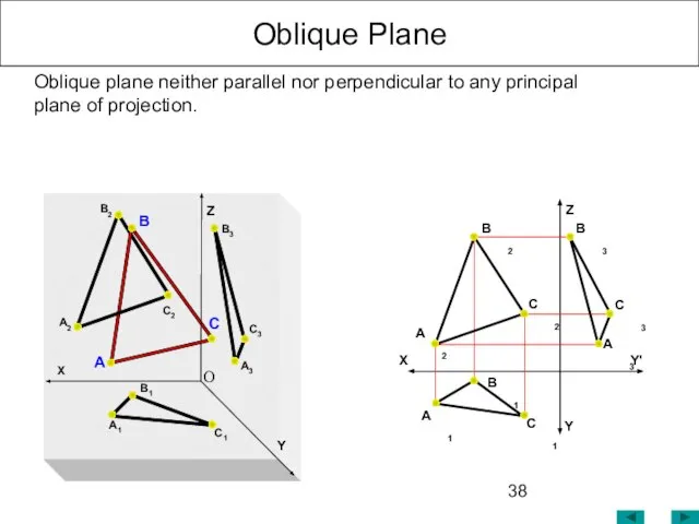
Oblique plane neither parallel nor perpendicular to any principal plane of
Oblique Plane
Z
Y'
Y
X
Oblique plane neither parallel nor perpendicular to any principal plane of
Слайд 39Principal Planes.
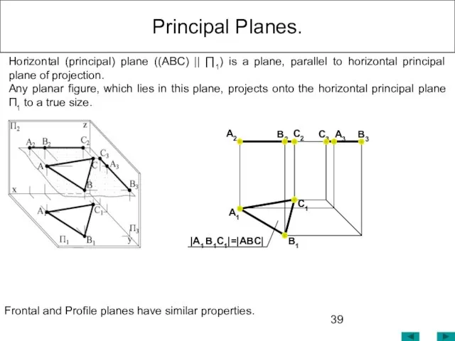
Horizontal (principal) plane ((ABC) || ∏1) is a plane, parallel
Principal Planes.
Horizontal (principal) plane ((ABC) || ∏1) is a plane, parallel
Слайд 40Principal Planes.
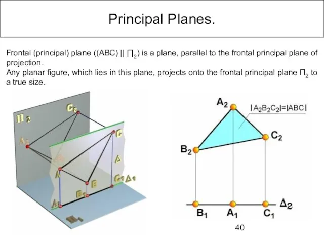
Frontal (principal) plane ((ABC) || ∏2) is a plane, parallel to
Principal Planes.
Frontal (principal) plane ((ABC) || ∏2) is a plane, parallel to
Слайд 41Principal Planes.
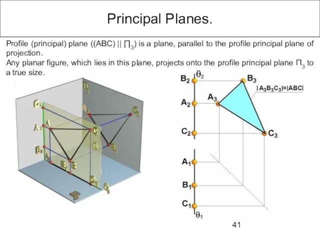
Profile (principal) plane ((ABC) || ∏3) is a plane, parallel to
Principal Planes.
Profile (principal) plane ((ABC) || ∏3) is a plane, parallel to
Слайд 42Planes.
Perpendicular (Projecting) Planes.
Horizontally-projecting (perpendicular) ((ABC) ⊥ ∏1) plane is a plane,
Planes.
Perpendicular (Projecting) Planes.
Horizontally-projecting (perpendicular) ((ABC) ⊥ ∏1) plane is a plane,
Слайд 43Planes.
Perpendicular (Projecting) Planes.
Frontally-projecting (perpendicular) ((ABC) ⊥ ∏2) plane is a plane, perpendicular
Planes.
Perpendicular (Projecting) Planes.
Frontally-projecting (perpendicular) ((ABC) ⊥ ∏2) plane is a plane, perpendicular
Слайд 44Planes.
Perpendicular (Projecting) Planes.
Profily-projecting (perpendicular) ((ABC) ⊥ ∏3) plane is a plane, perpendicular
Planes.
Perpendicular (Projecting) Planes.
Profily-projecting (perpendicular) ((ABC) ⊥ ∏3) plane is a plane, perpendicular
Слайд 45A Line in a Plane
A Straight Line belongs to a Plane, if
A Line in a Plane
A Straight Line belongs to a Plane, if
Слайд 46A Point in a Plane.
Algorithm:
1.Through the frontal projection of the point
A Point in a Plane.
Algorithm:
1.Through the frontal projection of the point
Слайд 47Principal Lines in a Plane
Principal Lines in a Plane – Lines of
Principal Lines in a Plane
Principal Lines in a Plane – Lines of
Слайд 48Principal Lines in a Plane
B2
A2
C2
B3
A3
C1
B1
A1
Principal lines in a plane, which are parallel
Principal Lines in a Plane
B2
A2
C2
B3
A3
C1
B1
A1
Principal lines in a plane, which are parallel
Слайд 49Steepest Lines in a Plane
The Steepest Lines in a plane are lines,
Steepest Lines in a Plane
The Steepest Lines in a plane are lines,
Слайд 50Parallelism of a Line and a Plane!
A Line, parallel to a
Parallelism of a Line and a Plane!
A Line, parallel to a
Слайд 51 Two Planes are Parallel, if two intersecting lines of one plane are
Two Planes are Parallel, if two intersecting lines of one plane are
Слайд 52Polyhedrons. Terms and Definitions
Polyhedron is a solid figure, bounded by plane polygons.
Polyhedrons. Terms and Definitions
Polyhedron is a solid figure, bounded by plane polygons.
Слайд 53Regular Polyhedrons.
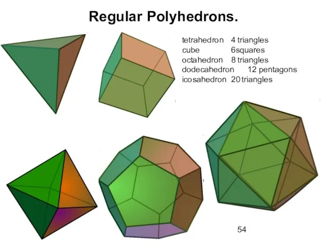
A Regular polyhedron is a polyhedron whose faces are all
Regular Polyhedrons.
A Regular polyhedron is a polyhedron whose faces are all
Слайд 54Regular Polyhedrons.
tetrahedron 4 triangles
cube 6squares
octahedron 8 triangles
dodecahedron 12 pentagons
icosahedron 20 triangles
Regular Polyhedrons.
tetrahedron 4 triangles
cube 6squares
octahedron 8 triangles
dodecahedron 12 pentagons
icosahedron 20 triangles
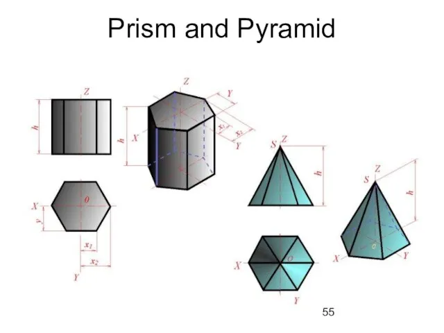
Слайд 55Prism and Pyramid
Prism and Pyramid
Слайд 56Pyramid and Prism.
Pyramid is a polyhedron formed by connecting a polygonal base
Pyramid and Prism.
Pyramid is a polyhedron formed by connecting a polygonal base
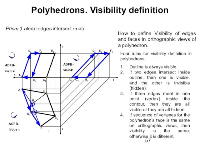
Слайд 57Polyhedrons. Visibility definition
Prism (Lateral edges intersect in ∞).
A1
D1
C2
C1
y
y
z
F1
Е1
Е2
F2
D2
x
A2
B2
B1
Outline is always
Polyhedrons. Visibility definition
Prism (Lateral edges intersect in ∞).
A1
D1
C2
C1
y
y
z
F1
Е1
Е2
F2
D2
x
A2
B2
B1
Outline is always
Слайд 58Polyhedrons. Pyramid
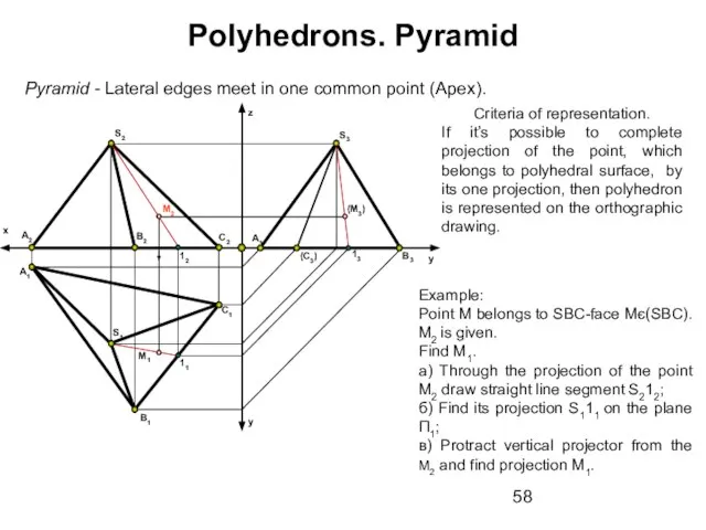
Pyramid - Lateral edges meet in one common point (Apex).
B1
y
A2
A1
x
B2
C1
C2
y
z
S2
S1
Example:
Point
Polyhedrons. Pyramid
Pyramid - Lateral edges meet in one common point (Apex).
B1
y
A2
A1
x
B2
C1
C2
y
z
S2
S1
Example:
Point
Слайд 59B1
y
A2
A1
x
B2
C1
C2
y
z
S2
S1
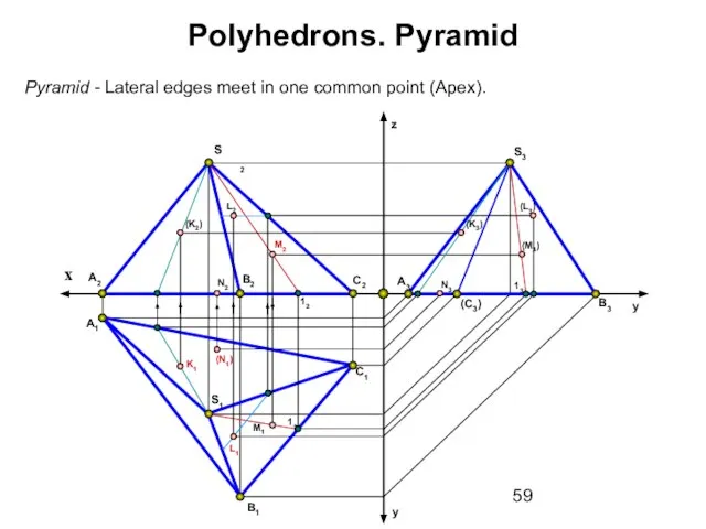
Pyramid - Lateral edges meet in one common point (Apex).
Polyhedrons. Pyramid
B1
y
A2
A1
x
B2
C1
C2
y
z
S2
S1
Pyramid - Lateral edges meet in one common point (Apex).
Polyhedrons. Pyramid
 Реклама во Франции. Глазкова 22.04.2019
 ПРЕЗЕНТАЦИЯ КУРСОВОЙ
 Как я провела этот год
 Препараты гормонов, их синтетических заменителей
  Ценим Ваше время!
 Балльно-рейтинговая система на Образовательном портале ОмГПУ
 Описание системы
 ИЗМЕНЕНИЯ В ПЛАНЕ РАЗВИТИЯ 2011 Для Агентов Казахстана.
 Преобразование вида и состава изображений. Графическая работа
 Создание презентаций
 Школа родительского мастерства. Решение конфликтов
 БАНКОВСКИЙ СЕКТОР НА ФОНДОВОМ РЫНКЕ РФ
 Схема микроразмножения
 Трансакционные издержки
 Строительная геотехнология
 ОПЫТ ВНЕДРЕНИЯ ИНДУСТРИАЛЬНОЙ МОДЕЛИ УПРАВЛЕНИЯ КАЧЕСТВОМ МЕДИЦИНСКОЙ ПОМОЩИВ МНОГОПРОФИЛЬНОЙ БОЛЬНИЦЕ (антикризисное управле
 Первые русские князья
 Лекция на тему: Физиологические основы применения азотных удобрений
 Корпоративная социальная ответственность как основа надежного бренда на примере компании «Балтика»
 Пасха Красная
 Астафьев «Капалуха»
 Развитие коммуникативной культуры учащихся на уроках немецкого языка и во внеклассной работе.
 Рождение феодального общества у древних славян.
 Ержан ағай слайд дайын
 Имя освещает жизненный путь человека
 Общественное здоровье и организация здравоохранения
  Породы Собак
 209n-изменение косгу