- Transformation of a Drawing

Содержание
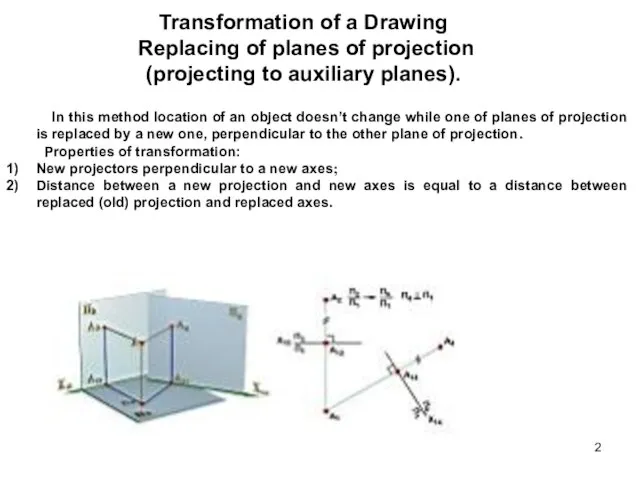
- 2. Transformation of a Drawing Replacing of planes of projection (projecting to auxiliary planes). In this method
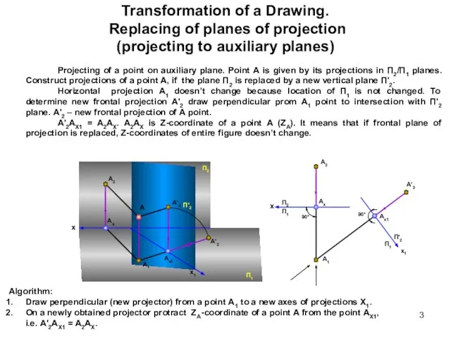
- 3. Transformation of a Drawing. Replacing of planes of projection (projecting to auxiliary planes) Projecting of a
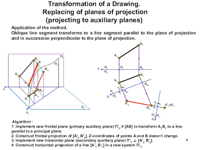
- 4. Transformation of a Drawing. Replacing of planes of projection (projecting to auxiliary planes) Application of the
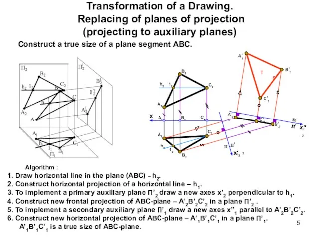
- 5. Transformation of a Drawing. Replacing of planes of projection (projecting to auxiliary planes) Construct a true
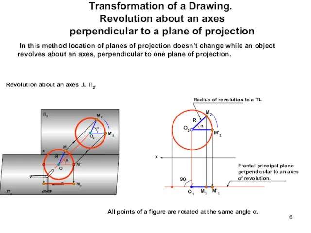
- 6. Transformation of a Drawing. Revolution about an axes perpendicular to a plane of projection In this
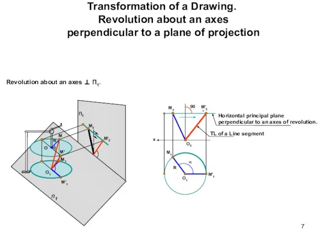
- 7. Transformation of a Drawing. Revolution about an axes perpendicular to a plane of projection Revolution about
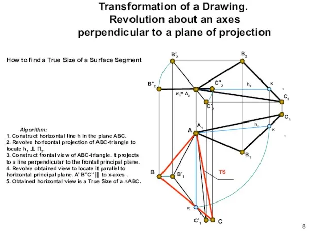
- 8. Transformation of a Drawing. Revolution about an axes perpendicular to a plane of projection B2 A2
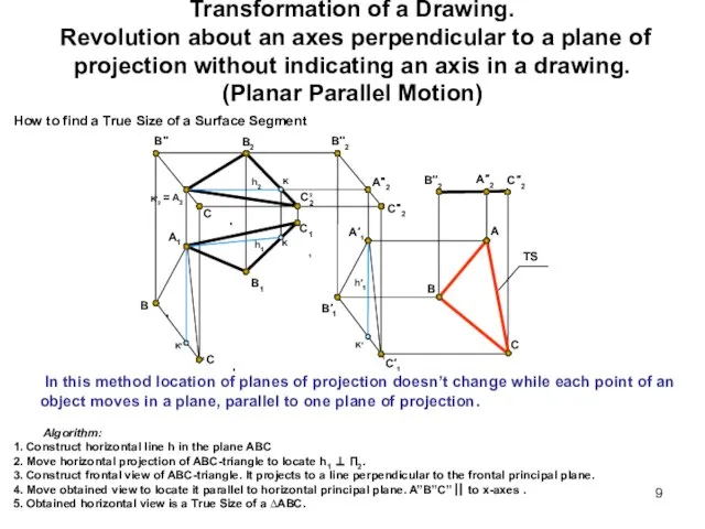
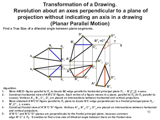
- 9. Transformation of a Drawing. Revolution about an axes perpendicular to a plane of projection without indicating
- 10. Transformation of a Drawing. Revolution about an axes perpendicular to a plane of projection without indicating
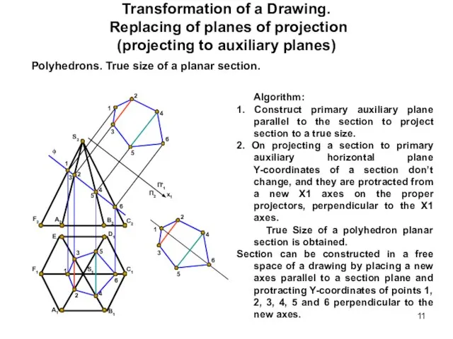
- 11. Transformation of a Drawing. Replacing of planes of projection (projecting to auxiliary planes) Polyhedrons. True size
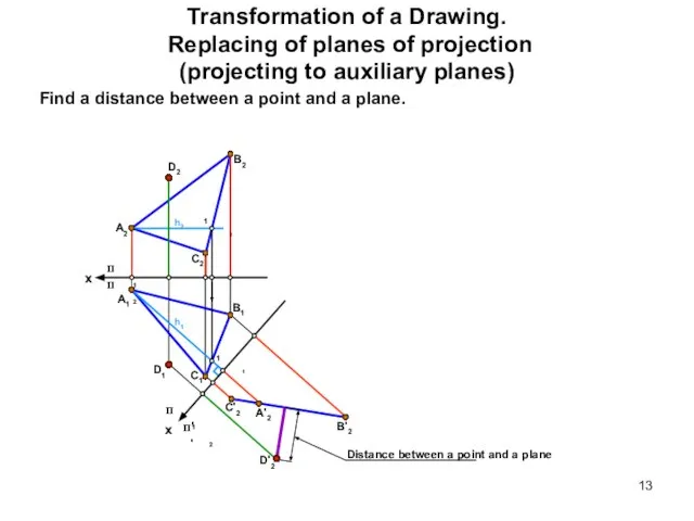
- 12. Transformation of a Drawing. Replacing of planes of projection (projecting to auxiliary planes) Find a distance
- 13. Transformation of a Drawing. Replacing of planes of projection (projecting to auxiliary planes) Find a distance
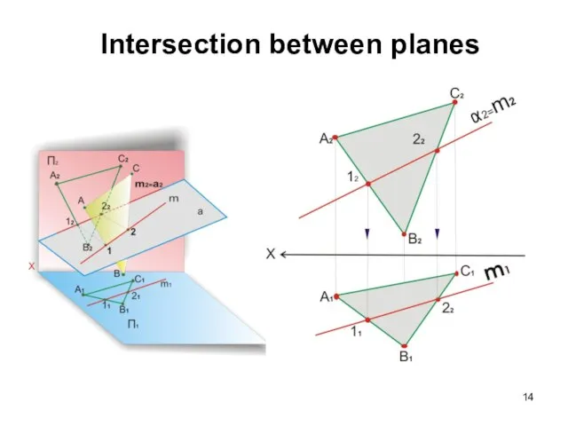
- 14. Intersection between planes
- 15. Intersection between a Line and a Plane A Line and a Plane have one common Point
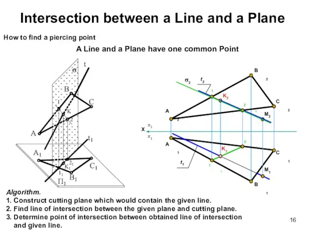
- 16. Intersection between a Line and a Plane A Line and a Plane have one common Point
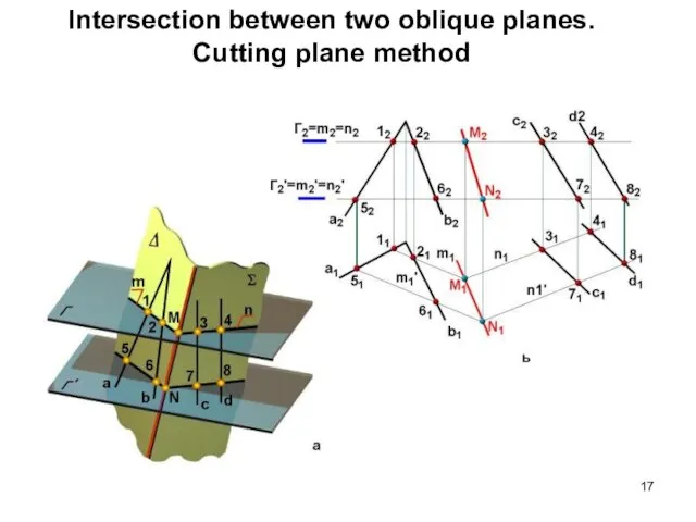
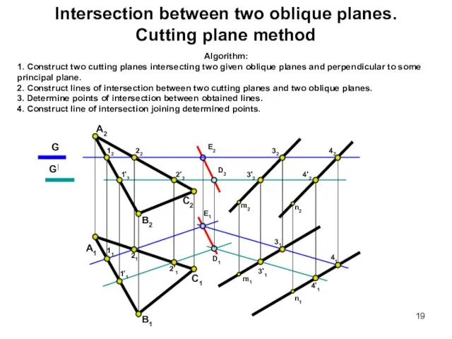
- 17. Intersection between two oblique planes. Cutting plane method
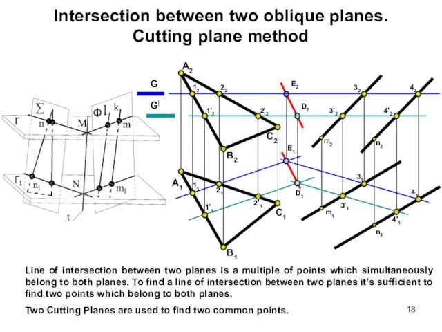
- 18. Intersection between two oblique planes. Cutting plane method Line of intersection between two planes is a
- 19. Intersection between two oblique planes. Cutting plane method Algorithm: 1. Construct two cutting planes intersecting two
- 20. Axonometric projection The word 'axonometry' (Greek) consists of two words: 'axon'—axis and 'metreo'—I measure, and means
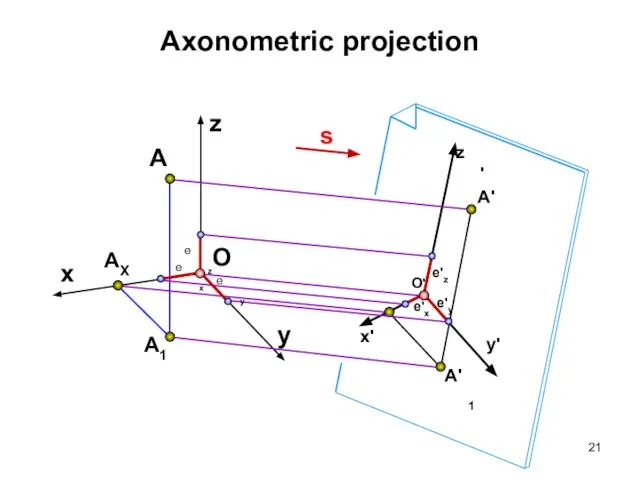
- 21. Axonometric projection A1 x AX A O z y
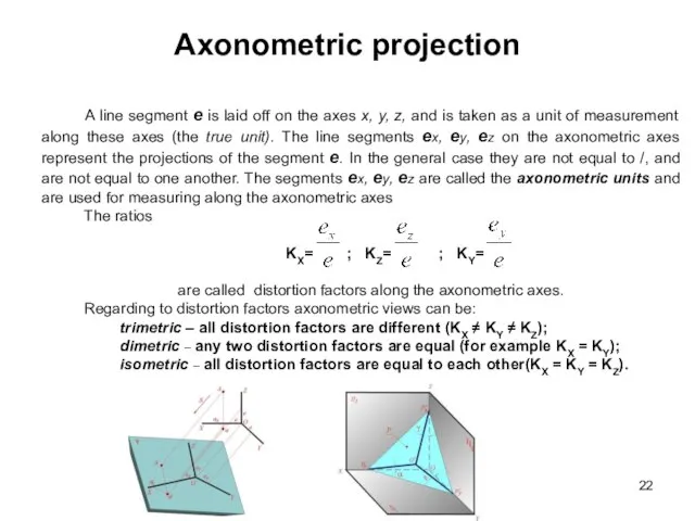
- 22. Axonometric projection A line segment e is laid off on the axes x, y, z, and
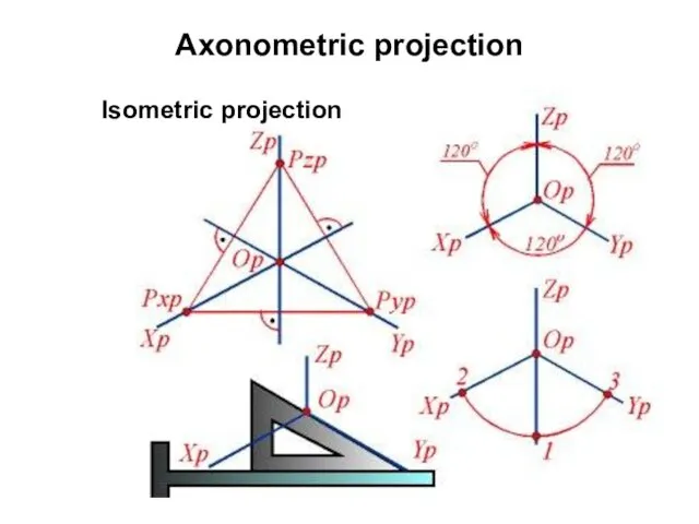
- 23. Axonometric projection Isometric projection
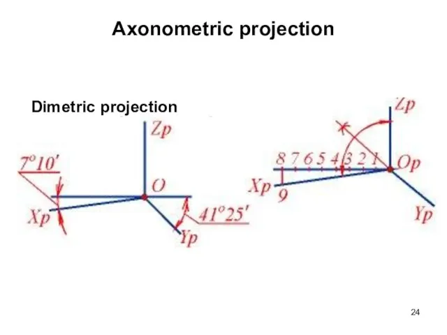
- 24. Axonometric projection Dimetric projection
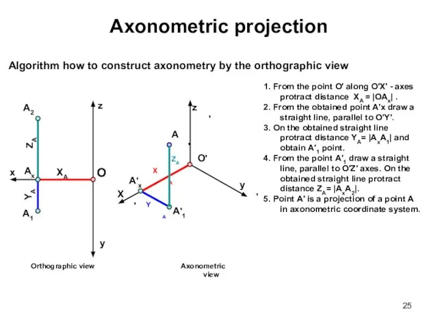
- 25. 1. From the point О′ along О′Х′ - axes protract distance XA = |ОAx| . 2.
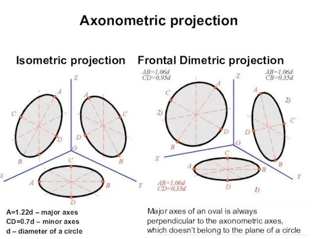
- 26. Axonometric projection Isometric projection Frontal Dimetric projection A=1.22d – major axes CD=0.7d – minor axes d
- 28. Axonometric projection Algorithm: 1. In axonometric coordinate system X’, Y’, Z’ protract points 1, 8, 2,
- 29. Axonometric projection Algorithm how to construct orthographic view by the axonometry Given data: cone of revolution
- 30. Orthogonal frontal isometric projection
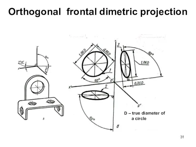
- 31. Orthogonal frontal dimetric projection D – true diameter of a circle
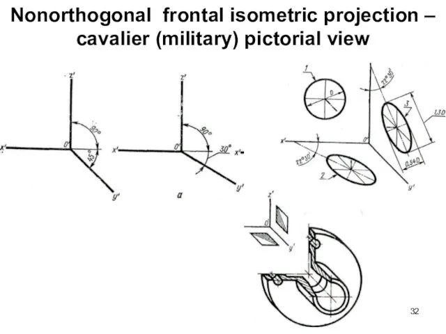
- 32. Nonorthogonal frontal isometric projection – cavalier (military) pictorial view
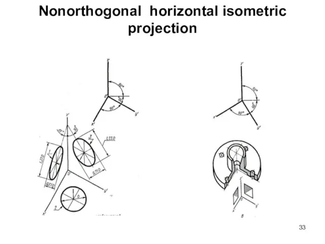
- 33. Nonorthogonal horizontal isometric projection
- 35. Скачать презентацию
Слайд 3Transformation of a Drawing. Replacing of planes of projection
(projecting to auxiliary
Transformation of a Drawing. Replacing of planes of projection (projecting to auxiliary
Слайд 4Transformation of a Drawing. Replacing of planes of projection
(projecting to auxiliary
Transformation of a Drawing. Replacing of planes of projection (projecting to auxiliary
Слайд 5Transformation of a Drawing. Replacing of planes of projection
(projecting to auxiliary
Transformation of a Drawing. Replacing of planes of projection (projecting to auxiliary
Слайд 6Transformation of a Drawing. Revolution about an axes
perpendicular to a plane
Transformation of a Drawing. Revolution about an axes perpendicular to a plane
Слайд 7Transformation of a Drawing. Revolution about an axes
perpendicular to a plane
Transformation of a Drawing. Revolution about an axes perpendicular to a plane
Слайд 8Transformation of a Drawing. Revolution about an axes
perpendicular to a plane
Transformation of a Drawing. Revolution about an axes perpendicular to a plane
Слайд 9Transformation of a Drawing. Revolution about an axes perpendicular to a plane
Transformation of a Drawing. Revolution about an axes perpendicular to a plane
Слайд 10Transformation of a Drawing. Revolution about an axes perpendicular to a plane
Transformation of a Drawing. Revolution about an axes perpendicular to a plane
Слайд 11Transformation of a Drawing. Replacing of planes of projection
(projecting to auxiliary
Transformation of a Drawing. Replacing of planes of projection (projecting to auxiliary
Слайд 12Transformation of a Drawing. Replacing of planes of projection
(projecting to auxiliary
Transformation of a Drawing. Replacing of planes of projection (projecting to auxiliary

Слайд 13Transformation of a Drawing. Replacing of planes of projection
(projecting to auxiliary
Transformation of a Drawing. Replacing of planes of projection (projecting to auxiliary
Слайд 14Intersection between planes
Intersection between planes
Слайд 15Intersection between a Line and a Plane
A Line and a Plane have
Intersection between a Line and a Plane
A Line and a Plane have
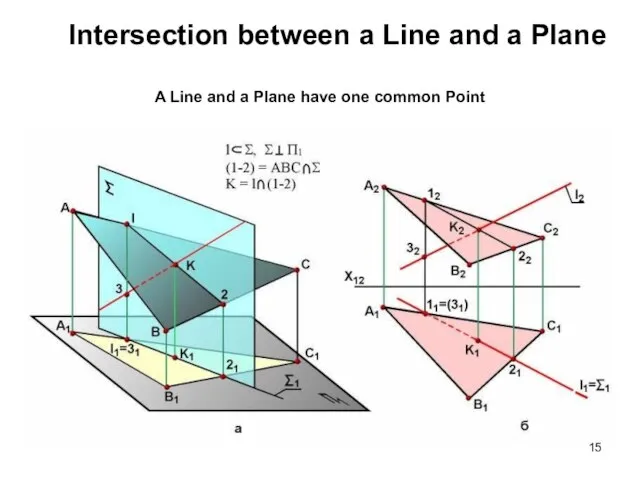
Слайд 16Intersection between a Line and a Plane
A Line and a Plane have
Intersection between a Line and a Plane
A Line and a Plane have
Слайд 17Intersection between two oblique planes.
Cutting plane method
Intersection between two oblique planes.
Cutting plane method
Слайд 18Intersection between two oblique planes.
Cutting plane method
Line of intersection between two planes
Intersection between two oblique planes.
Cutting plane method
Line of intersection between two planes
Слайд 19Intersection between two oblique planes.
Cutting plane method
Algorithm:
1. Construct two cutting planes intersecting
Intersection between two oblique planes.
Cutting plane method
Algorithm:
1. Construct two cutting planes intersecting
Слайд 20Axonometric projection
The word 'axonometry' (Greek) consists of two words: 'axon'—axis and 'metreo'—I
Axonometric projection
The word 'axonometry' (Greek) consists of two words: 'axon'—axis and 'metreo'—I
Слайд 21Axonometric projection
A1
x
AX
A
O
z
y
Axonometric projection
A1
x
AX
A
O
z
y
Слайд 22Axonometric projection
A line segment e is laid off on the axes
Axonometric projection
A line segment e is laid off on the axes
Слайд 23Axonometric projection
Isometric projection
Axonometric projection
Isometric projection
Слайд 24Axonometric projection
Dimetric projection
Axonometric projection
Dimetric projection
Слайд 251. From the point О′ along О′Х′ - axes protract distance XA
1. From the point О′ along О′Х′ - axes protract distance XA
Слайд 26Axonometric projection
Isometric projection
Frontal Dimetric projection
A=1.22d – major axes
CD=0.7d – minor axes
d –
Axonometric projection
Isometric projection
Frontal Dimetric projection
A=1.22d – major axes
CD=0.7d – minor axes
d –
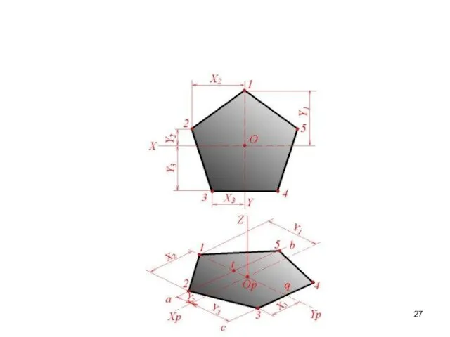
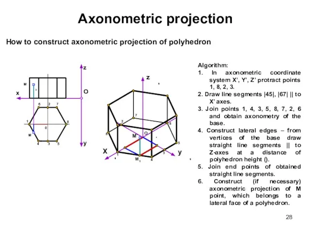
Слайд 28Axonometric projection
Algorithm:
1. In axonometric coordinate system X’, Y’, Z’ protract points 1,
Axonometric projection
Algorithm:
1. In axonometric coordinate system X’, Y’, Z’ protract points 1,
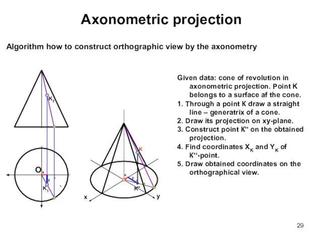
Слайд 29Axonometric projection
Algorithm how to construct orthographic view by the axonometry
Given data:
Axonometric projection
Algorithm how to construct orthographic view by the axonometry
Given data:
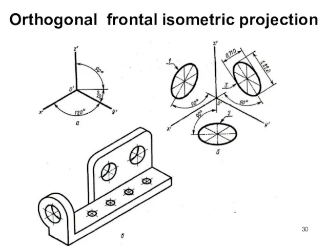
Слайд 30Orthogonal frontal isometric projection
Orthogonal frontal isometric projection
Слайд 31Orthogonal frontal dimetric projection
D – true diameter of a circle
Orthogonal frontal dimetric projection
D – true diameter of a circle
Слайд 32Nonorthogonal frontal isometric projection – cavalier (military) pictorial view
Nonorthogonal frontal isometric projection – cavalier (military) pictorial view
Слайд 33Nonorthogonal horizontal isometric projection
Nonorthogonal horizontal isometric projection
 УРОК 5 Понедельник 26 июля 2010 Начало в 15.55 по московском времени 1. - презентация
 Понедельник - встреча Масленницы
 Котлеты по-киевски
 КАЛЕНДАРЬЗНАМЕНАТЕЛЬНЫХ ДАТ (НА МАРТ 2012 ГОДА)
 Архитектура ИКТ – организационная, юридическая и технологическая модель взаимодействий
 ПРИЧИНЫ ДЛЯ ТОГО, ЧТОБЫ ИМЕТЬ НЕЗАВИСИМЫЙ РЕГУЛИРУЮЩИЙ ОРГАН: НЕБОЛЬШОЙ ОТДЫХ
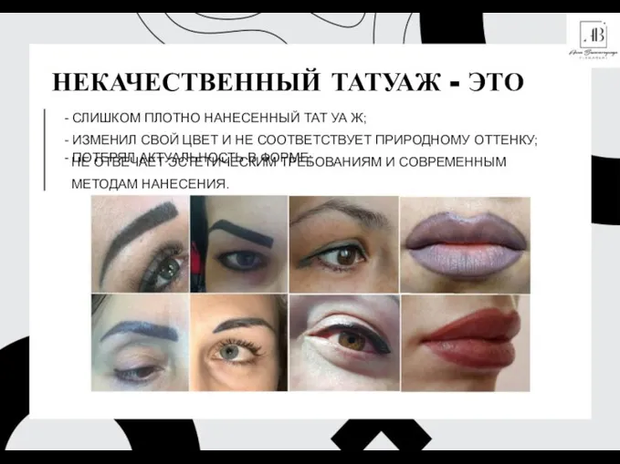 Некачественный татуаж. Способы исправления
 Русская лексика с точки зрения сферы ее употребления
 Выполнение домашнего задания
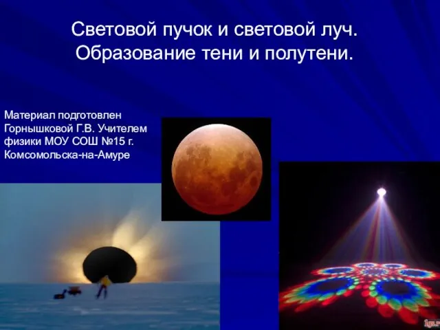 Световой пучок и световой луч.Образование тени и полутени.
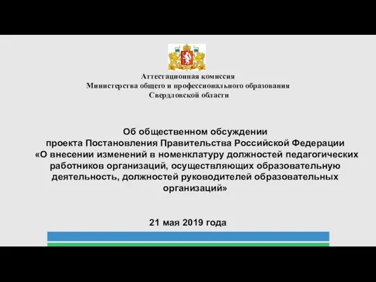 О внесении изменений в номенклатуру должностей педагогических работников организаций образовательной деятельности
 Презентация ДСТИ+ (3)
 MadameTussaud’s Музей Восковых фигур Мадам Тюссо
 Мы наследники барабинских татар
 Короленко "В дурном обществе"
 Межличностная коммуникация
 eBook Academic Collection
 Ознакомление с окружающим миром: зимующие птицы нашего края
 Выразительные словообразовательные средства Учитель Омельчук Е.И.
 Презентация на тему Загадки по ПДД
  Я – талант, мы все – таланты!. Проект о спортсменах. Выпуск 1
 Требования к оформлению мультимедийных презентаций
 Коммуникативные сервисы электронных библиотек ВУЗов
 Любовь Шамовна Вассерман
 Залилов (Джалиль) Муса Мустафович 1906 – 1944 г
 Школа России
 Привитие навыков здорового образа жизни у школьников
 Организация маркетинга в вузе