- 13 September Huawei Seminar (6) (1)

Содержание
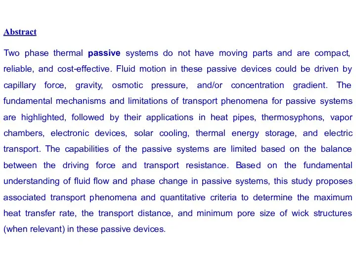
- 2. Abstract Two phase thermal passive systems do not have moving parts and are compact, reliable, and
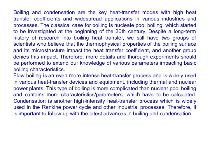
- 3. Boiling and condensation are the key heat-transfer modes with high heat transfer coefficients and widespread applications
- 4. Part 1 Contracts: Short Historical overeviews of the Porous media laboratory Luikov HMTI NAN, Belarus with
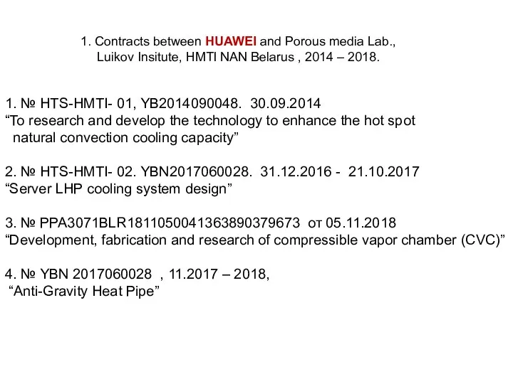
- 5. 1. № HTS-HMTI- 01, YB2014090048. 30.09.2014 “To research and develop the technology to enhance the hot
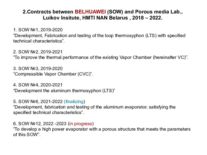
- 6. 2.Contracts between BELHUAWEI (SOW) and Porous media Lab., Luikov Insitute, HMTI NAN Belarus , 2018 –
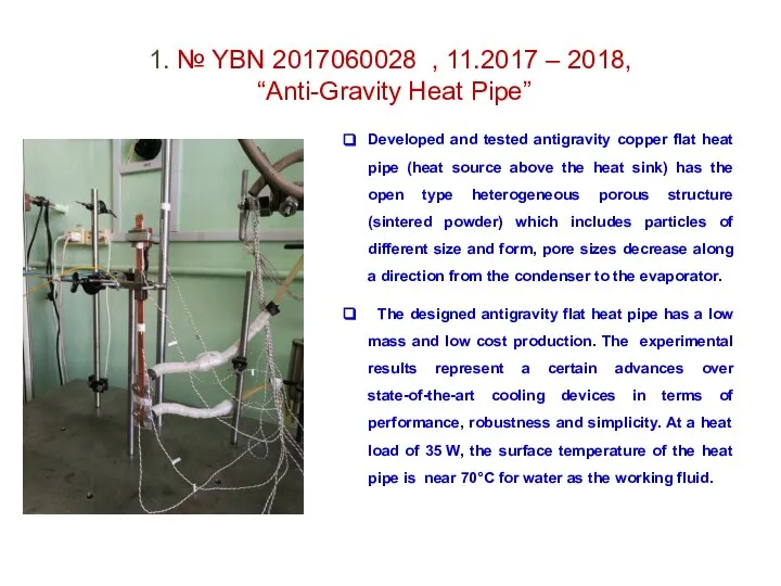
- 7. 1. № YBN 2017060028 , 11.2017 – 2018, “Anti-Gravity Heat Pipe” Developed and tested antigravity copper
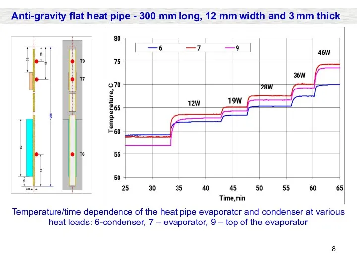
- 8. Temperature/time dependence of the heat pipe evaporator and condenser at various heat loads: 6-condenser, 7 –
- 9. 1. “Development, fabrication and research of compressible vapor chamber (CVC)”, 2018. 2. “To improve the thermal
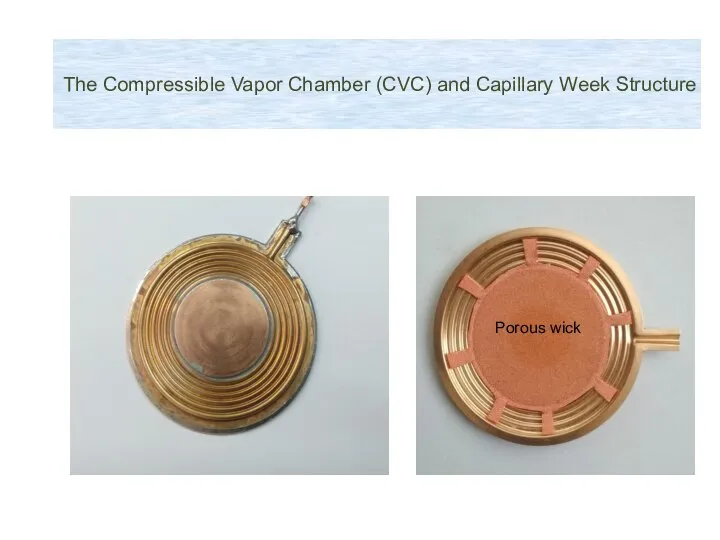
- 10. The Compressible Vapor Chamber (CVC) and Capillary Week Structure Porous wick
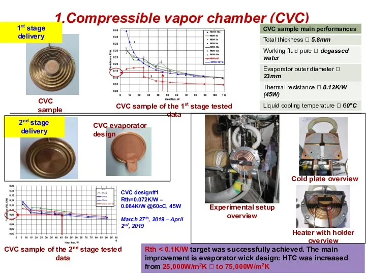
- 11. 1.Compressible vapor chamber (CVC) Rth CVC sample CVC sample of the 1st stage tested data Experimental
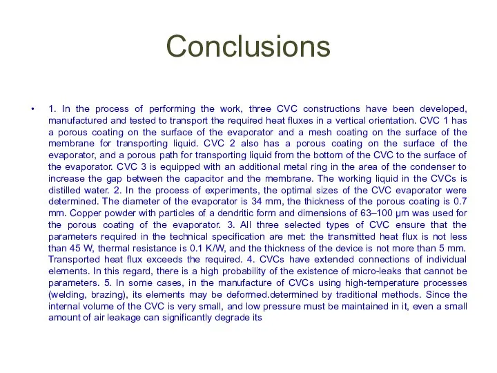
- 12. Conclusions 1. In the process of performing the work, three CVC constructions have been developed, manufactured
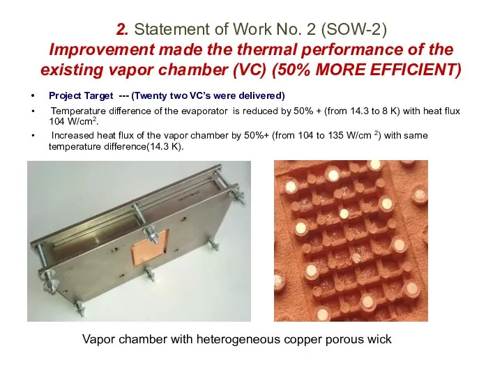
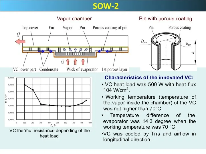
- 13. 2. Statement of Work No. 2 (SOW-2) Improvement made the thermal performance of the existing vapor
- 14. SOW-2 VC thermal resistance depending of the heat load Characteristics of the innovated VC: VC heat
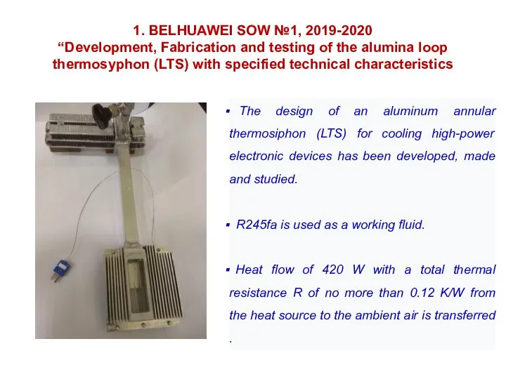
- 15. 1. BELHUAWEI SOW №1, 2019-2020 “Development, Fabrication and testing of the alumina loop thermosyphon (LTS) with
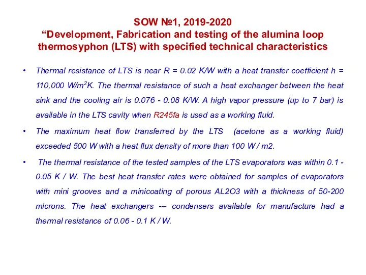
- 16. SOW №1, 2019-2020 “Development, Fabrication and testing of the alumina loop thermosyphon (LTS) with specified technical
- 18. Скачать презентацию
Слайд 3Boiling and condensation are the key heat-transfer modes with high heat transfer
Boiling and condensation are the key heat-transfer modes with high heat transfer
Слайд 4Part 1
Contracts:
Short Historical overeviews of the Porous media laboratory
Luikov HMTI NAN,
Part 1
Contracts:
Short Historical overeviews of the Porous media laboratory
Luikov HMTI NAN,
Слайд 5
1. № HTS-HMTI- 01, YB2014090048. 30.09.2014
“To research and develop the technology to
1. № HTS-HMTI- 01, YB2014090048. 30.09.2014
“To research and develop the technology to
Слайд 62.Contracts between BELHUAWEI (SOW) and Porous media Lab.,
Luikov Insitute, HMTI NAN
Luikov Insitute, HMTI NAN
Слайд 7
1. № YBN 2017060028 , 11.2017 – 2018, “Anti-Gravity Heat Pipe”
Developed and
1. № YBN 2017060028 , 11.2017 – 2018, “Anti-Gravity Heat Pipe”
Developed and
Слайд 8Temperature/time dependence of the heat pipe evaporator and condenser at various heat
Temperature/time dependence of the heat pipe evaporator and condenser at various heat
Слайд 91. “Development, fabrication and research of compressible vapor chamber (CVC)”, 2018.
2. “To
2. “To
Слайд 10The Compressible Vapor Chamber (CVC) and Capillary Week Structure
Porous wick
The Compressible Vapor Chamber (CVC) and Capillary Week Structure
Porous wick
Слайд 111.Compressible vapor chamber (CVC)
Rth < 0.1K/W target was successfully achieved. The main
1.Compressible vapor chamber (CVC)
Rth < 0.1K/W target was successfully achieved. The main
Слайд 12Conclusions
1. In the process of performing the work, three CVC constructions
Conclusions
1. In the process of performing the work, three CVC constructions
Слайд 13
2. Statement of Work No. 2 (SOW-2)
Improvement made the thermal performance of
2. Statement of Work No. 2 (SOW-2) Improvement made the thermal performance of
Слайд 14 SOW-2
VC thermal resistance depending of the heat load
Characteristics
SOW-2
VC thermal resistance depending of the heat load
Characteristics
Слайд 151. BELHUAWEI SOW №1, 2019-2020
“Development, Fabrication and testing of the alumina loop
1. BELHUAWEI SOW №1, 2019-2020 “Development, Fabrication and testing of the alumina loop
Слайд 16SOW №1, 2019-2020
“Development, Fabrication and testing of the alumina loop thermosyphon (LTS)
SOW №1, 2019-2020 “Development, Fabrication and testing of the alumina loop thermosyphon (LTS)
 Annoyance is visible in
 Разгадай ребус. Что обозначает это слово? СЕМЬЯ Группа родственников, живущих вместе. (Словарь С.И.Ожегова)
 Кошка
Кошка ГБОУ детский сад № 184
 Трагическая острота конфликта Катерины с «темным царством»
 Презентация на тему Я гражданин России
 SEM. Супер цена
 Работа тьютора по включению ребенка с РАС в образовательное пространство
 Опыт работы шмо классных руководителей
 Новый модельный ряд от ARISTONABS PRO ECO ЧИСТАЯ БЕЗОПАСНОСТЬ
 Территориально – производственная структура нефтяной промышленности РФ
 Организационная культура и этикет взаимоотношений
 Архитектура Владимиро-Суздальского княжества 10 класс
 Click to edit Master title style Click to edit Master subtitle style
  КАБИНЕТ ГЕОГРАФИИ МОУ «Средняя общеобразовательная школа №5 г.Нарьян-Мара»
 Страхование ответственности при осуществлении оценочной деятельности
 Государственное бюджетное общеобразовательное учреждение средняя общеобразовательная школа №661Приморского района Санкт-Пете
 Гимнастика.Климашевской Елизаветы
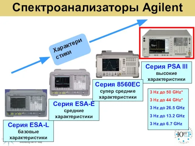 Спектроанализаторы Agilent
 Орфограммы в окончаниях
 Lexical Approach
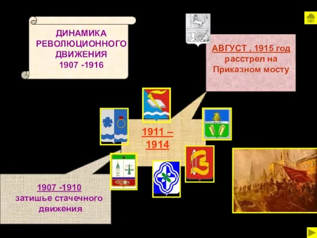 Динамика революционного движения 1907-1916
 Формирование у младших школьников правильной читательской деятельности
 Заседание Правления Российского союза промышленников и предпринимателей
 ТГП 1
ТГП 1 Тип губки
 Талисман компании ТЦ Пиплз парк
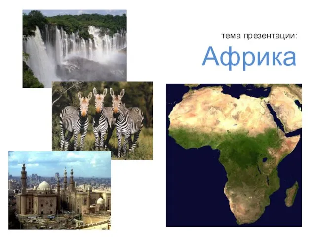 Презентация на тему Африка