- Hedrogen and Oxygen

Содержание
- 2. Introduction The paper presents the early published and the new results of investigation of the hydrogen
- 3. Outline 1. The experimental devices and methods 2. The hydrogen and oxygen trapping and retention in
- 4. The experimental devices and methods
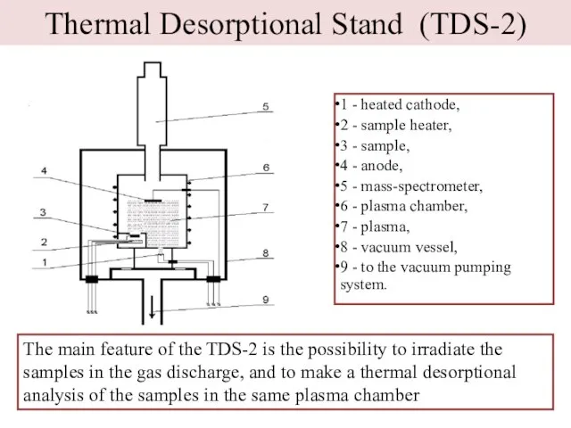
- 5. Thermal Desorptional Stand (TDS-2) 1 - heated cathode, 2 - sample heater, 3 - sample, 4
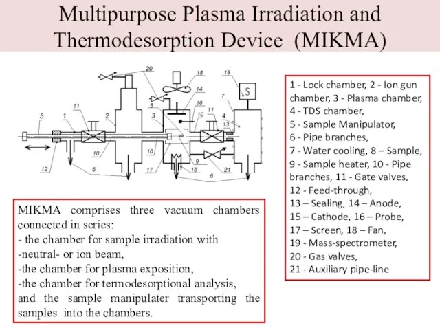
- 6. Multipurpose Plasma Irradiation and Thermodesorption Device (MIKMA) 1 - Lock chamber, 2 - Ion gun chamber,
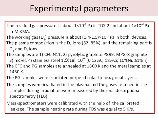
- 7. Experimental parameters Тhe residual gas pressure is about 1×10⁻³ Pa in TDS-2 and about 1×10⁻⁴ Pa
- 8. Hydrogen and oxygen trapping and retention in CFC and PG
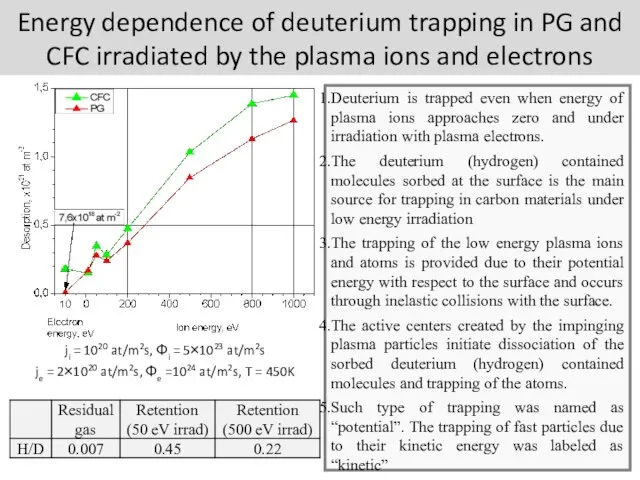
- 9. Energy dependence of deuterium trapping in PG and CFC irradiated by the plasma ions and electrons
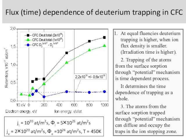
- 10. Flux (time) dependence of deuterium trapping in CFC ji = 1020 at/m2s, Φi = 5×10²³ at/m2s
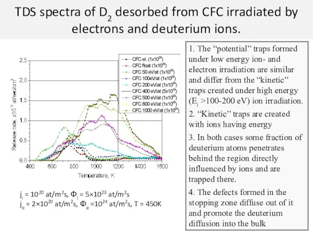
- 11. TDS spectra of D2 desorbed from CFC irradiated by electrons and deuterium ions. 1. The “potential”
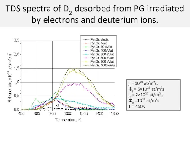
- 12. TDS spectra of D2 desorbed from PG irradiated by electrons and deuterium ions. ji = 1020
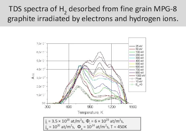
- 13. Спектры десорбции водорода из графита МПГ-8 облученного ионами различных энергий и электронами TDS spectra of H2
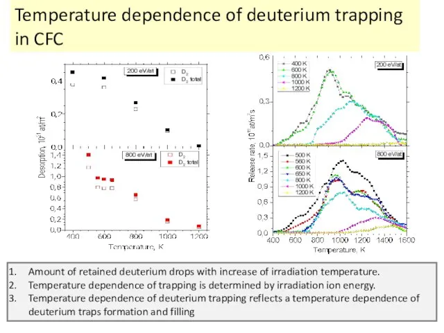
- 14. Temperature dependence of deuterium trapping in CFC Amount of retained deuterium drops with increase of irradiation
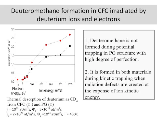
- 15. Deuteromethane formation in CFC irradiated by deuterium ions and electrons Thermal desorption of deuterium as CD4
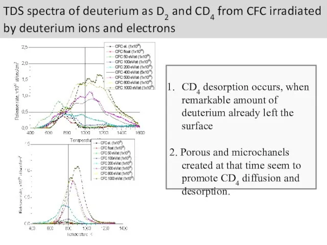
- 16. TDS spectra of deuterium as D2 and CD4 from CFC irradiated by deuterium ions and electrons
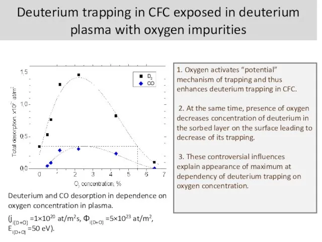
- 17. Deuterium trapping in CFC exposed in deuterium plasma with oxygen impurities Deuterium and CO desorption in
- 18. The hydrogen and oxygen trapping and retention in SS and nickel
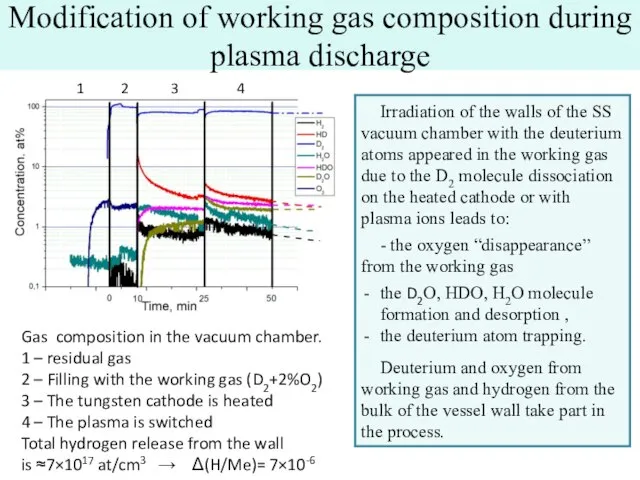
- 19. Modification of working gas composition during plasma discharge Irradiation of the walls of the SS vacuum
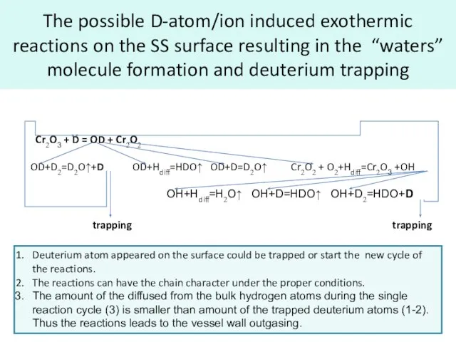
- 20. The possible D-atom/ion induced exothermic reactions on the SS surface resulting in the “waters” molecule formation
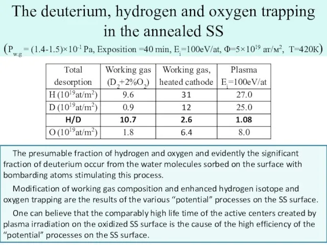
- 21. The deuterium, hydrogen and oxygen trapping in the annealed SS (Pw.g = (1.4-1.5)×10-1 Pa, Exposition =40
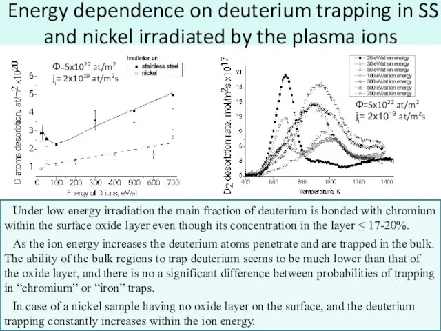
- 22. Energy dependence on deuterium trapping in SS and nickel irradiated by the plasma ions Under low
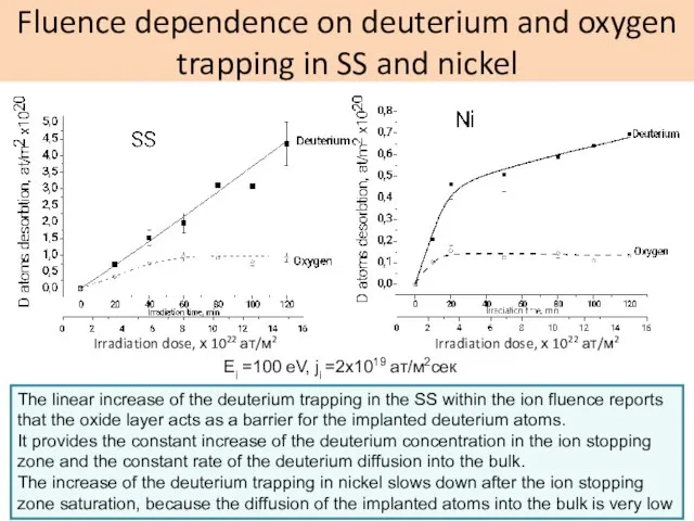
- 23. Fluence dependence on deuterium and oxygen trapping in SS and nickel Irradiation dose, х 1022 ат/м2
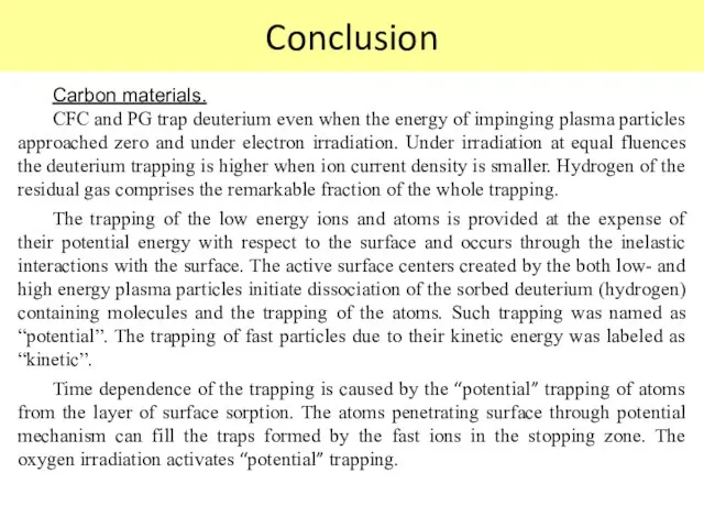
- 24. Conclusion Carbon materials. CFC and PG trap deuterium even when the energy of impinging plasma particles
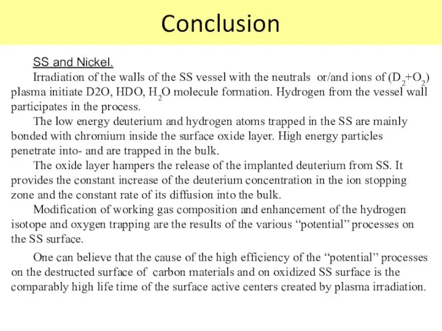
- 25. Conclusion SS and Nickel. Irradiation of the walls of the SS vessel with the neutrals or/and
- 27. Скачать презентацию
Слайд 3Outline
1. The experimental devices and methods
2. The hydrogen and oxygen trapping and
Outline
1. The experimental devices and methods
2. The hydrogen and oxygen trapping and
Слайд 4The experimental devices and methods
The experimental devices and methods
Слайд 5Thermal Desorptional Stand (TDS-2)
1 - heated cathode,
2 - sample heater,
3 -
Thermal Desorptional Stand (TDS-2)
1 - heated cathode,
2 - sample heater,
3 -
Слайд 6Multipurpose Plasma Irradiation and Thermodesorption Device (MIKMA)
1 - Lock chamber, 2 -
Multipurpose Plasma Irradiation and Thermodesorption Device (MIKMA)
1 - Lock chamber, 2 -
Слайд 7Experimental parameters
Тhe residual gas pressure is about 1×10⁻³ Pa in TDS-2 and
Experimental parameters
Тhe residual gas pressure is about 1×10⁻³ Pa in TDS-2 and
Слайд 8Hydrogen and oxygen trapping and retention in CFC and PG
Hydrogen and oxygen trapping and retention in CFC and PG
Слайд 9Energy dependence of deuterium trapping in PG and CFC irradiated by the
Energy dependence of deuterium trapping in PG and CFC irradiated by the
Слайд 10Flux (time) dependence of deuterium trapping in CFC
ji = 1020 at/m2s,
Flux (time) dependence of deuterium trapping in CFC
ji = 1020 at/m2s,
Слайд 11TDS spectra of D2 desorbed from CFC irradiated by electrons and deuterium
TDS spectra of D2 desorbed from CFC irradiated by electrons and deuterium
Слайд 12TDS spectra of D2 desorbed from PG irradiated by electrons and deuterium
TDS spectra of D2 desorbed from PG irradiated by electrons and deuterium
Слайд 13Спектры десорбции водорода из графита МПГ-8 облученного ионами различных энергий и электронами
TDS
Спектры десорбции водорода из графита МПГ-8 облученного ионами различных энергий и электронами
TDS
Слайд 14Temperature dependence of deuterium trapping in CFC
Amount of retained deuterium drops
Temperature dependence of deuterium trapping in CFC
Amount of retained deuterium drops
Слайд 15Deuteromethane formation in CFC irradiated by deuterium ions and electrons
Thermal desorption of
Deuteromethane formation in CFC irradiated by deuterium ions and electrons
Thermal desorption of
Слайд 16TDS spectra of deuterium as D2 and CD4 from CFC irradiated by
TDS spectra of deuterium as D2 and CD4 from CFC irradiated by
Слайд 17Deuterium trapping in CFC exposed in deuterium plasma with oxygen impurities
Deuterium and
Deuterium trapping in CFC exposed in deuterium plasma with oxygen impurities
Deuterium and
Слайд 18The hydrogen and oxygen trapping and retention in SS and nickel
The hydrogen and oxygen trapping and retention in SS and nickel

Слайд 19Modification of working gas composition during plasma discharge
Irradiation of the walls of
Modification of working gas composition during plasma discharge
Irradiation of the walls of
Слайд 20The possible D-atom/ion induced exothermic reactions on the SS surface resulting in
The possible D-atom/ion induced exothermic reactions on the SS surface resulting in
Слайд 21The deuterium, hydrogen and oxygen trapping in the annealed SS
(Pw.g =
The deuterium, hydrogen and oxygen trapping in the annealed SS (Pw.g =
Слайд 22Energy dependence on deuterium trapping in SS and nickel irradiated by the
Energy dependence on deuterium trapping in SS and nickel irradiated by the
Слайд 23Fluence dependence on deuterium and oxygen trapping in SS and nickel
Irradiation dose,
Fluence dependence on deuterium and oxygen trapping in SS and nickel
Irradiation dose,
Слайд 24Conclusion
Carbon materials.
CFC and PG trap deuterium even when the energy of impinging
Conclusion
Carbon materials.
CFC and PG trap deuterium even when the energy of impinging
Слайд 25Conclusion
SS and Nickel.
Irradiation of the walls of the SS vessel with the
Conclusion
SS and Nickel.
Irradiation of the walls of the SS vessel with the
 Презентация на тему Родовые окончания имен существительных
 Наследование групп крови
 Общие сведения о выпускаемой продукции
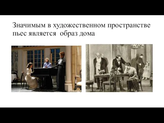 Организация пространства в пьесе Вишневый сад
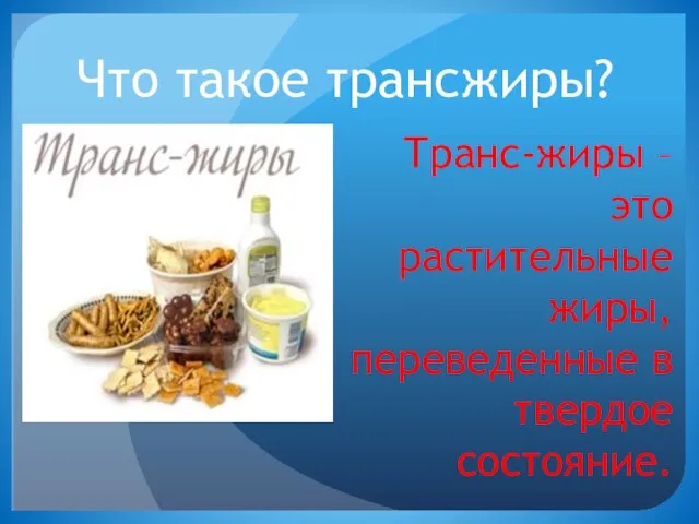 Гигиена питания: Что такое трансжиры?
 как стать личностью
 Phrasal Verbs
 Органическая химия
 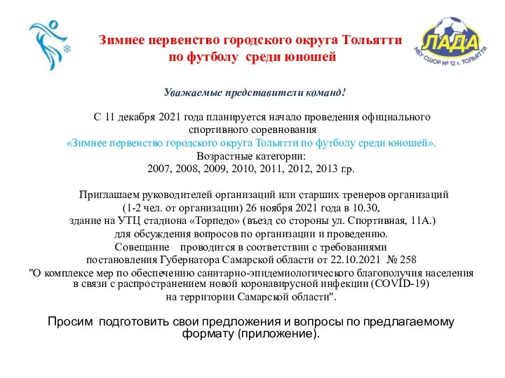 Зимнее первенство городского округа Тольятти по футболу среди юношей
 Спасатели
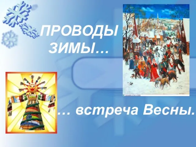 Проводы зимы
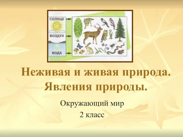 Неживая и живая природа
 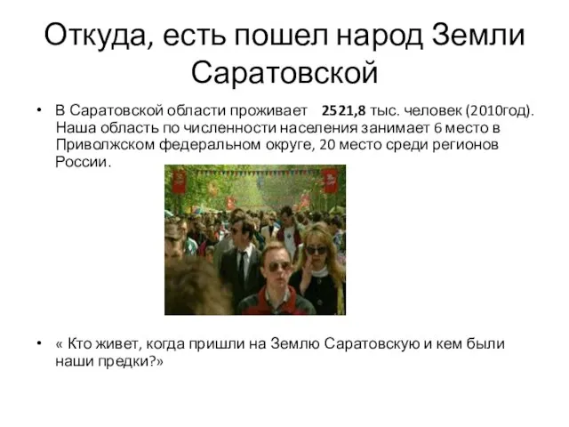 Из истории заселения Саратовского края
 Концепция трансформируемого автомобиля
 Автоматизация трудного звука Р
 Вода в жизни растений и животных
 Водные ресурсы России
 Урок-обобщение и систематизация изученногопо орфографии и пунктуации (урок-практикум).
 Презентация на тему От чтения к скорочтению
 2009.1
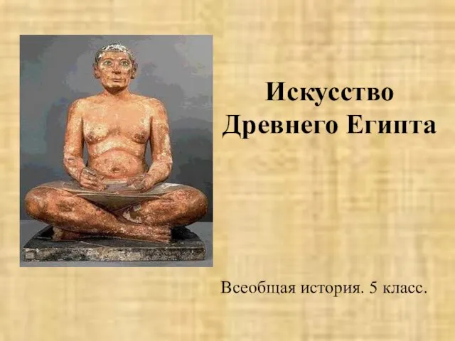 Искусство Древнего Египта 5 класс
  Диаграмма
 Выборы на Украине 2019 года
 КОГРА
КОГРА Презентация на тему Как вести себя в театре
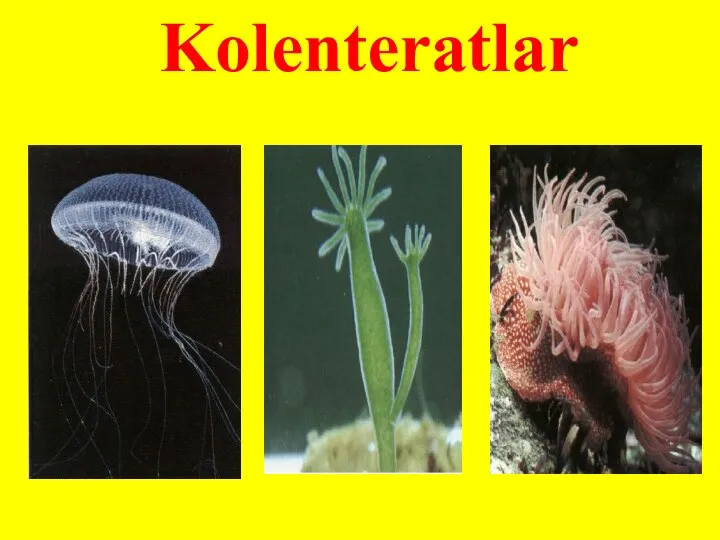 Gidra
Gidra Царство Животны. Тип Моллюски. Классы - Брюхоногие Двустворчатые Головоногие
 Память и внимание