- Telecom Implementation Guideline-Flexi Multi Radio Site Solutions

Содержание
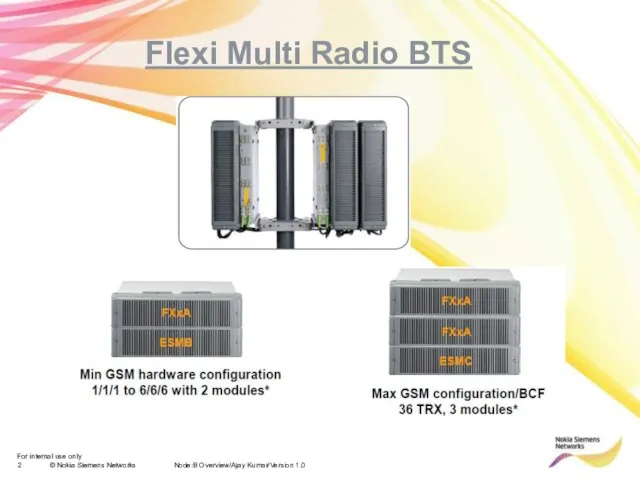
- 2. Node:B Overview/Ajay Kumar/Version 1.0 Flexi Multi Radio BTS
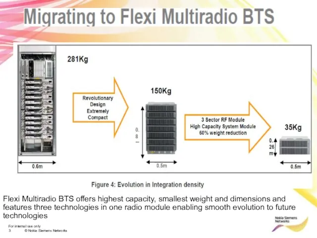
- 3. Flexi Multiradio BTS offers highest capacity, smallest weight and dimensions and features three technologies in one
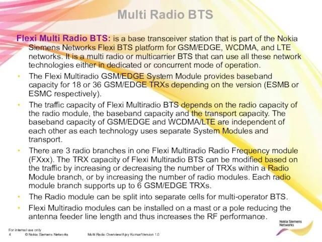
- 4. Multi Radio Overview/Ajay Kumar/Version 1.0 Multi Radio BTS Flexi Multi Radio BTS: is a base transceiver
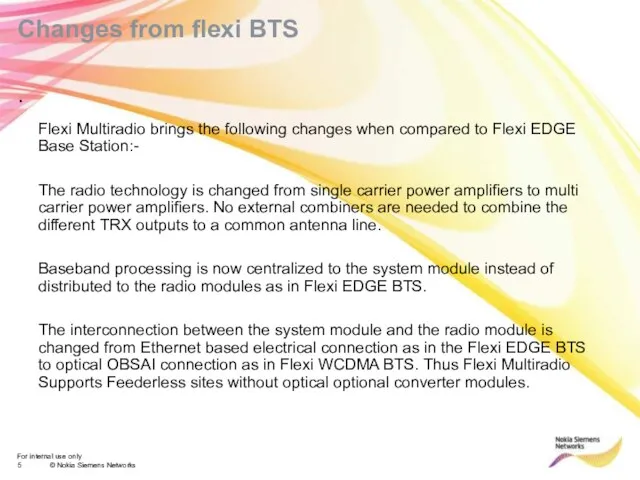
- 5. Changes from flexi BTS Flexi Multiradio brings the following changes when compared to Flexi EDGE Base
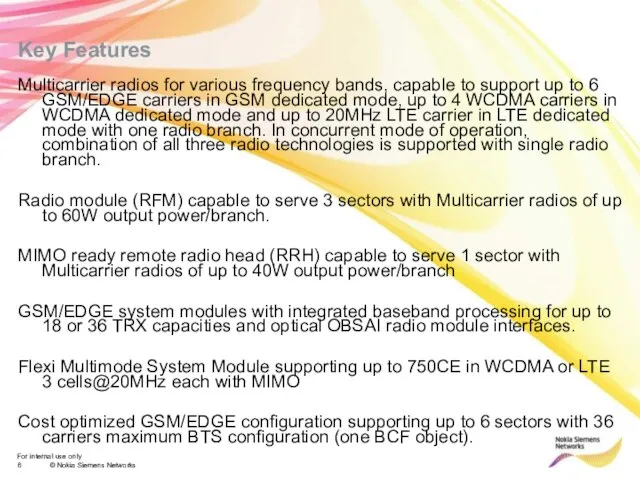
- 6. Key Features Multicarrier radios for various frequency bands, capable to support up to 6 GSM/EDGE carriers
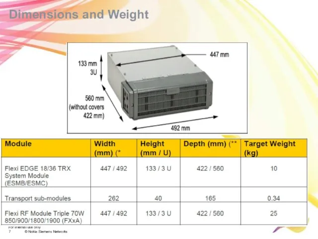
- 7. Dimensions and Weight
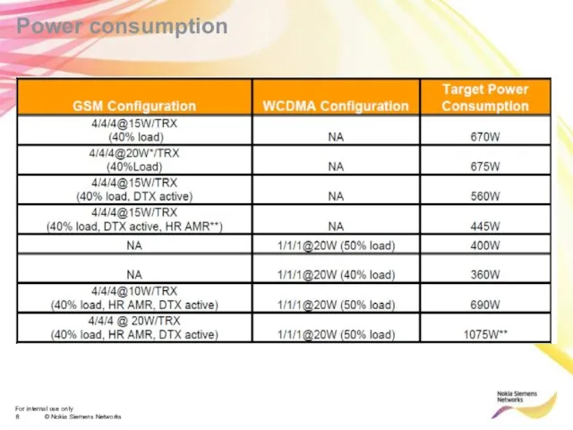
- 8. Power consumption
- 9. Multi Radio Overview/Ajay Kumar/Version 1.0 System Module
- 10. Multi Radio Overview/Ajay Kumar/Version 1.0 System Module GSM/EDGE BTS Operation and Maintenance Abis interfacing Open Base
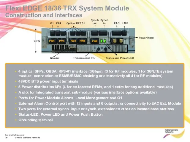
- 11. Flexi EDGE 18/36 TRX System Module Construction and Interfaces 4 optical SFPs. OBSAI RP3-01 interface (3Gbps).
- 12. Flexi EDGE 18/36 TRX System Module ESMB/ESMC has an integrated transport unit which provides the physical
- 13. Flexi EDGE 18/36 TRX System Module The operating power can be supplied to the radios from
- 14. Multi Radio Overview/Ajay Kumar/Version 1.0 ESMB/C Module Interface The System Module is equipped with the following
- 15. Multi Radio Overview/Ajay Kumar/Version 1.0 RF Module
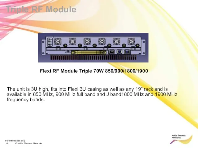
- 16. Triple RF Module Flexi RF Module Triple 70W 850/900/1800/1900 The unit is 3U high, fits into
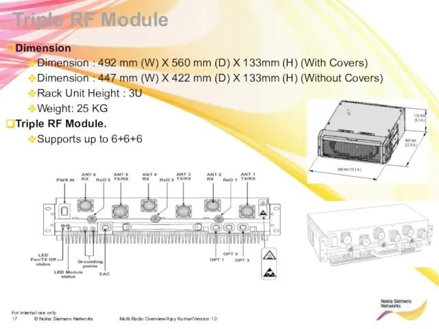
- 17. Multi Radio Overview/Ajay Kumar/Version 1.0 Triple RF Module Dimension Dimension : 492 mm (W) X 560
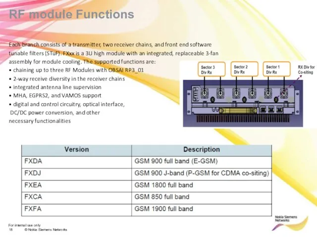
- 18. RF module Functions Each branch consists of a transmitter, two receiver chains, and front end software
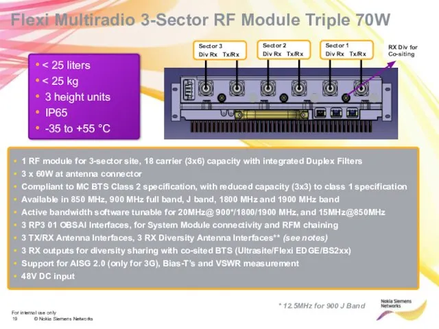
- 19. 3 height units IP65 -35 to +55 °C Flexi Multiradio 3-Sector RF Module Triple 70W 1
- 20. RF Module power requirements and output power Multi Radio Overview/Ajay Kumar/Version 1.0
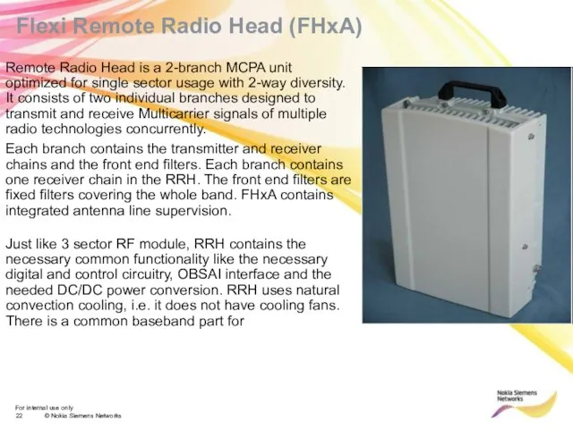
- 22. Flexi Remote Radio Head (FHxA) Remote Radio Head is a 2-branch MCPA unit optimized for single
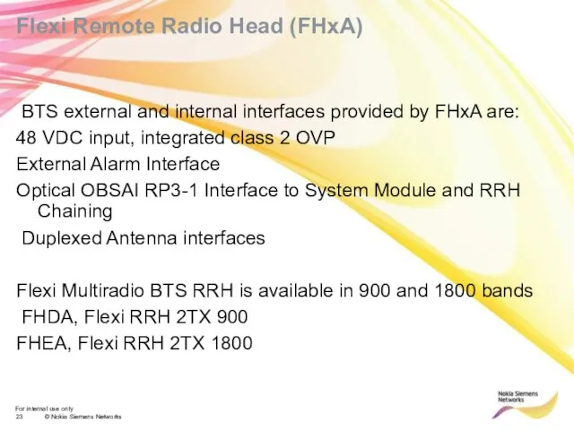
- 23. Flexi Remote Radio Head (FHxA) BTS external and internal interfaces provided by FHxA are: 48 VDC
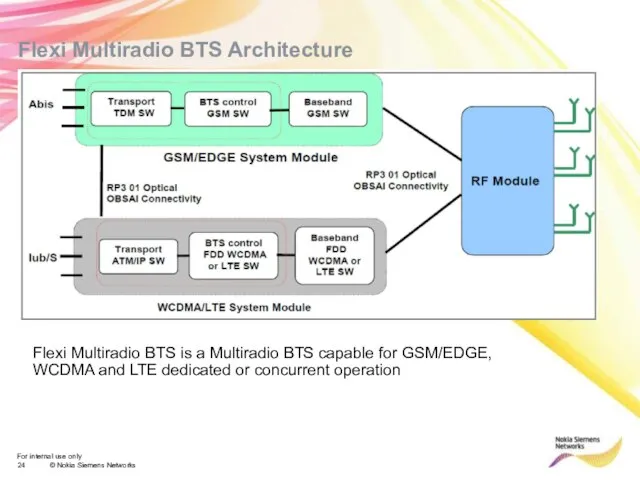
- 24. Flexi Multiradio BTS Architecture Flexi Multiradio BTS is a Multiradio BTS capable for GSM/EDGE, WCDMA and
- 25. Configurations RP3 Configurations Optical OBSAI RP3-1 is used for the inter connection between the system module
- 26. Configurations System module interconnection It is possible to inter connect the GSM/EDGE and the WCDMA/LTE system
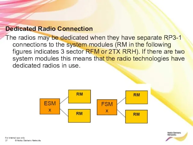
- 27. Dedicated Radio Connection The radios may be dedicated when they have separate RP3-1 connections to the
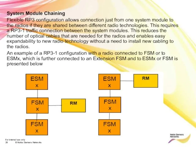
- 28. System Module Chaining Flexible RP3 configuration allows connection just from one system module to the radios
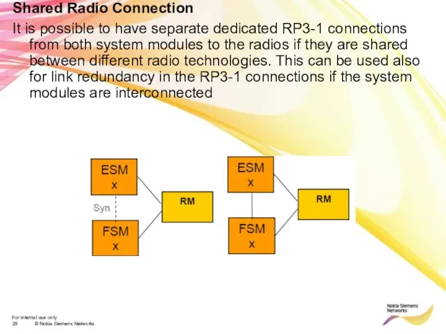
- 29. Shared Radio Connection It is possible to have separate dedicated RP3-1 connections from both system modules
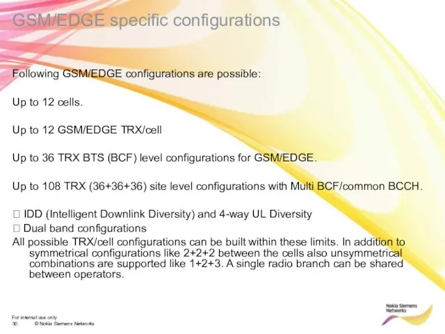
- 30. GSM/EDGE specific configurations Following GSM/EDGE configurations are possible: Up to 12 cells. Up to 12 GSM/EDGE
- 31. WCDMA/LTE specific configurations The existing WCDMA and LTE configurations are supported. WCDMA: Up to 4+4+4 (20MHz)
- 32. BTS Synchronization and transport solutions The Flexi Multiradio BTS transport solution is based on the Flexi
- 33. BTS Synchronization he Flexi Multiradio BTS is able to take its reference frequency from any of
- 34. ESMx integrated transmission he Flexi Multiradio BTS GSM/EDGE system module uses the same transport options as
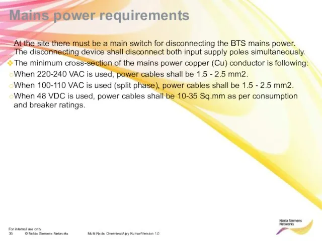
- 35. Mains power requirements Multi Radio Overview/Ajay Kumar/Version 1.0 At the site there must be a main
- 36. Presentation / Author / Date NSN Multi Radio Implementation Solutions
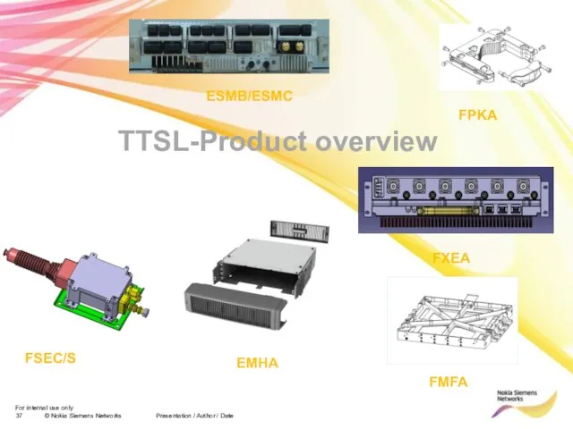
- 37. Presentation / Author / Date TTSL-Product overview ESMB/ESMC FXEA FPKA FMFA FSEC/S EMHA
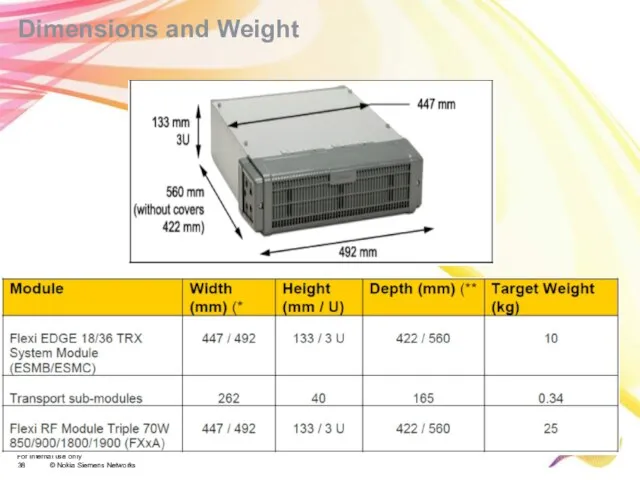
- 38. Dimensions and Weight
- 39. Flexi EDGE 18/36 TRX System Module Construction and Interfaces 4 optical SFPs. OBSAI RP3-01 interface (3Gbps).
- 40. 3 height units IP65 -35 to +55 °C Flexi Multi Radio 3-Sector RF Module Triple 70W
- 41. / FSES is an over voltage protection device. FSES is used to protect Flexi Units in
- 42. Flexi Multi Radio BTS optional items (3/5) Cabinets and cabinet options: 470142A FCOA Flexi Cabinet Outdoor
- 43. Multi Radio BTS Solution Concept Presentation / Author / Date
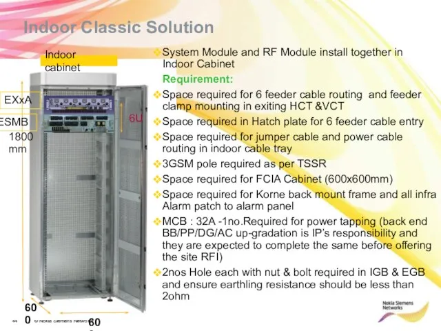
- 44. Indoor cabinet 1800mm 600 600 Indoor Classic Solution System Module and RF Module install together in
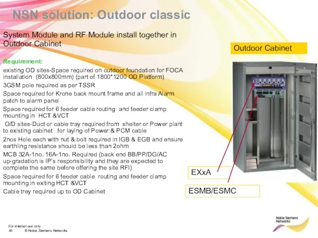
- 45. NSN solution: Outdoor classic System Module and RF Module install together in Outdoor Cabinet Requirement: existing
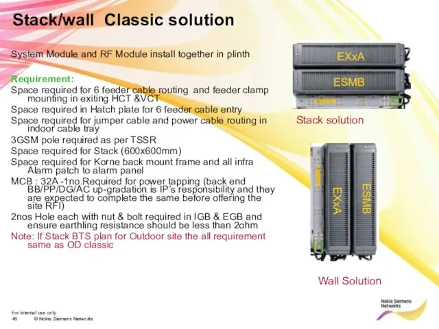
- 46. Stack/wall Classic solution System Module and RF Module install together in plinth Requirement: Space required for
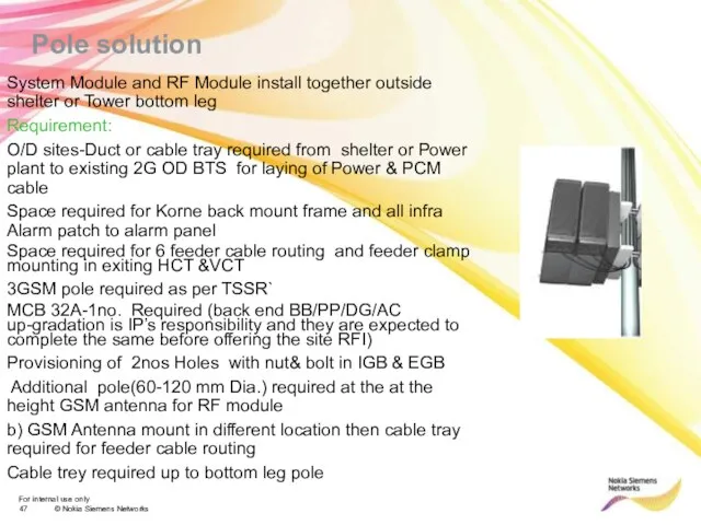
- 47. Pole solution System Module and RF Module install together outside shelter or Tower bottom leg Requirement:
- 48. Indoor Distributed Solution Optical cable Requirement: 3GSM pole required as per TSSR Space required for FCIA
- 49. System Module install in OD cabinet and RF Module on Tower Pole Requirement: existing OD sites-Space
- 50. System Module install in Plinth and RF Module on Tower Pole Requirement: 3GSM pole required as
- 51. Pole Distributed Solution System Module outside shelter or Tower bottom leg and RF Module install on
- 52. Site Requirements-BTS Grounding Main grounding (earthling) is tested within last 3 months. The earthling (grounding) resistance
- 54. Скачать презентацию
Слайд 3Flexi Multiradio BTS offers highest capacity, smallest weight and dimensions and features
Flexi Multiradio BTS offers highest capacity, smallest weight and dimensions and features
Слайд 4Multi Radio Overview/Ajay Kumar/Version 1.0
Multi Radio BTS
Flexi Multi Radio BTS:
Multi Radio Overview/Ajay Kumar/Version 1.0
Multi Radio BTS
Flexi Multi Radio BTS:
Слайд 5Changes from flexi BTS
Flexi Multiradio brings the following changes when compared to
Changes from flexi BTS
Flexi Multiradio brings the following changes when compared to
Слайд 6
Key Features
Multicarrier radios for various frequency bands, capable to support up
Key Features
Multicarrier radios for various frequency bands, capable to support up
Слайд 7Dimensions and Weight
Dimensions and Weight
Слайд 8Power consumption
Power consumption
Слайд 9Multi Radio Overview/Ajay Kumar/Version 1.0
System Module
Multi Radio Overview/Ajay Kumar/Version 1.0
System Module
Слайд 10Multi Radio Overview/Ajay Kumar/Version 1.0
System Module
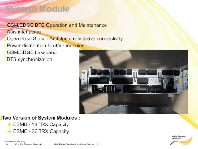
GSM/EDGE BTS Operation and Maintenance
Abis interfacing
Open
Multi Radio Overview/Ajay Kumar/Version 1.0
System Module
GSM/EDGE BTS Operation and Maintenance
Abis interfacing
Open
Слайд 11Flexi EDGE 18/36 TRX System Module
Construction and Interfaces
4 optical SFPs. OBSAI RP3-01
Flexi EDGE 18/36 TRX System Module
Construction and Interfaces
4 optical SFPs. OBSAI RP3-01

Слайд 12
Flexi EDGE 18/36 TRX System Module
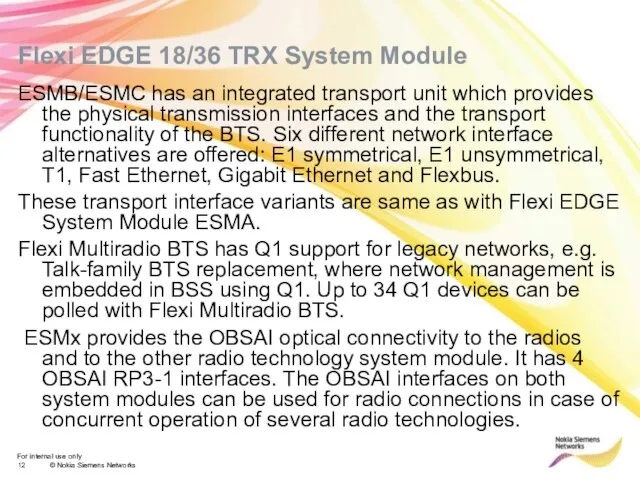
ESMB/ESMC has an integrated transport unit
Flexi EDGE 18/36 TRX System Module
ESMB/ESMC has an integrated transport unit
Слайд 13
Flexi EDGE 18/36 TRX System Module
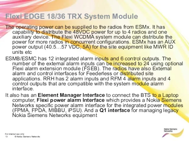
The operating power can be supplied
Flexi EDGE 18/36 TRX System Module
The operating power can be supplied
Слайд 14Multi Radio Overview/Ajay Kumar/Version 1.0
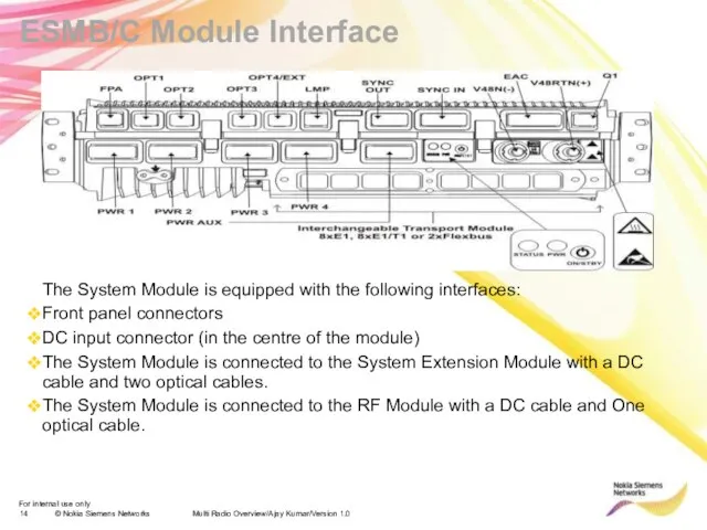
ESMB/C Module Interface
The System Module is equipped with
Multi Radio Overview/Ajay Kumar/Version 1.0
ESMB/C Module Interface
The System Module is equipped with
Слайд 15Multi Radio Overview/Ajay Kumar/Version 1.0
RF Module
Multi Radio Overview/Ajay Kumar/Version 1.0
RF Module
Слайд 16Triple RF Module
Flexi RF Module Triple 70W 850/900/1800/1900
The unit is 3U
Triple RF Module
Flexi RF Module Triple 70W 850/900/1800/1900
The unit is 3U
Слайд 17Multi Radio Overview/Ajay Kumar/Version 1.0
Triple RF Module
Dimension
Dimension : 492 mm (W) X
Multi Radio Overview/Ajay Kumar/Version 1.0
Triple RF Module
Dimension
Dimension : 492 mm (W) X
Слайд 18RF module Functions
Each branch consists of a transmitter, two receiver chains, and
RF module Functions
Each branch consists of a transmitter, two receiver chains, and
Слайд 19< 25 liters
< 25 kg
3 height units
IP65
-35 to +55
< 25 liters
< 25 kg
3 height units
IP65
-35 to +55
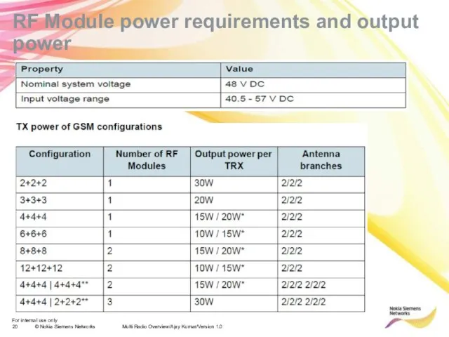
Слайд 20RF Module power requirements and output power
Multi Radio Overview/Ajay Kumar/Version 1.0
RF Module power requirements and output power
Multi Radio Overview/Ajay Kumar/Version 1.0
Слайд 22Flexi Remote Radio Head (FHxA)
Remote Radio Head is a 2-branch MCPA
Flexi Remote Radio Head (FHxA)
Remote Radio Head is a 2-branch MCPA
Слайд 23Flexi Remote Radio Head (FHxA)
BTS external and internal interfaces provided by
Flexi Remote Radio Head (FHxA)
BTS external and internal interfaces provided by
Слайд 24
Flexi Multiradio BTS Architecture
Flexi Multiradio BTS is a Multiradio BTS capable
Flexi Multiradio BTS Architecture
Flexi Multiradio BTS is a Multiradio BTS capable
Слайд 25Configurations
RP3 Configurations
Optical OBSAI RP3-1 is used for the inter connection
Configurations
RP3 Configurations
Optical OBSAI RP3-1 is used for the inter connection
Слайд 26Configurations
System module interconnection
It is possible to inter connect the GSM/EDGE and
Configurations
System module interconnection
It is possible to inter connect the GSM/EDGE and
Слайд 27Dedicated Radio Connection
The radios may be dedicated when they have separate
Dedicated Radio Connection
The radios may be dedicated when they have separate
Слайд 28System Module Chaining
Flexible RP3 configuration allows connection just from one system
System Module Chaining
Flexible RP3 configuration allows connection just from one system
Слайд 29Shared Radio Connection
It is possible to have separate dedicated RP3-1 connections
Shared Radio Connection
It is possible to have separate dedicated RP3-1 connections
Слайд 30GSM/EDGE specific configurations
Following GSM/EDGE configurations are possible:
Up to 12 cells.
Up
GSM/EDGE specific configurations
Following GSM/EDGE configurations are possible:
Up to 12 cells.
Up
Слайд 31
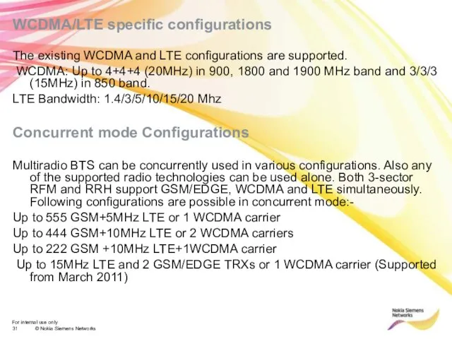
WCDMA/LTE specific configurations
The existing WCDMA and LTE configurations are supported.
WCDMA/LTE specific configurations
The existing WCDMA and LTE configurations are supported.
Слайд 32BTS Synchronization and transport solutions
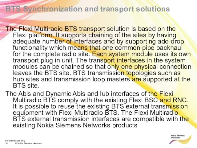
The Flexi Multiradio BTS transport solution is
BTS Synchronization and transport solutions
The Flexi Multiradio BTS transport solution is
Слайд 33BTS Synchronization
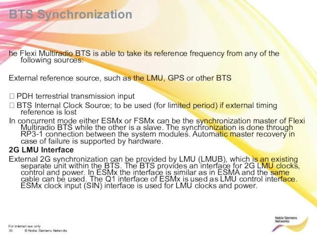
he Flexi Multiradio BTS is able to take its reference
BTS Synchronization
he Flexi Multiradio BTS is able to take its reference
Слайд 34
ESMx integrated transmission
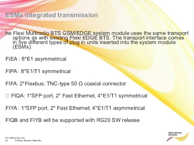
he Flexi Multiradio BTS GSM/EDGE system module uses the
ESMx integrated transmission
he Flexi Multiradio BTS GSM/EDGE system module uses the
Слайд 35Mains power requirements
Multi Radio Overview/Ajay Kumar/Version 1.0
At the site there must be
Mains power requirements
Multi Radio Overview/Ajay Kumar/Version 1.0
At the site there must be
Слайд 36Presentation / Author / Date
NSN Multi Radio Implementation Solutions
Presentation / Author / Date
NSN Multi Radio Implementation Solutions
Слайд 37Presentation / Author / Date
TTSL-Product overview
ESMB/ESMC
FXEA
FPKA
FMFA
FSEC/S
EMHA
Presentation / Author / Date
TTSL-Product overview
ESMB/ESMC
FXEA
FPKA
FMFA
FSEC/S
EMHA
Слайд 38Dimensions and Weight
Dimensions and Weight
Слайд 39Flexi EDGE 18/36 TRX System Module
Construction and Interfaces
4 optical SFPs. OBSAI RP3-01
Flexi EDGE 18/36 TRX System Module
Construction and Interfaces
4 optical SFPs. OBSAI RP3-01
Слайд 40< 25 liters
< 25 kg
3 height units
IP65
-35 to +55
< 25 liters
< 25 kg
3 height units
IP65
-35 to +55

Слайд 41 /
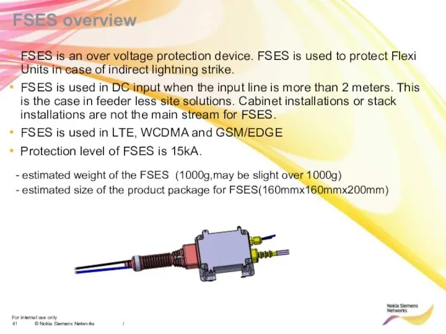
FSES is an over voltage protection device. FSES is used
/
FSES is an over voltage protection device. FSES is used
Слайд 42Flexi Multi Radio BTS optional items (3/5)
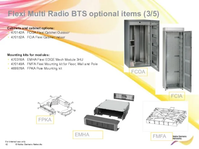
Cabinets and cabinet options:
470142A FCOA Flexi Cabinet
Flexi Multi Radio BTS optional items (3/5)
Cabinets and cabinet options:
470142A FCOA Flexi Cabinet
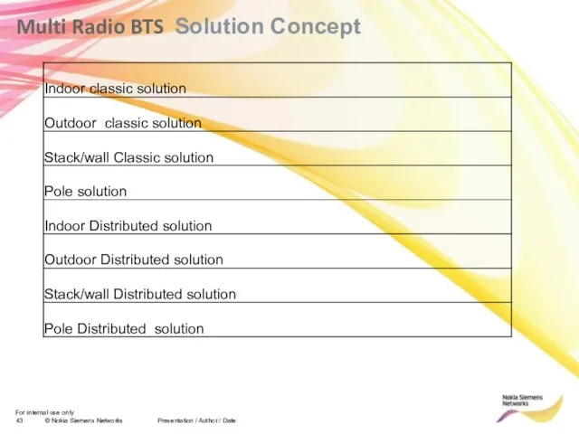
Слайд 43Multi Radio BTS Solution Concept
Presentation / Author / Date
Multi Radio BTS Solution Concept
Presentation / Author / Date
Слайд 44Indoor cabinet
1800mm
600
600
Indoor Classic Solution
System Module and RF Module install together in
Indoor cabinet
1800mm
600
600
Indoor Classic Solution
System Module and RF Module install together in
Слайд 45 NSN solution: Outdoor classic
System Module and RF Module install together in
NSN solution: Outdoor classic
System Module and RF Module install together in
Слайд 46Stack/wall Classic solution
System Module and RF Module install together in plinth
Stack/wall Classic solution
System Module and RF Module install together in plinth
Слайд 47Pole solution
System Module and RF Module install together outside shelter or Tower
Pole solution
System Module and RF Module install together outside shelter or Tower
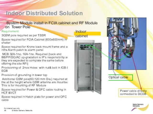
Слайд 48 Indoor Distributed Solution
Optical cable
Requirement:
3GSM pole required as per TSSR
Space required
Indoor Distributed Solution
Optical cable
Requirement:
3GSM pole required as per TSSR
Space required
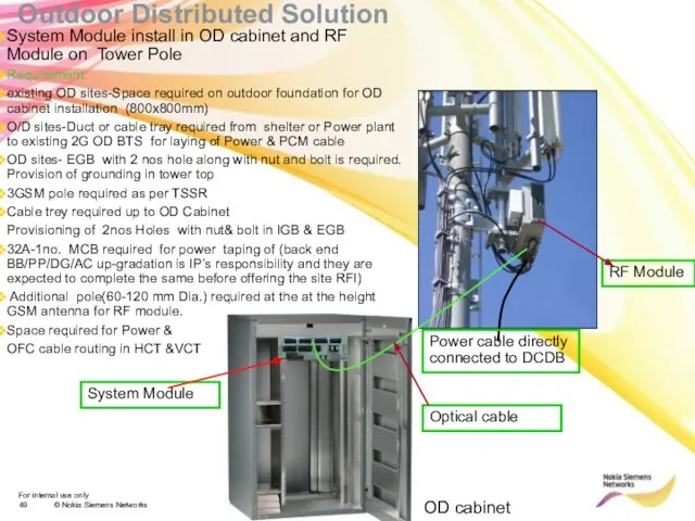
Слайд 49System Module install in OD cabinet and RF Module on Tower Pole
Requirement:
existing
System Module install in OD cabinet and RF Module on Tower Pole
Requirement:
existing
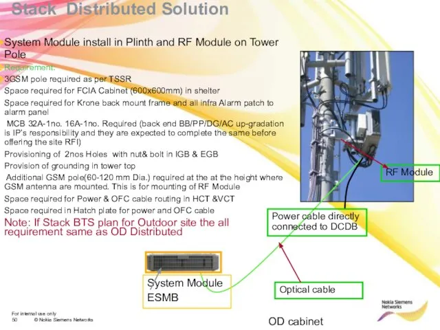
Слайд 50System Module install in Plinth and RF Module on Tower Pole
Requirement:
3GSM
Requirement:
3GSM
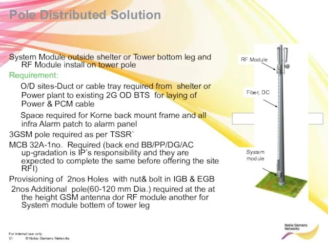
Слайд 51Pole Distributed Solution
System Module outside shelter or Tower bottom leg and RF
Pole Distributed Solution
System Module outside shelter or Tower bottom leg and RF
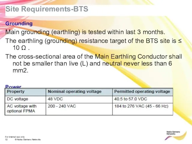
Слайд 52Site Requirements-BTS
Grounding
Main grounding (earthling) is tested within last 3 months.
The earthling (grounding)
Site Requirements-BTS
Grounding
Main grounding (earthling) is tested within last 3 months.
The earthling (grounding)
 С чего начинается Родина
 Правила склонения числительных
 Фёдор Михайлович Достоевский(1821-1881)
 Фигуры вращения
 Воспитательная работа и
 Каталог №6 Beauty Awards
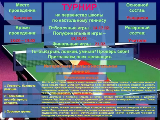 Турнир по теннису
 Составление портрета хитрого человека в художественном стиле.
 Презентация
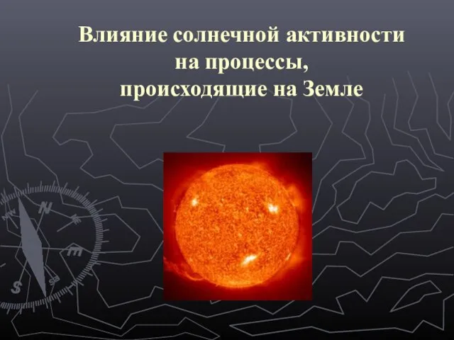 Презентация на тему Влияние солнечной активности на процессы,происходящие на Земле
 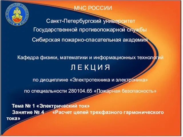 Электрический ток
  English Alphabet - презентация для начальной школы_
 Питер Пауль Рубенс. Библейские темы
 Времена года. Сезоны года
 Презентация на тему СКАЗКА «Двенадцать месяцев» С. Маршак
  Задача о снабжении
 Гражданская война и иностранная военная интервенция. 1918-1922гг
 Интерактивтік модульдік оқыту технологиясы арқылы оқушылардың шығармашылығын дамытудың жүйесі
 Способы защиты прав потребителей
 Презентация на тему Викторина по сказке
  Роль взаимоотношений подростков в формировании репродуктивной функции
 Тинькофф. 4 день
 Рисунок скелета человека
 Дублин. Ирландия - Dublin
 Конкур
 Эпоха Императора Николая II
 Тест по пьесе А.Вампилова «Старший сын»
 ПРОЕКТ «Профессиональный успех»