- Two Devices for HINS Robyn Madrak Accelerator Physics Center (APC)

Содержание
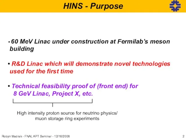
- 2. HINS - Purpose Robyn Madrak - FNAL APT Seminar - 12/16/2008 60 MeV Linac under construction
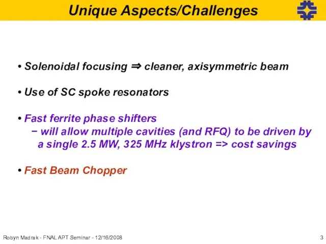
- 3. Unique Aspects/Challenges Solenoidal focusing ⇒ cleaner, axisymmetric beam Use of SC spoke resonators Fast ferrite phase
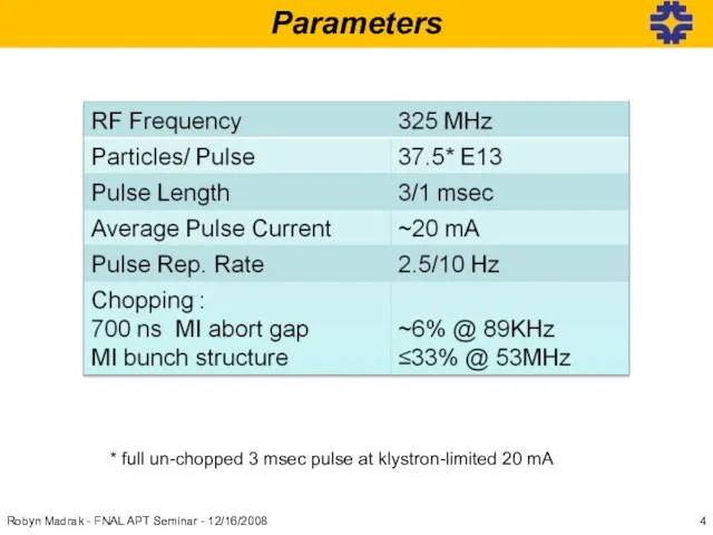
- 4. Robyn Madrak - FNAL APT Seminar - 12/16/2008 Parameters * full un-chopped 3 msec pulse at
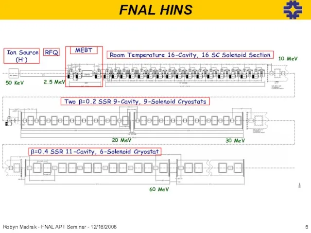
- 5. FNAL HINS Robyn Madrak - FNAL APT Seminar - 12/16/2008
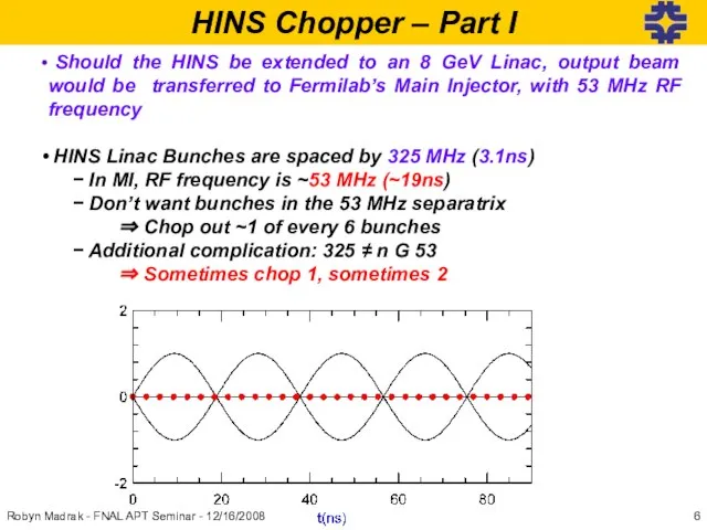
- 6. HINS Chopper – Part I Should the HINS be extended to an 8 GeV Linac, output
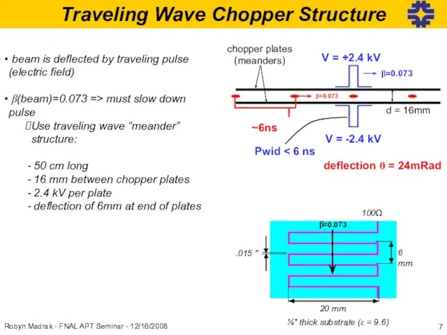
- 7. Traveling Wave Chopper Structure beam is deflected by traveling pulse (electric field) β(beam)=0.073 => must slow
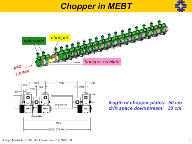
- 8. Chopper in MEBT length of chopper plates: 50 cm drift space downstream: 30 cm Robyn Madrak
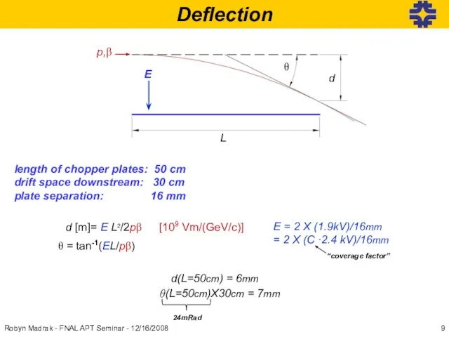
- 9. Deflection length of chopper plates: 50 cm drift space downstream: 30 cm plate separation: 16 mm
- 10. Pulser Development Robyn Madrak - FNAL APT Seminar - 12/16/2008 We need Two pulsers to drive
- 11. Similar Choppers CERN-SPL LANL-SNS
- 12. Combining lower voltage pulses? scope: sees ¼ of ~120V signal (25Ω/100Ω) Fet A (~60V) Fet B
- 13. Kentech 500V Pulser pulse control cards PSU pulse cards trigger and power dist cards output before
- 14. ~520 V pulse 5.5 ns 1 ms of pulses @ 53 MHz 3 ms of pulses
- 15. Pulser output 200V/div 5ns/div 3ms burst 200V/div 400μs/div 1.2 kV Pulser Nov ‘07 Robyn Madrak -
- 16. Kentech Pulsers 500 V Pulser was a success Subsequent 1.2 kV pulser was a success Plan:
- 17. Microstrips in General phase velocity and impedance are determined by effective dielectric constant: Delay time (β)
- 18. FNAL Fabricated Meanders We have pursued the following: Use double meander design with air gap between
- 19. Chopper Meanders Important Aspects Material: Outgassing ? Impedance (avoid reflections) Delay time (match beam β) Pulse
- 20. Meander Substrate Meander traces are generated by routing out traces on Rogers TMM10i, Cu clad Cheaper,
- 21. Double Meander, Impedance Impedance measurements from 1 – 500 MHz Robyn Madrak - FNAL APT Seminar
- 22. Double Meander, Delay Robyn Madrak - FNAL APT Seminar - 12/16/2008 Want β = 0.073 to
- 23. Single Meanders: Impedance and Delay Meander 1: 95 Ω @~100 MHz Meander 2: 100.5 Ω @~325
- 24. Dispersion input pulse beginning half way end single meander 2 single meander 1 “low dispersion” input
- 25. Coverage Factor The electric field between the chopper plates is less than that for a structure
- 26. Coverage Factor Measurements High frequency probe Tip is at top ground plane xy stage for position
- 27. input pulse @ end @end Coverage Factor Normalization Normalize to stripline with wide trace Use geometry
- 28. All Measured Coverage Factors Robyn Madrak - FNAL APT Seminar - 12/16/2008
- 29. Position Dependence beam RMS size 100% x Robyn Madrak - FNAL APT Seminar - 12/16/2008 20mm
- 30. 3 ms pulse combined output input 50Ω cable V1→50Ω V1→50Ω 50Ω cable MN60 ferrite: three 11’’
- 31. input ferrite 46 turns of ⅜″ superflex around five 1″ MN60 cores 1700 V →100 Ω
- 32. Heating in Meander Current in meander will be 2.4 kV/100 Ω = 24 A Need to
- 33. Chopper: Summary We have built prototypes for the necessary components for the chopper: the pulser, meander
- 34. Aside: Application of Chopper R&D to the current accelerator Initially explored the option of using a
- 35. Combining three DEI FETs from DEI/IXYS RF Use the same scheme as HINS pulser, combining three
- 36. Plates: 0.9″ spacing W1 Notching Plates in 750 keV line (H-)
- 37. In Linac after tank 2 ΔV plates = 2.9 kV ~100 ns wide notch 50 ns/div
- 38. Robyn Madrak - FNAL APT Seminar - 12/16/2008 Part II – Vector Modulators
- 39. HINS 325 MHz RF Pulse Transformer& Oil Tank IGBT Switch & Bouncer CAP BANK 10 kV
- 40. How it Works In a coaxial line filled with some dielectric (ε,μ) v = c/√εμ We
- 41. Robyn Madrak - FNAL APT Seminar - 12/16/2008 Operates in full reflection mode (end is shorted)
- 42. Modulates phase and amplitude independently: With ΔΦ = (Δφ2 - Δφ3)/2 Φ = (Δφ2 + Δφ3)/2
- 43. Two Phase Shifter Types For Cavities (~75 kW): 1.5″ OD X 0.65″ ID X 5″ long
- 44. Shifter Design Details Center conductor: shrink fit during assembly Use quarter wave matching section (for 50Ω)
- 45. Other VM Parts hybrid for 1⅝ vm: Dielectric circulator for 1⅝ vm: Ferrit-Quasar circulator load: 5kw
- 46. useful phase shift range ~120 deg. (loss Gyromagnetic resonance (lossy) @ 2.8 MHz/Oe Phase vs. Applied
- 47. Small Signal Frequency Response Open loop bandwidth: 15 kHz > 35 kHz w/feedback Response (mixer) solenoid
- 48. Slew Rate Phase Shifter Slew Rate: (above resonance) 6 deg/μs Current risetime limited by supply output,
- 49. Robyn Madrak - FNAL APT Seminar - 12/16/2008 Beam Loading - Simulation Cavity 6 Starting and
- 50. Meson Building Test Facilities 325 MHz RF Test Cage Please do not feed the animals 2.5
- 51. Meson Building Test Facilities Testing the RFQ vector modulator Testing the 1⅝″ vector modulator Robyn Madrak
- 52. Power Capabilities phase ~ (Δφ1 + Δφ2)/2 here, both shifters’ solenoids driven by one power supply
- 53. Power Capabilities 1⅝ VM for cavities: good to >75 kW Shifters alone could be used in
- 54. Vector Modulators: Summary The 1⅝″ vector modulators can operate well up to 75 kW (more than
- 55. Robyn Madrak - FNAL APT Seminar - 12/16/2008 Conclusions HINS is a key part of Fermilab’s
- 56. Backup Slides Robyn Madrak - FNAL APT Seminar - 12/16/2008
- 57. Kentech 500V Prototype Pulser Scheme 10 pulse cards: 50V→5Ω 5 FETS/card (in parallel) each FET drives
- 58. Coverage Factor, Meanders single meander signal to 500 MHz double meander (100Ω)around 100 MHz single meander
- 59. Heating in Meander Final Pulse: 2.4 kV→Z= 100Ω, 1ms@10Hz or [email protected], Chop ≤ 30% Meander Traces:
- 60. Notching Study +1.9 kV -1.9 kV Robyn Madrak - FNAL APT Seminar - 12/16/2008
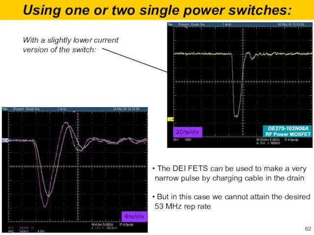
- 61. Using one or two single power switches: from DEI/IXYS RF min width pulses @20MHz: 20ns/div 1ms/div
- 62. Using one or two single power switches: The DEI FETS can be used to make a
- 64. Скачать презентацию
Слайд 3Unique Aspects/Challenges
Solenoidal focusing ⇒ cleaner, axisymmetric beam
Use of SC spoke
Unique Aspects/Challenges
Solenoidal focusing ⇒ cleaner, axisymmetric beam
Use of SC spoke
Слайд 4Robyn Madrak - FNAL APT Seminar - 12/16/2008
Parameters
* full un-chopped 3 msec
Robyn Madrak - FNAL APT Seminar - 12/16/2008
Parameters
* full un-chopped 3 msec
Слайд 5FNAL HINS
Robyn Madrak - FNAL APT Seminar - 12/16/2008
FNAL HINS
Robyn Madrak - FNAL APT Seminar - 12/16/2008
Слайд 6HINS Chopper – Part I
Should the HINS be extended to an
HINS Chopper – Part I
Should the HINS be extended to an
Слайд 7Traveling Wave Chopper Structure
beam is deflected by traveling pulse (electric field)
Traveling Wave Chopper Structure
beam is deflected by traveling pulse (electric field)
Слайд 8Chopper in MEBT
length of chopper plates: 50 cm
drift space downstream: 30 cm
Robyn
Chopper in MEBT
length of chopper plates: 50 cm
drift space downstream: 30 cm
Robyn
Слайд 9Deflection
length of chopper plates: 50 cm
drift space downstream: 30 cm
plate separation: 16
Deflection
length of chopper plates: 50 cm
drift space downstream: 30 cm
plate separation: 16
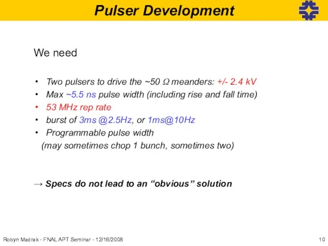
Слайд 10Pulser Development
Robyn Madrak - FNAL APT Seminar - 12/16/2008
We need
Two pulsers to
Pulser Development
Robyn Madrak - FNAL APT Seminar - 12/16/2008
We need
Two pulsers to
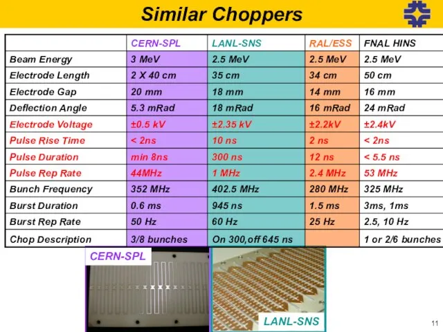
Слайд 11Similar Choppers
CERN-SPL
LANL-SNS
Similar Choppers
CERN-SPL
LANL-SNS
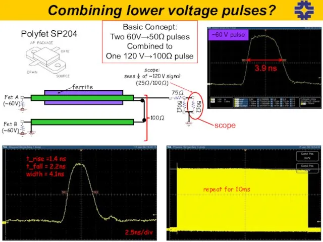
Слайд 12Combining lower voltage pulses?
scope:
sees ¼ of ~120V signal
(25Ω/100Ω)
Fet A
(~60V)
Fet B
(~60V)
75Ω
50Ω
100Ω
ferrite
50Ω
t_rise =1.4 ns
t_fall
Combining lower voltage pulses?
scope:
sees ¼ of ~120V signal
(25Ω/100Ω)
Fet A
(~60V)
Fet B
(~60V)
75Ω
50Ω
100Ω
ferrite
50Ω
t_rise =1.4 ns
t_fall
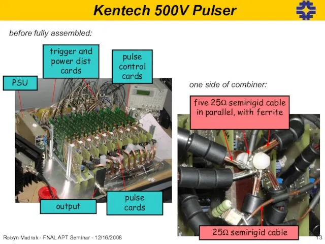
Слайд 13 Kentech 500V Pulser
pulse
control cards
PSU
pulse
cards
trigger and power dist cards
output
before fully assembled:
one side
Kentech 500V Pulser
pulse
control cards
PSU
pulse
cards
trigger and power dist cards
output
before fully assembled:
one side
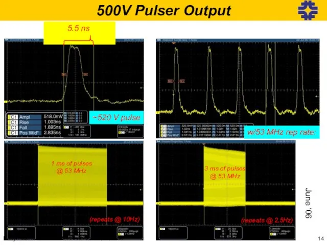
Слайд 14~520 V pulse
5.5 ns
1 ms of pulses
@ 53 MHz
3 ms of
~520 V pulse
5.5 ns
1 ms of pulses
@ 53 MHz
3 ms of
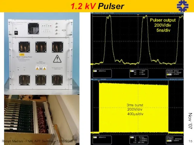
Слайд 15Pulser output
200V/div
5ns/div
3ms burst
200V/div
400μs/div
1.2 kV Pulser
Nov ‘07
Robyn Madrak - FNAL APT
Pulser output
200V/div
5ns/div
3ms burst
200V/div
400μs/div
1.2 kV Pulser
Nov ‘07
Robyn Madrak - FNAL APT
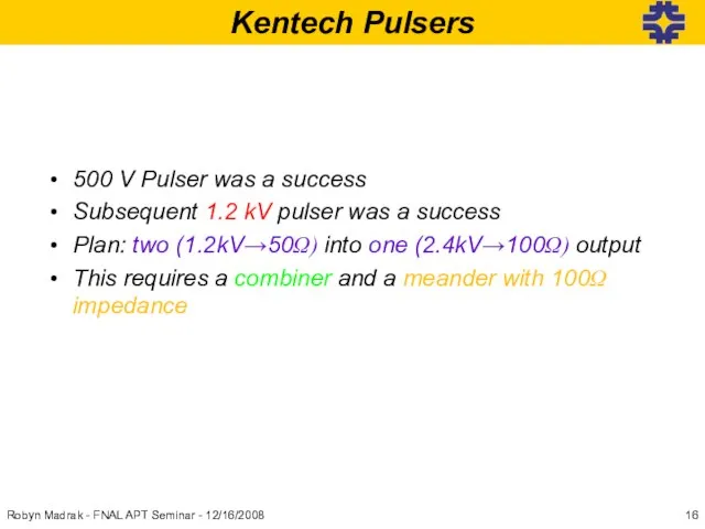
Слайд 16Kentech Pulsers
500 V Pulser was a success
Subsequent 1.2 kV pulser was a
Kentech Pulsers
500 V Pulser was a success
Subsequent 1.2 kV pulser was a
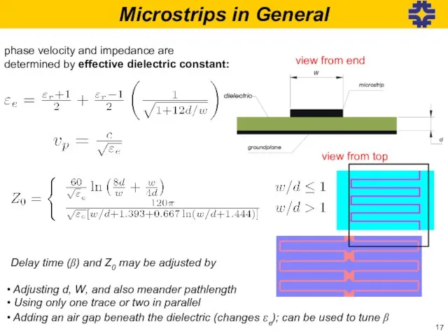
Слайд 17Microstrips in General
phase velocity and impedance are
determined by effective dielectric constant:
Delay time
Microstrips in General
phase velocity and impedance are
determined by effective dielectric constant:
Delay time
Слайд 18FNAL Fabricated Meanders
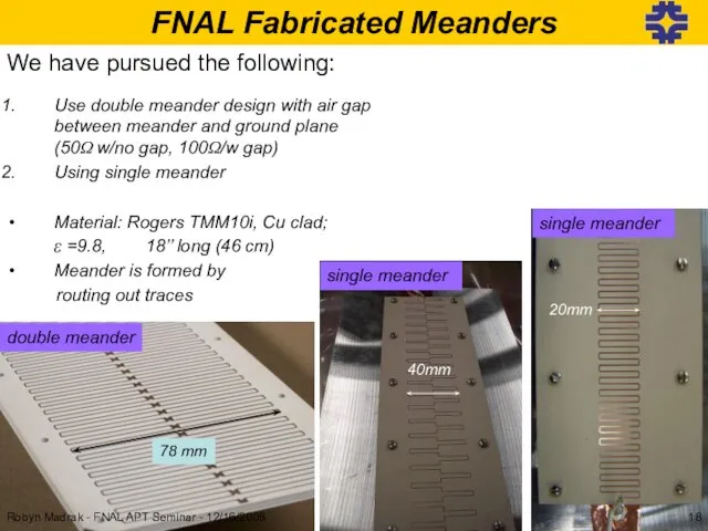
We have pursued the following:
Use double meander design with air
FNAL Fabricated Meanders
We have pursued the following:
Use double meander design with air
Слайд 19Chopper Meanders
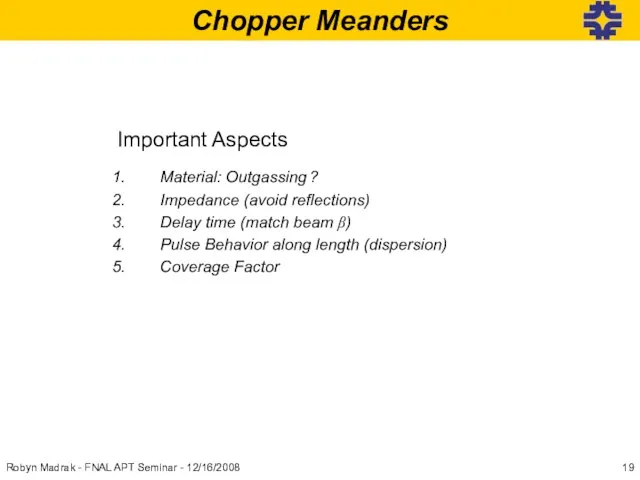
Important Aspects
Material: Outgassing ?
Impedance (avoid reflections)
Delay time (match beam β)
Pulse Behavior along
Chopper Meanders
Important Aspects
Material: Outgassing ?
Impedance (avoid reflections)
Delay time (match beam β)
Pulse Behavior along
Слайд 20Meander Substrate
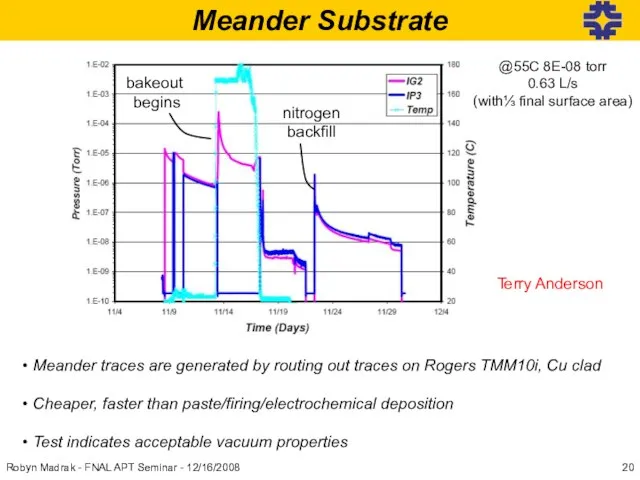
Meander traces are generated by routing out traces on Rogers
Meander Substrate
Meander traces are generated by routing out traces on Rogers
Слайд 21Double Meander, Impedance
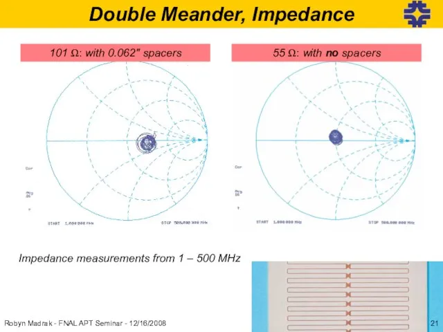
Impedance measurements from 1 – 500 MHz
Robyn Madrak - FNAL
Double Meander, Impedance
Impedance measurements from 1 – 500 MHz
Robyn Madrak - FNAL
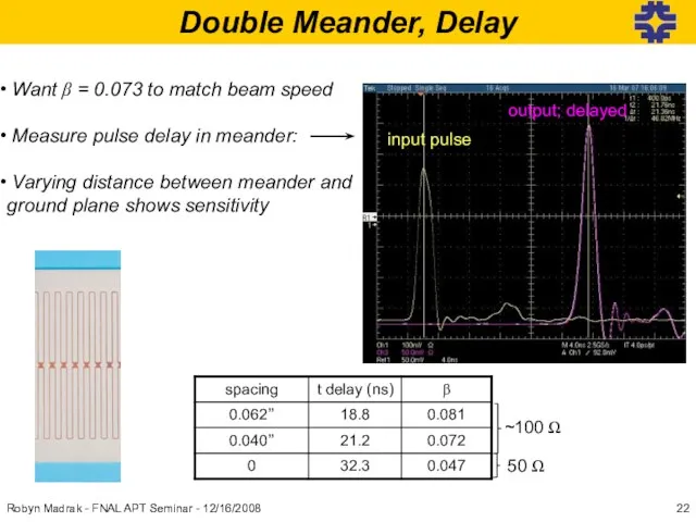
Слайд 22Double Meander, Delay
Robyn Madrak - FNAL APT Seminar - 12/16/2008
Want β
Double Meander, Delay
Robyn Madrak - FNAL APT Seminar - 12/16/2008
Want β
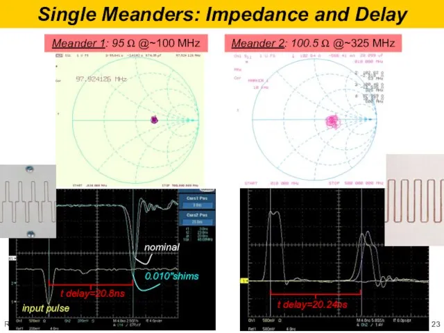
Слайд 23Single Meanders: Impedance and Delay
Meander 1: 95 Ω @~100 MHz
Meander 2: 100.5
Single Meanders: Impedance and Delay
Meander 1: 95 Ω @~100 MHz
Meander 2: 100.5
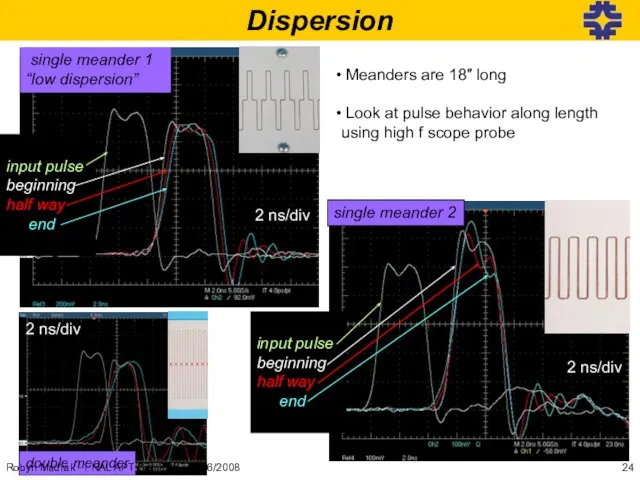
Слайд 24Dispersion
input pulse
beginning
half way
end
single meander 2
single meander 1
“low dispersion”
input pulse
Dispersion
input pulse
beginning
half way
end
single meander 2
single meander 1
“low dispersion”
input pulse
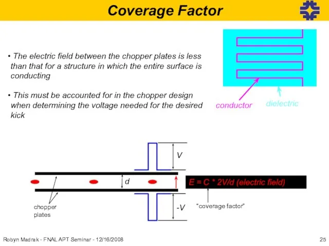
Слайд 25Coverage Factor
The electric field between the chopper plates is less than
Coverage Factor
The electric field between the chopper plates is less than
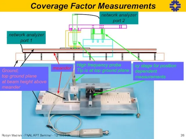
Слайд 26Coverage Factor Measurements
High frequency probe
Tip is at top ground plane
xy stage for
Coverage Factor Measurements
High frequency probe
Tip is at top ground plane
xy stage for
Слайд 27input pulse
@ end
@end
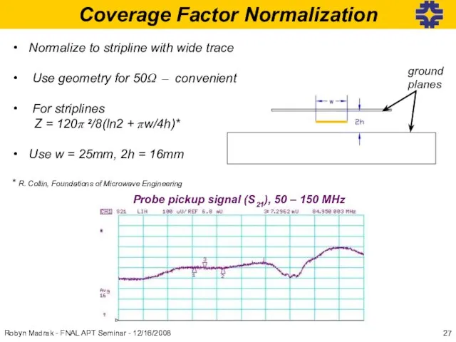
Coverage Factor Normalization
Normalize to stripline with wide trace
Use
input pulse
@ end
@end
Coverage Factor Normalization
Normalize to stripline with wide trace
Use
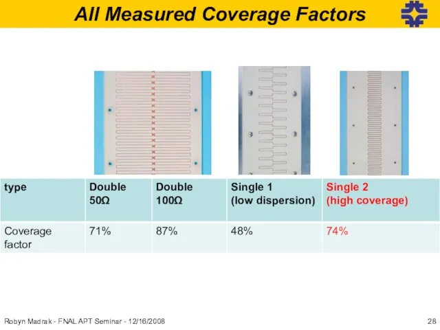
Слайд 28All Measured Coverage Factors
Robyn Madrak - FNAL APT Seminar - 12/16/2008
All Measured Coverage Factors
Robyn Madrak - FNAL APT Seminar - 12/16/2008
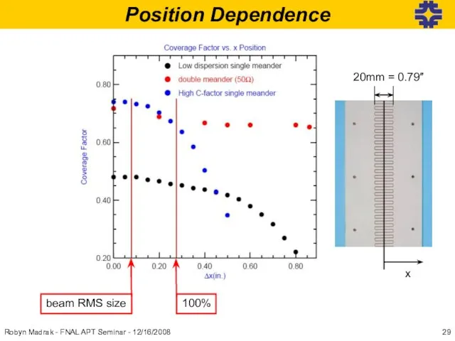
Слайд 29Position Dependence
beam RMS size
100%
x
Robyn Madrak - FNAL APT Seminar - 12/16/2008
20mm =
Position Dependence
beam RMS size
100%
x
Robyn Madrak - FNAL APT Seminar - 12/16/2008
20mm =
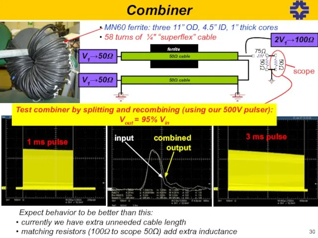
Слайд 303 ms pulse
combined output
input
50Ω cable
V1→50Ω
V1→50Ω
50Ω cable
MN60 ferrite: three 11’’ OD, 4.5’’
3 ms pulse
combined output
input
50Ω cable
V1→50Ω
V1→50Ω
50Ω cable
MN60 ferrite: three 11’’ OD, 4.5’’
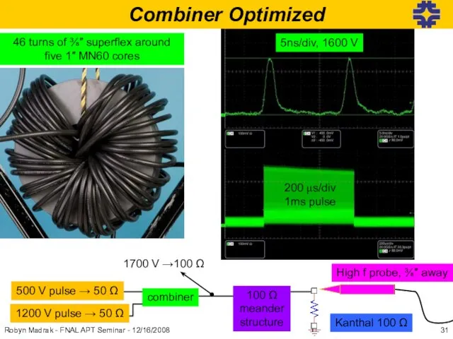
Слайд 31input
ferrite
46 turns of ⅜″ superflex around five 1″ MN60 cores
1700 V →100
input
ferrite
46 turns of ⅜″ superflex around five 1″ MN60 cores
1700 V →100
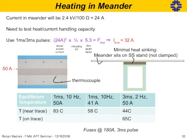
Слайд 32Heating in Meander
Current in meander will be 2.4 kV/100 Ω = 24
Heating in Meander
Current in meander will be 2.4 kV/100 Ω = 24
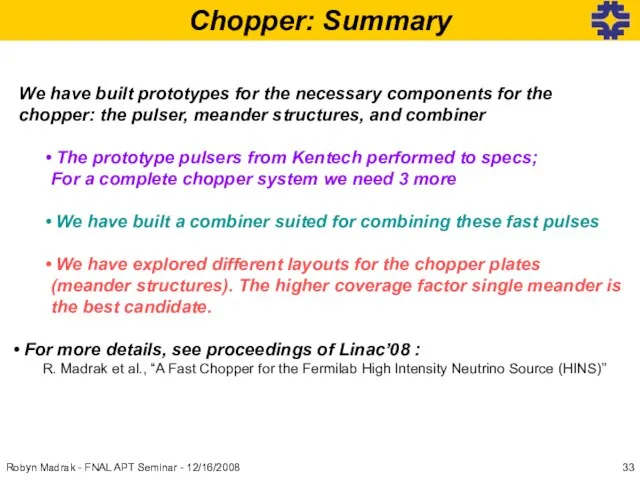
Слайд 33Chopper: Summary
We have built prototypes for the necessary components for the chopper:
Chopper: Summary
We have built prototypes for the necessary components for the chopper:
Слайд 34Aside: Application of Chopper R&D
to the current accelerator
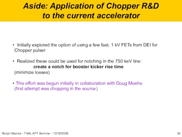
Initially explored the option
Aside: Application of Chopper R&D
to the current accelerator
Initially explored the option
Слайд 35Combining three DEI FETs
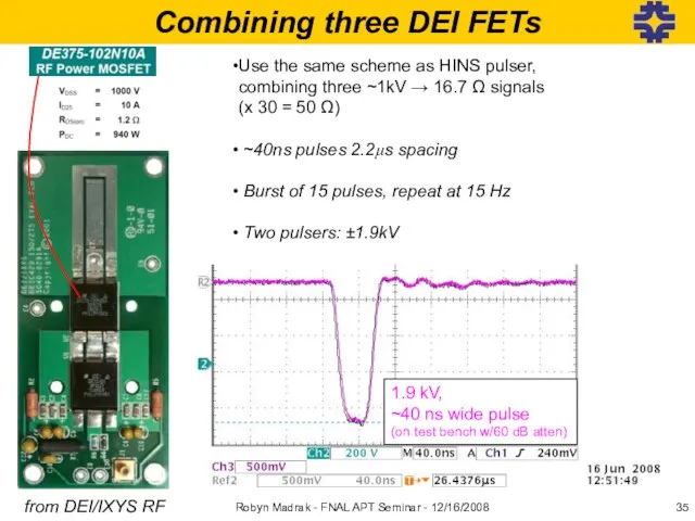
from DEI/IXYS RF
Use the same scheme as HINS pulser,
Combining three DEI FETs
from DEI/IXYS RF
Use the same scheme as HINS pulser,
Слайд 36Plates: 0.9″
spacing
W1
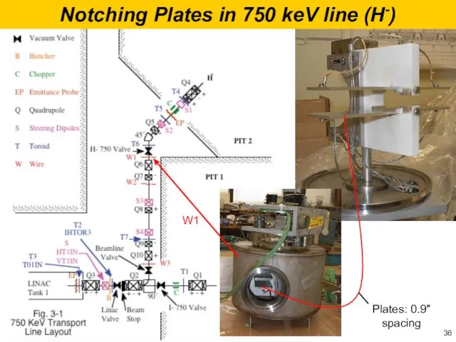
Notching Plates in 750 keV line (H-)
Plates: 0.9″
spacing
W1
Notching Plates in 750 keV line (H-)
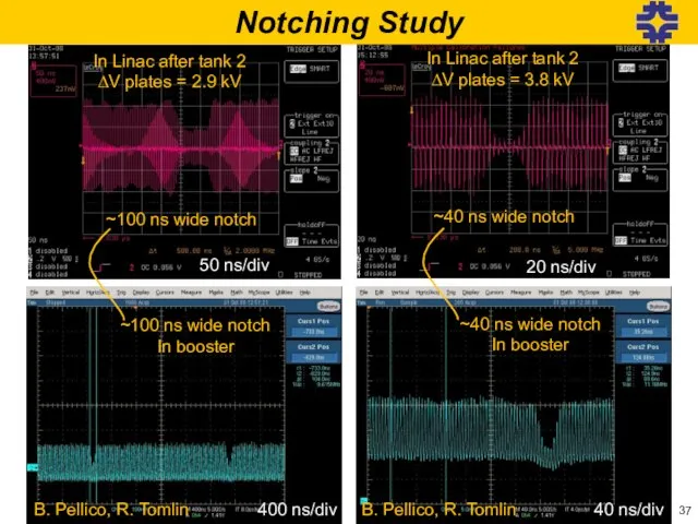
Слайд 37In Linac after tank 2
ΔV plates = 2.9 kV
~100 ns wide notch
50
In Linac after tank 2
ΔV plates = 2.9 kV
~100 ns wide notch
50
Слайд 38Robyn Madrak - FNAL APT Seminar - 12/16/2008
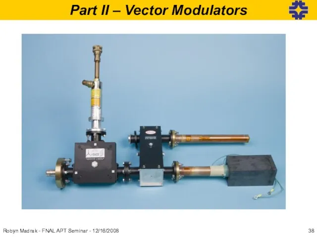
Part II – Vector Modulators
Robyn Madrak - FNAL APT Seminar - 12/16/2008
Part II – Vector Modulators
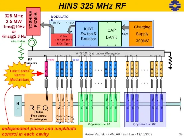
Слайд 39HINS 325 MHz RF
Pulse Transformer& Oil Tank
IGBT Switch & Bouncer
CAP
BANK
10 kV
110 kV
Charging
Supply
300kW
MODULATOR
325
HINS 325 MHz RF
Pulse Transformer& Oil Tank
IGBT Switch & Bouncer
CAP
BANK
10 kV
110 kV
Charging
Supply
300kW
MODULATOR
325
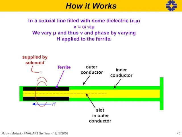
Слайд 40How it Works
In a coaxial line filled with some dielectric (ε,μ)
v =
How it Works
In a coaxial line filled with some dielectric (ε,μ)
v =
Слайд 41Robyn Madrak - FNAL APT Seminar - 12/16/2008
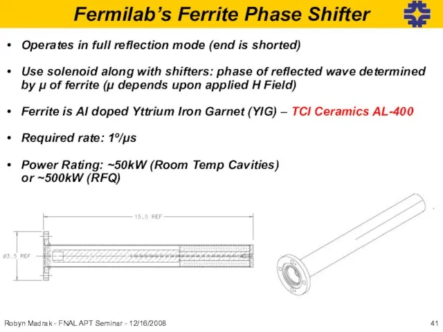
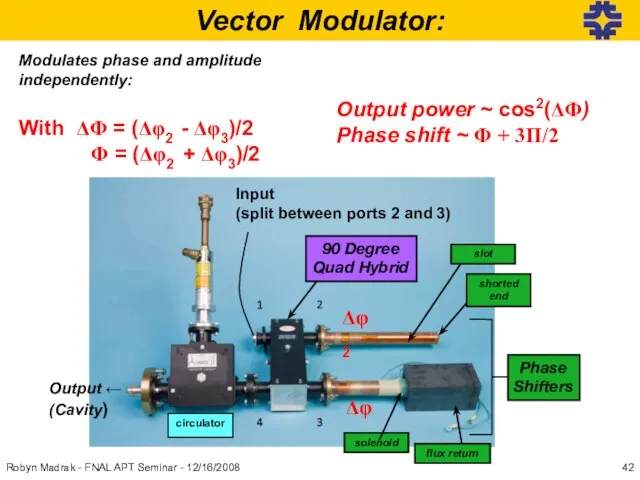
Operates in full reflection mode
Robyn Madrak - FNAL APT Seminar - 12/16/2008
Operates in full reflection mode
Слайд 42Modulates phase and amplitude independently:
With ΔΦ = (Δφ2 - Δφ3)/2
Φ =
Modulates phase and amplitude independently:
With ΔΦ = (Δφ2 - Δφ3)/2
Φ =
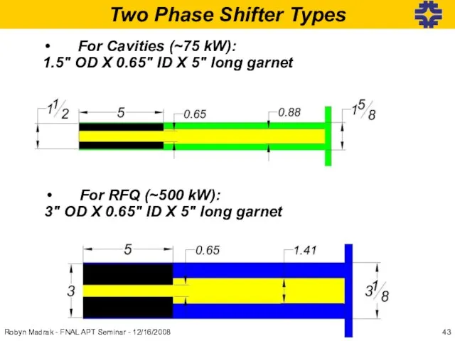
Слайд 43Two Phase Shifter Types
For Cavities (~75 kW):
1.5″ OD X 0.65″ ID X
Two Phase Shifter Types
For Cavities (~75 kW):
1.5″ OD X 0.65″ ID X
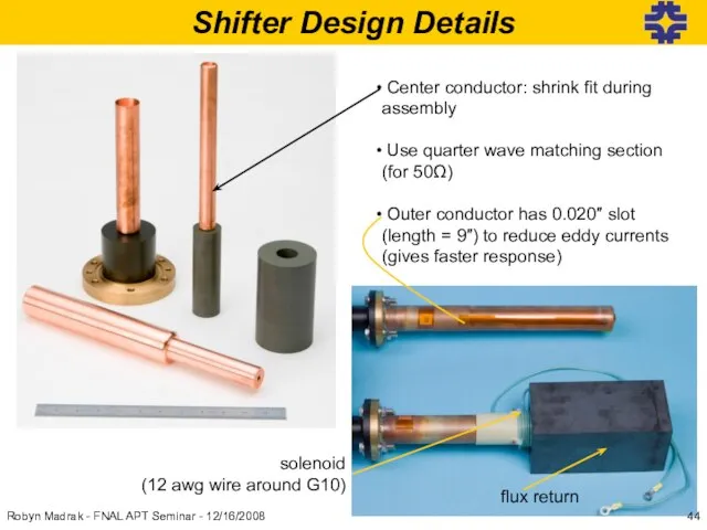
Слайд 44Shifter Design Details
Center conductor: shrink fit during assembly
Use quarter wave
Shifter Design Details
Center conductor: shrink fit during assembly
Use quarter wave
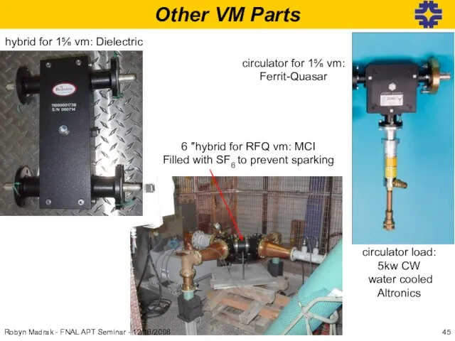
Слайд 45Other VM Parts
hybrid for 1⅝ vm: Dielectric
circulator for 1⅝ vm:
Ferrit-Quasar
circulator load:
5kw
Other VM Parts
hybrid for 1⅝ vm: Dielectric
circulator for 1⅝ vm:
Ferrit-Quasar
circulator load:
5kw
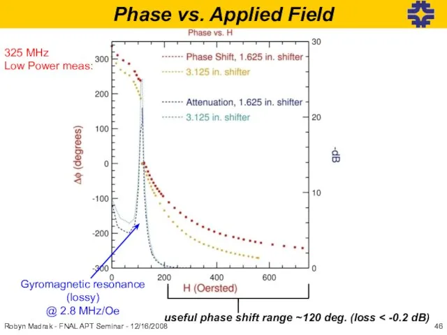
Слайд 46useful phase shift range ~120 deg. (loss < -0.2 dB)
Gyromagnetic resonance
(lossy)
@ 2.8
useful phase shift range ~120 deg. (loss < -0.2 dB)
Gyromagnetic resonance
(lossy)
@ 2.8
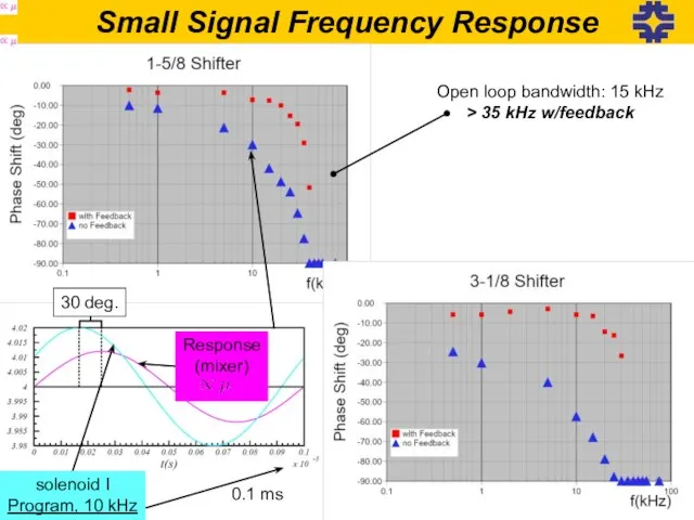
Слайд 47Small Signal Frequency Response
Open loop bandwidth: 15 kHz
> 35 kHz w/feedback
Response
(mixer)
solenoid
Small Signal Frequency Response
Open loop bandwidth: 15 kHz
> 35 kHz w/feedback
Response
(mixer)
solenoid
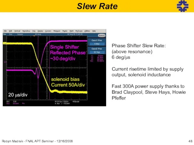
Слайд 48Slew Rate
Phase Shifter Slew Rate:
(above resonance)
6 deg/μs
Current risetime limited by supply output,
Slew Rate
Phase Shifter Slew Rate:
(above resonance)
6 deg/μs
Current risetime limited by supply output,
Слайд 49Robyn Madrak - FNAL APT Seminar - 12/16/2008
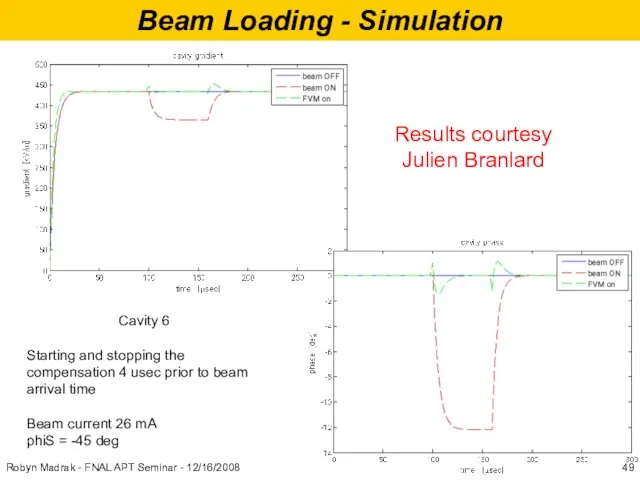
Beam Loading - Simulation
Cavity 6
Starting
Robyn Madrak - FNAL APT Seminar - 12/16/2008
Beam Loading - Simulation
Cavity 6
Starting
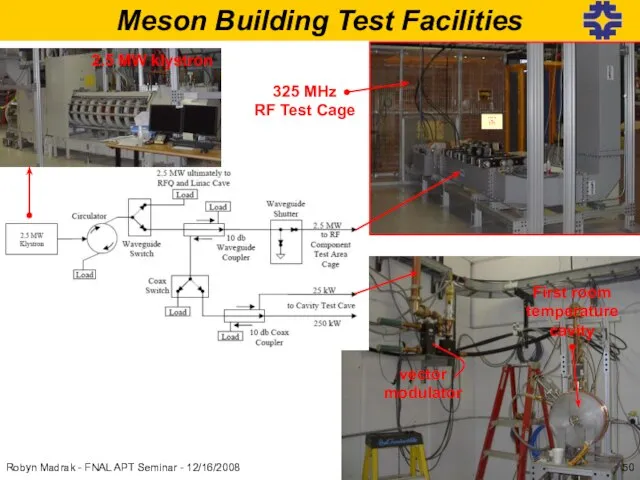
Слайд 50Meson Building Test Facilities
325 MHz
RF Test Cage
Please do not
feed the animals
2.5
Meson Building Test Facilities
325 MHz
RF Test Cage
Please do not
feed the animals
2.5
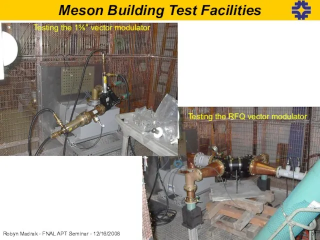
Слайд 51Meson Building Test Facilities
Testing the RFQ vector modulator
Testing the 1⅝″ vector modulator
Robyn
Meson Building Test Facilities
Testing the RFQ vector modulator
Testing the 1⅝″ vector modulator
Robyn
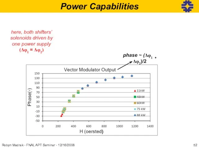
Слайд 52Power Capabilities
phase ~ (Δφ1 + Δφ2)/2
here, both shifters’ solenoids driven by one
Power Capabilities
phase ~ (Δφ1 + Δφ2)/2
here, both shifters’ solenoids driven by one
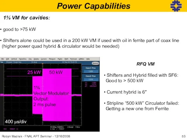
Слайд 53Power Capabilities
1⅝ VM for cavities:
good to >75 kW
Shifters
Power Capabilities
1⅝ VM for cavities:
good to >75 kW
Shifters
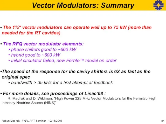
Слайд 54Vector Modulators: Summary
The 1⅝″ vector modulators can operate well up to
Vector Modulators: Summary
The 1⅝″ vector modulators can operate well up to
Слайд 55Robyn Madrak - FNAL APT Seminar - 12/16/2008
Conclusions
HINS is a key
Robyn Madrak - FNAL APT Seminar - 12/16/2008
Conclusions
HINS is a key
Слайд 56Backup Slides
Robyn Madrak - FNAL APT Seminar - 12/16/2008
Backup Slides
Robyn Madrak - FNAL APT Seminar - 12/16/2008
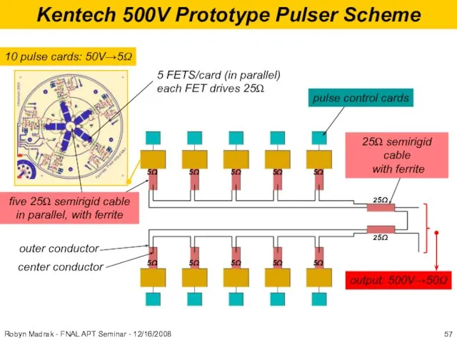
Слайд 57Kentech 500V Prototype Pulser Scheme
10 pulse cards: 50V→5Ω
5 FETS/card (in parallel)
each FET
Kentech 500V Prototype Pulser Scheme
10 pulse cards: 50V→5Ω
5 FETS/card (in parallel)
each FET
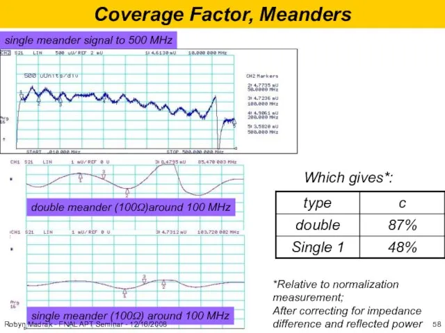
Слайд 58Coverage Factor, Meanders
single meander signal to 500 MHz
double meander (100Ω)around 100 MHz
single
Coverage Factor, Meanders
single meander signal to 500 MHz
double meander (100Ω)around 100 MHz
single
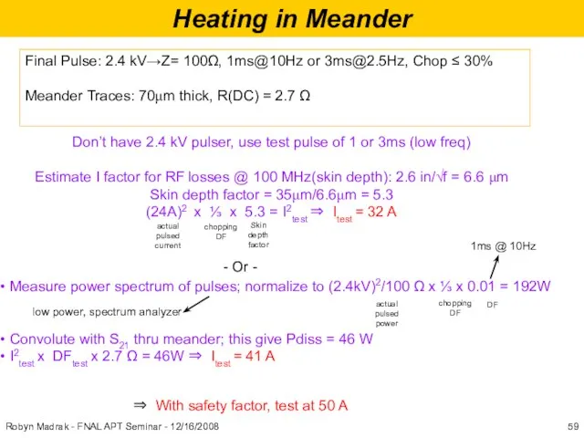
Слайд 59Heating in Meander
Final Pulse: 2.4 kV→Z= 100Ω, 1ms@10Hz or [email protected], Chop ≤
Heating in Meander
Final Pulse: 2.4 kV→Z= 100Ω, 1ms@10Hz or [email protected], Chop ≤
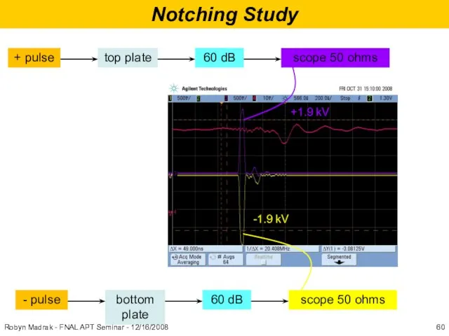
Слайд 60Notching Study
+1.9 kV
-1.9 kV
Robyn Madrak - FNAL APT Seminar - 12/16/2008
Notching Study
+1.9 kV
-1.9 kV
Robyn Madrak - FNAL APT Seminar - 12/16/2008
Слайд 61Using one or two single power switches:
from DEI/IXYS RF
min width pulses @20MHz:
20ns/div
1ms/div
→
Using one or two single power switches:
from DEI/IXYS RF
min width pulses @20MHz:
20ns/div
1ms/div
→
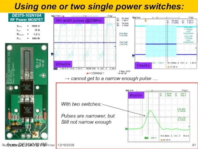
Слайд 62Using one or two single power switches:
The DEI FETS can be
Using one or two single power switches:
The DEI FETS can be
 Профессиональные конкурсы как средство повышения педагогической компетентности учителя
 Всего 140 б-ней. Около 70 основных. Болезни заднего прохода - у 70-80% обследуемых. Жалобы на органы пищеварения предъявляли 44% мужчин и 55%
  Адаптационный семинар по проектам Программы «Научный фонд НИУ ВШЭ»
 Яндекс.Маркет: на что стоит обратить внимание
 Интерактивные курсы обучения по гастроэнтерологии
 Площади плоских фигур
 Учимся выполнять тестовые задания ОГЭ - 2015
 Правила дорожного движения
 Внимание!!! «Компания Черлин» представляет принципиально новую линейку пены для ванн «Кураж» с морской солью!
 ...в нашем трансчеловеческом будущем
 Рабочая программа по предмету "Изобразительное искусство"
 Буддийский храм в Петербурге – уникальное сооружение в Европе Подготовила: учитель истории и культуры Санкт-Петербурга ГБОУ №471
 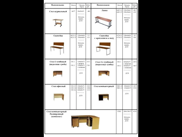 Стол журнальный
 Как увеличить доход при действующих расходах с помощью Boxberry
 Аттестационная работа. Мой мир - путь к успеху
 Северная война 1700 – 1721 г.г
 Дизайн-мышление и сервис-дизайн: как повернуть бизнес лицом к человеку
 Презентация на тему Дает силы нам всегда витаминная еда!
 Международная система защиты прав человека
 Презентация на тему Город Курск
 Chandler Belgium BVBA
 Защитники Отечества. Вооруженные Силы Российской Федерации
 Конструктивные особенности покрытий зданий
 О чем поведал натюрморт. ИЗО, 7 класс
 Шок в клинике внутренних болезней
 Обзор наукометрических показателей и баз данных
  О роли методического объединения в профессиональном развитии педагога
  Boost business. Bonusway company