- Walking Machine Technology

Содержание
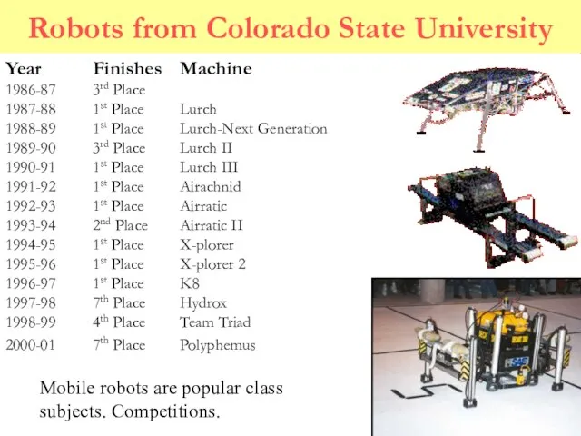
- 2. Robots from Colorado State University Year Finishes Machine 1986-87 3rd Place 1987-88 1st Place Lurch 1988-89
- 3. Design of a Rough Terrain Vehicle (RTV)
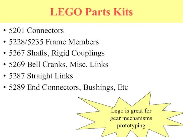
- 4. LEGO Parts Kits 5201 Connectors 5228/5235 Frame Members 5267 Shafts, Rigid Couplings 5269 Bell Cranks, Misc.
- 5. LEGO Parts Kits 9854 Rack & Pinion Gears 9965 Two sizes, small spur gears 9966 Two
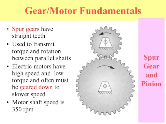
- 6. Gear/Motor Fundamentals Spur gears have straight teeth Used to transmit torque and rotation between parallel shafts
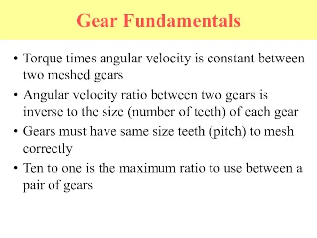
- 7. Gear Fundamentals Torque times angular velocity is constant between two meshed gears Angular velocity ratio between
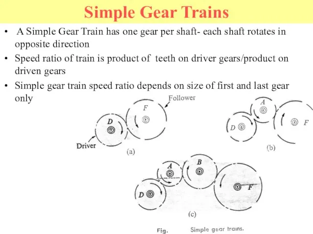
- 8. Simple Gear Trains A Simple Gear Train has one gear per shaft- each shaft rotates in
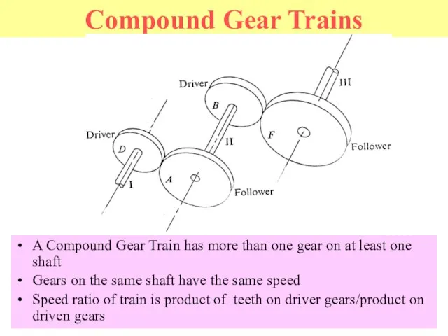
- 9. Compound Gear Trains A Compound Gear Train has more than one gear on at least one
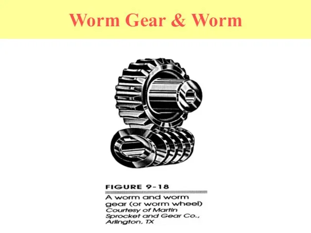
- 10. Worm Gear & Worm
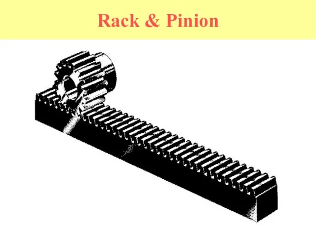
- 11. Rack & Pinion
- 12. Straight Bevel Gears
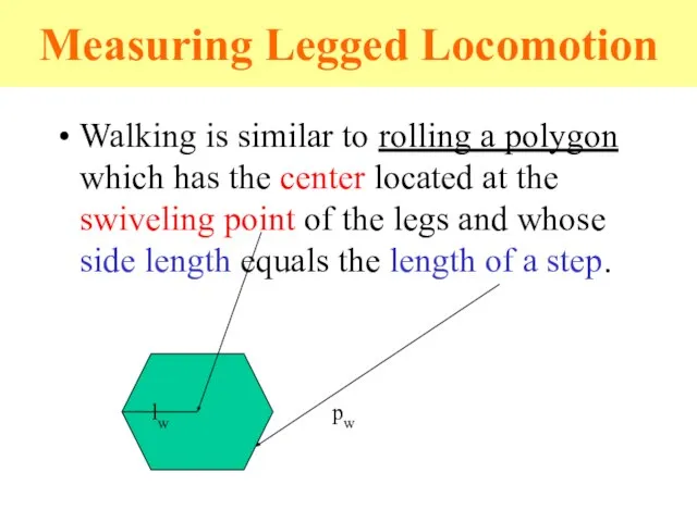
- 13. Measuring Legged Locomotion Walking is similar to rolling a polygon which has the center located at
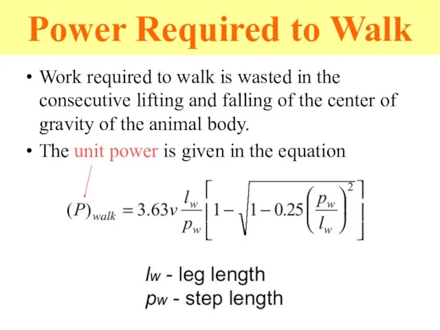
- 14. Power Required to Walk Work required to walk is wasted in the consecutive lifting and falling
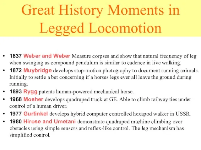
- 16. Great History Moments in Legged Locomotion 1837 Weber and Weber Measure corpses and show that natural
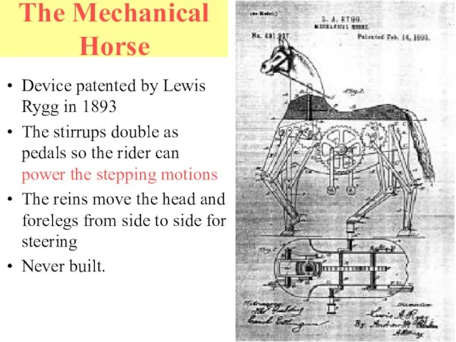
- 17. The Mechanical Horse Device patented by Lewis Rygg in 1893 The stirrups double as pedals so
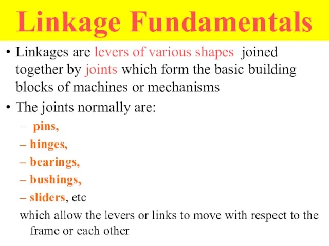
- 18. Linkage Fundamentals Linkages are levers of various shapes joined together by joints which form the basic
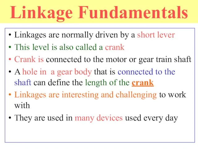
- 19. Linkage Fundamentals Linkages are normally driven by a short lever This level is also called a
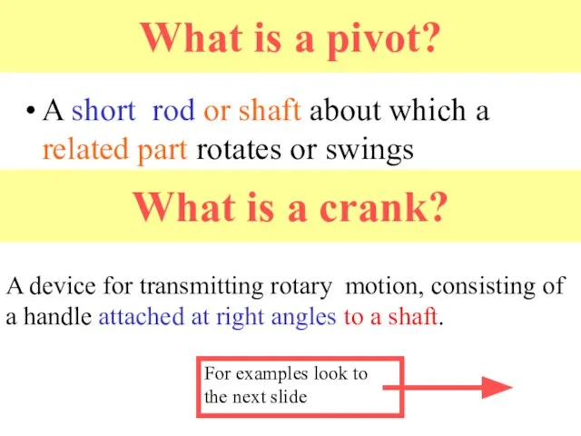
- 20. What is a pivot? A short rod or shaft about which a related part rotates or
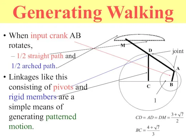
- 21. Generating Walking When input crank AB rotates, – 1/2 straight path and 1/2 arched path. Linkages
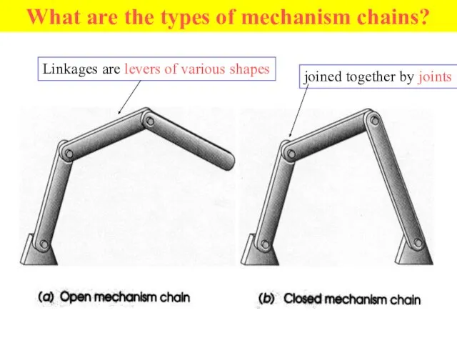
- 22. What are the types of mechanism chains? Linkages are levers of various shapes joined together by
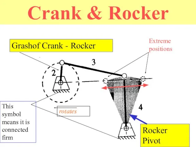
- 23. Crank & Rocker Rocker Pivot Grashof Crank - Rocker rotates Extreme positions This symbol means it
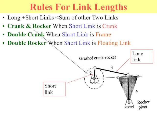
- 24. Rules For Link Lengths Long +Short Links Crank & Rocker When Short Link is Crank Double
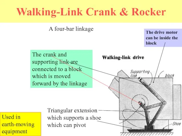
- 25. Walking-Link Crank & Rocker A four-bar linkage Triangular extension which supports a shoe which can pivot
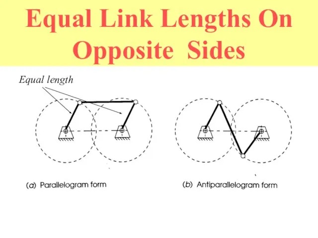
- 26. Equal Link Lengths On Opposite Sides Equal length
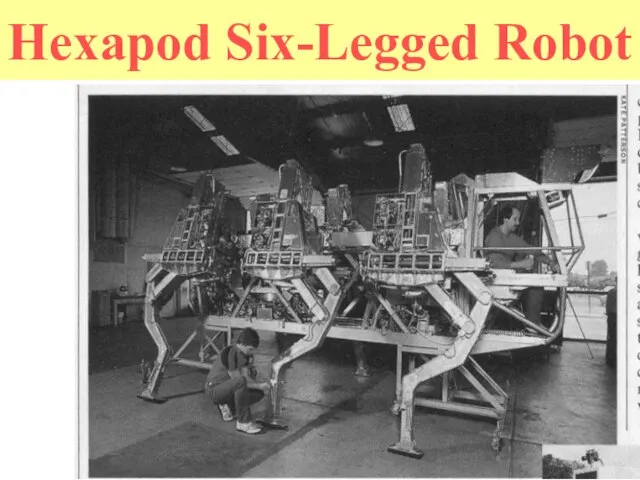
- 27. Hexapod Six-Legged Robot
- 28. Another Hexapod
- 29. Walking Plates
- 30. More Great History Moments 1983 Odetics demonstrates a self-contained hexapod which lifts and moves back end
- 31. Two Legged Vehicle--The P2 Honda Motor Co. Obstacle Avoidance by stepping over and around. can walk
- 32. Hexapods from Lynxmotion
- 33. Lynxmotion Kits Hexapods Cars Arms Quadrupeds Lynxmotion Hexapods
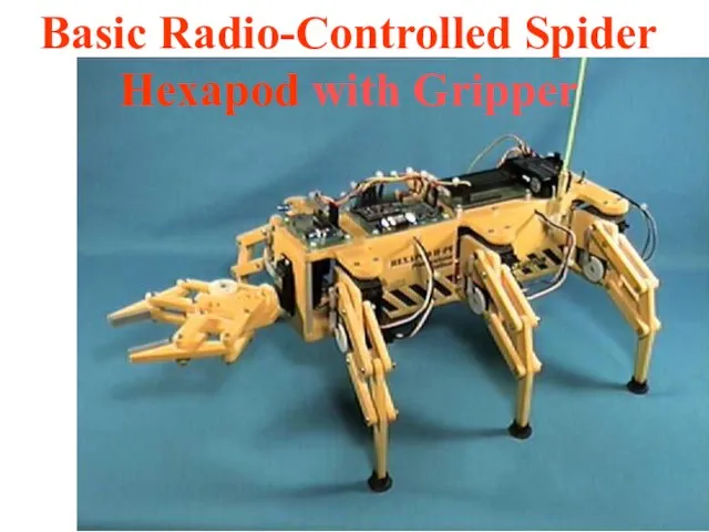
- 34. Basic Radio-Controlled Spider Hexapod with Gripper
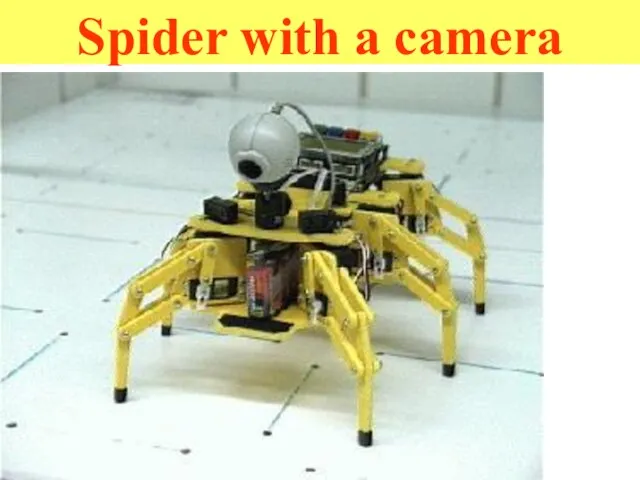
- 35. Spider with a camera
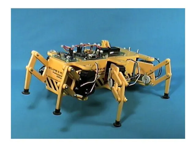
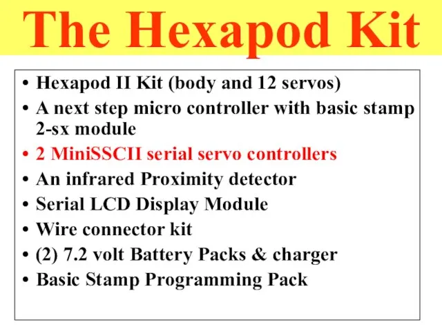
- 37. The Hexapod Kit Hexapod II Kit (body and 12 servos) A next step micro controller with
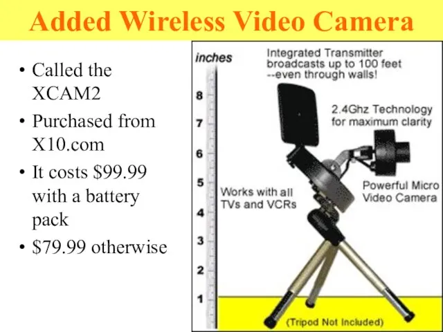
- 38. Added Wireless Video Camera Called the XCAM2 Purchased from X10.com It costs $99.99 with a battery
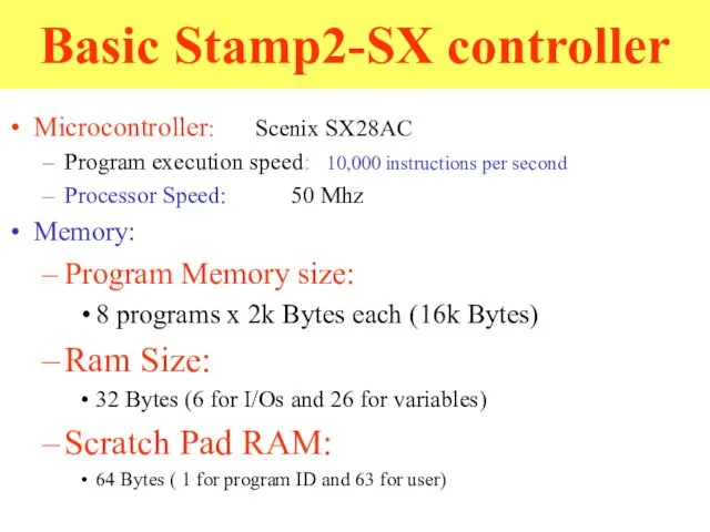
- 39. Basic Stamp2-SX controller Microcontroller: Scenix SX28AC Program execution speed: 10,000 instructions per second Processor Speed: 50
- 40. Controller continued… Inputs/Outputs: 16 + 2 dedicated serial I/O Current @ 5v: 60mA Run / 200
- 41. Next Step Carrier Board Basic stamp 2-sx module plugs into the Next Step Microcontroller Supplies: Serial
- 42. Component Interconnections The Next Step has the Basic Stamp 2 module on it Other components are
- 43. Serial LCD Display Power, ground and a single data connection Serial information is sent via the
- 44. IRPD IRPD = Infra Red Proximity Detector Connected to power and ground Three I/O ports: Left
- 45. Infra Red Proximity Detector
- 46. MiniSSCII servo controller Receives serial data: Which servo Move to what position Control 8 servos per
- 47. Hexapod II Configuration Two MiniSSCIIs working together Six servos per controller: one controller: 0 to 5
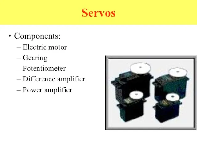
- 48. Servos Components: Electric motor Gearing Potentiometer Difference amplifier Power amplifier
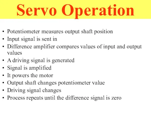
- 49. Servo Operation Potentiometer measures output shaft position Input signal is sent in Difference amplifier compares values
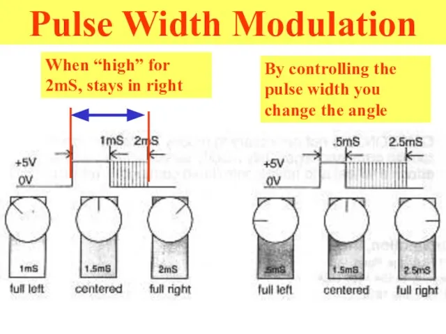
- 50. Pulse Width Modulation When “high” for 2mS, stays in right By controlling the pulse width you
- 51. Notable Features Variable speed Input signal is pulse width modulation Pulses ranging from 1 to 2
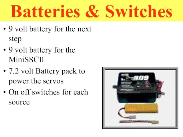
- 52. Batteries & Switches 9 volt battery for the next step 9 volt battery for the MiniSSCII
- 57. Programming PBasic programming language Syntax described in book Provided text editor Compiles on PC and downloads
- 58. What have we added? 2 Radio frequency transceivers Computer serial port Onboard robot I/O pin Video
- 59. Hexapod Kit Purchasing The Lynxmotion Hexapod II Professional Edition Combo kit Their company web page www.lynxmotion.com
- 60. Problems with Lynxmotion hexapods Weight Servos make the vehicle quite top heavy and may add to
- 61. RHex RHex Other Hexapods
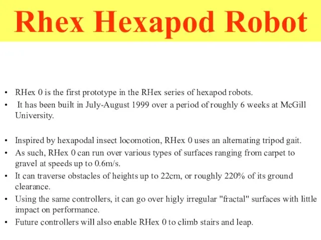
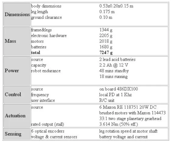
- 62. RHex 0 is the first prototype in the RHex series of hexapod robots. It has been
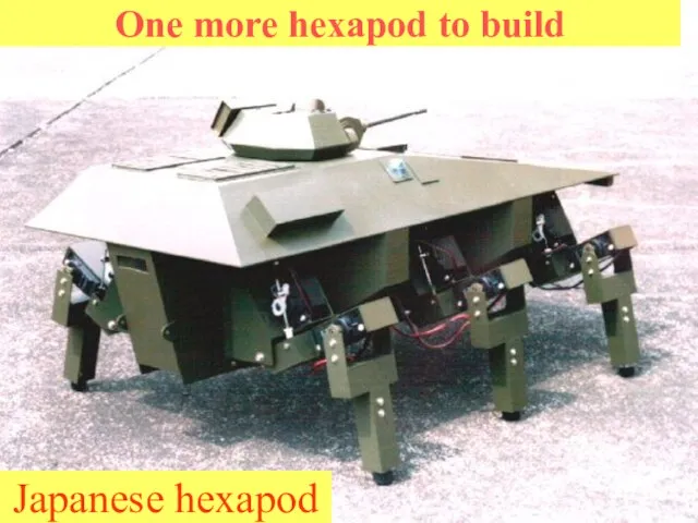
- 64. One more hexapod to build Japanese hexapod
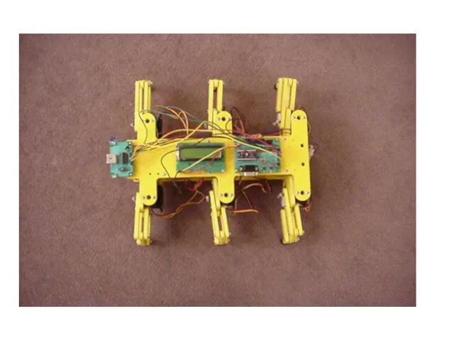
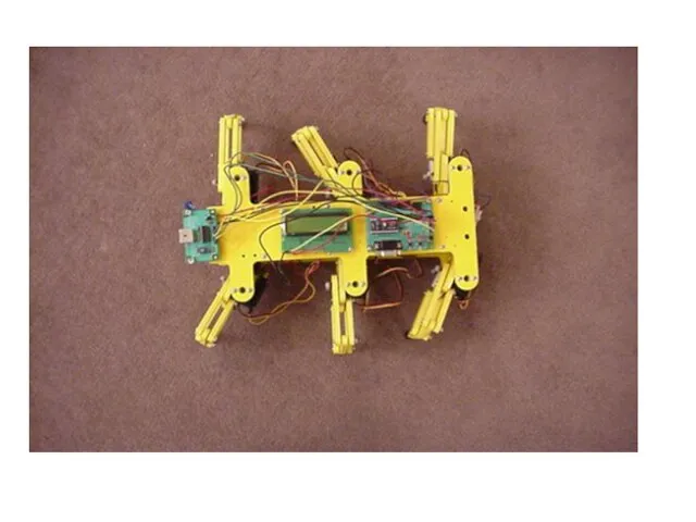
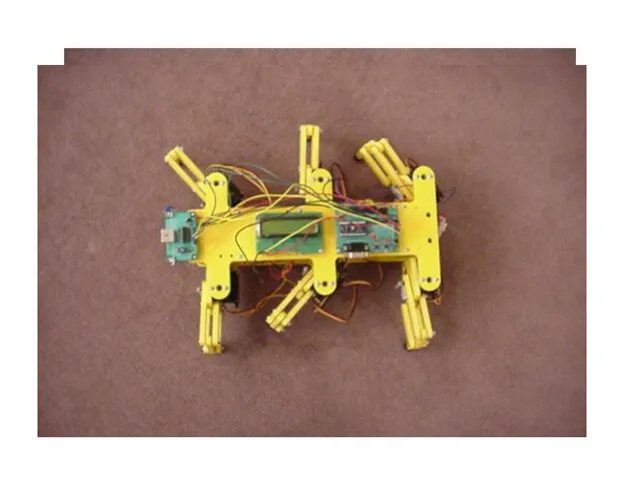
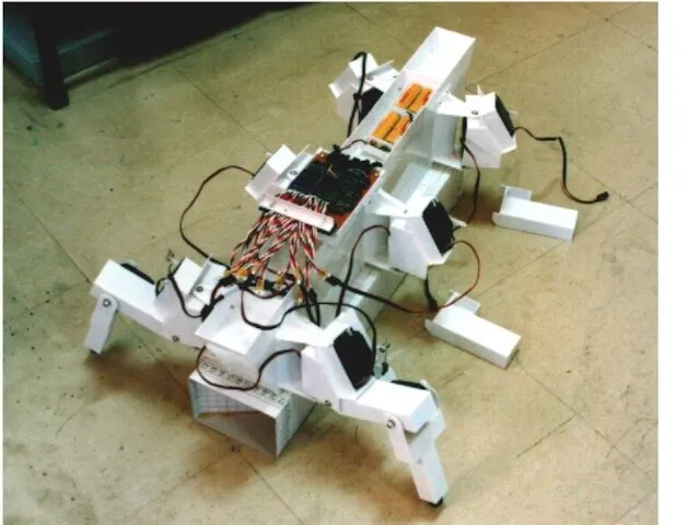
- 65. Introduction to Japanese hexapod This is a hexapod robot powered by 18 RC servomotors. The degree
- 66. Introduction to Japanese hexapod
- 67. Mechanical Structure and Arrangement The robot consists of 3 major parts: 1. "The Cover", 2. "The
- 68. Cover This is the part that looks like tank. It is made from plastic plate. The
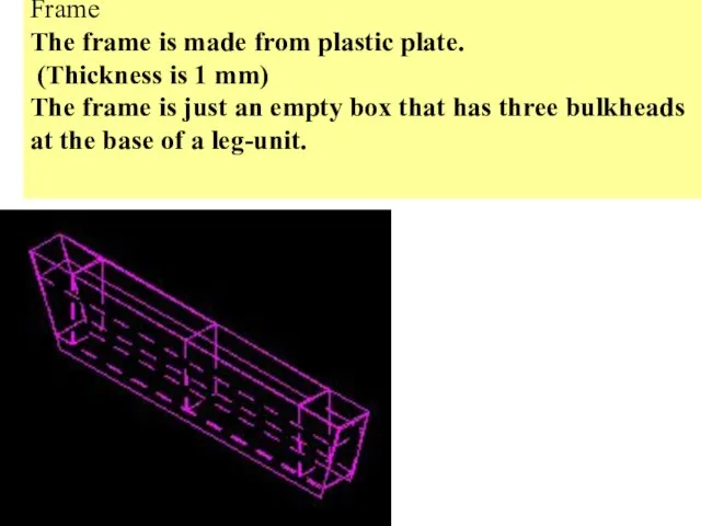
- 69. Frame The frame is made from plastic plate. (Thickness is 1 mm) The frame is just
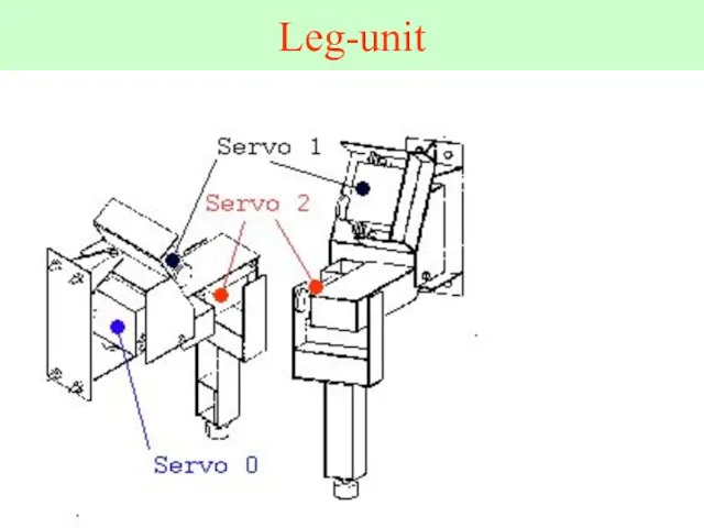
- 70. Leg-unit
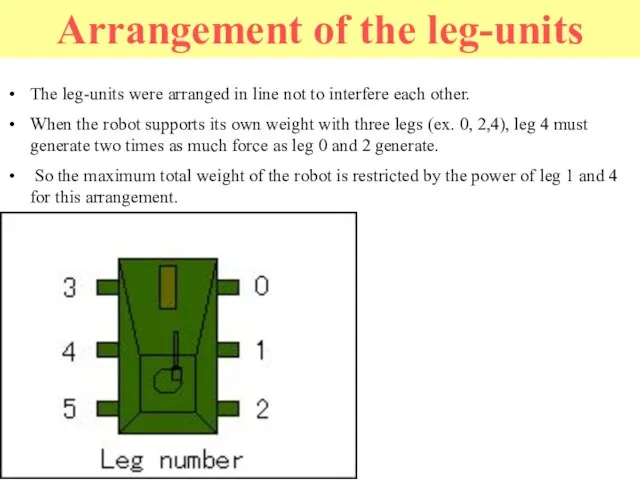
- 71. Layout of servomotors To increase inertia of parts to be actuated is not good from the
- 73. The leg-units were arranged in line not to interfere each other. When the robot supports its
- 74. All the axles that are opposite side of servomotors have a simple mechanism to reduce the
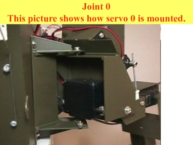
- 75. Joint 0 This picture shows how servo 0 is mounted.
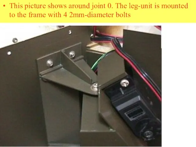
- 76. This picture shows around joint 0. The leg-unit is mounted to the frame with 4 2mm-diameter
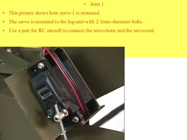
- 77. Joint 1 This picture shows how servo 1 is mounted. The servo is mounted to the
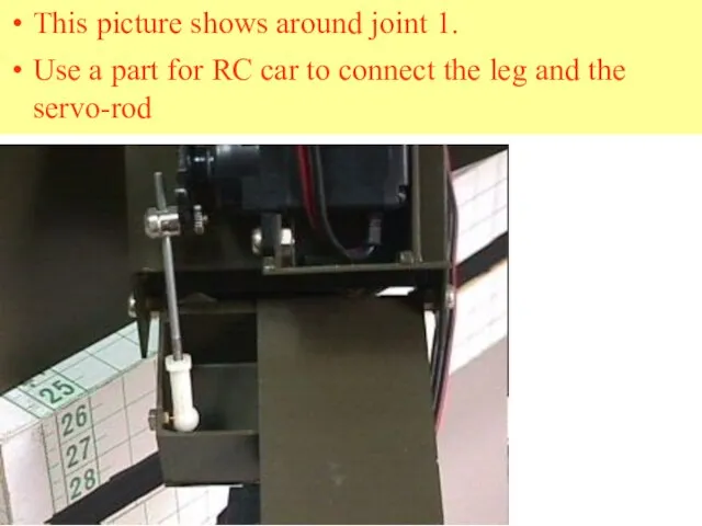
- 78. This picture shows around joint 1. Use a part for RC car to connect the leg
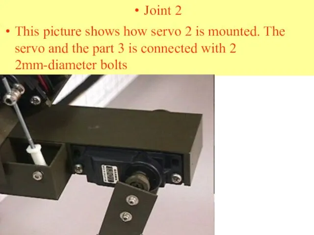
- 79. Joint 2 This picture shows how servo 2 is mounted. The servo and the part 3
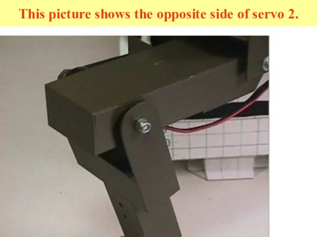
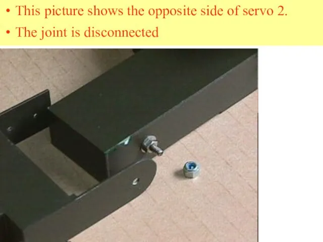
- 80. This picture shows the opposite side of servo 2.
- 81. This picture shows the opposite side of servo 2. The joint is disconnected
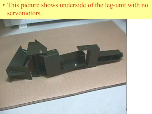
- 82. This picture shows underside of the leg-unit with no servomotors.
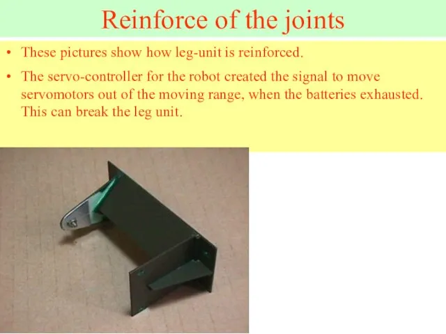
- 83. Reinforce of the joints These pictures show how leg-unit is reinforced. The servo-controller for the robot
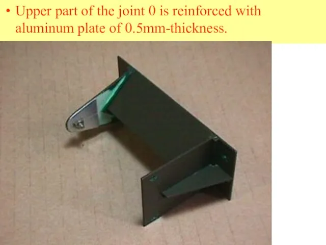
- 84. Upper part of the joint 0 is reinforced with aluminum plate of 0.5mm-thickness.
- 85. The joint 1 is reinforced with plastic plate of 1.0mm-thickness. The base of the servo-rod is
- 86. Project Description Autonomous eight-legged robot specially designed to complete a ten meters track of unknown configuration.
- 87. Key Features Is autonomous Is compact Has special retro-reflective sensors for tracking purposes Has micro-controller and
- 88. Technical Specifications Rechargeable power source 12 volt dc supply Infrared remote wireless control Range of up
- 89. Multi-legged Mobile Robot Design of the Control System Adaptation of Mekatronix Hexapod
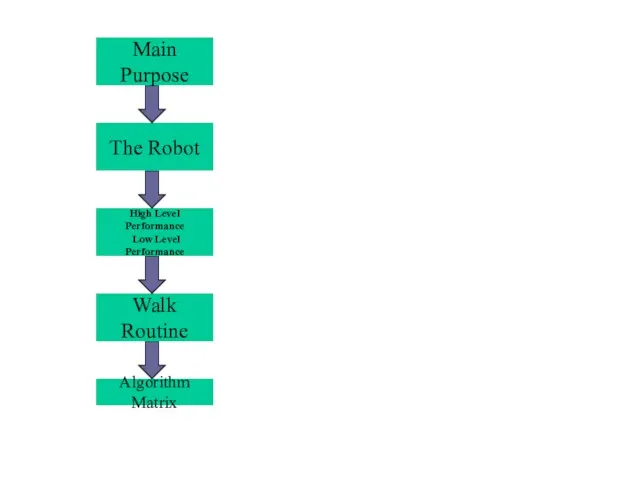
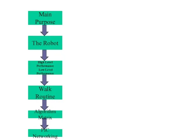
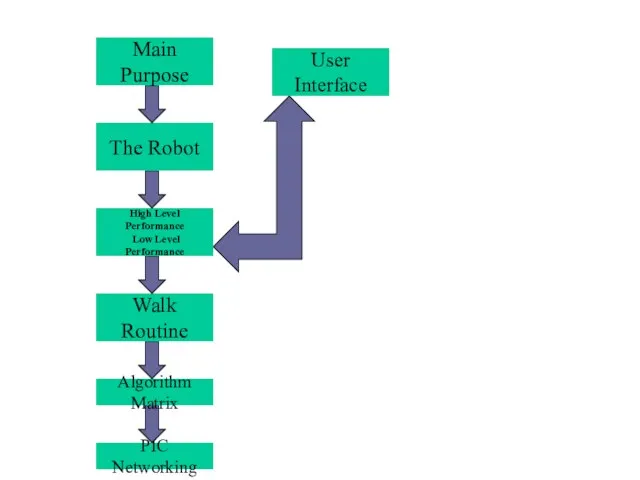
- 90. Main Purpose
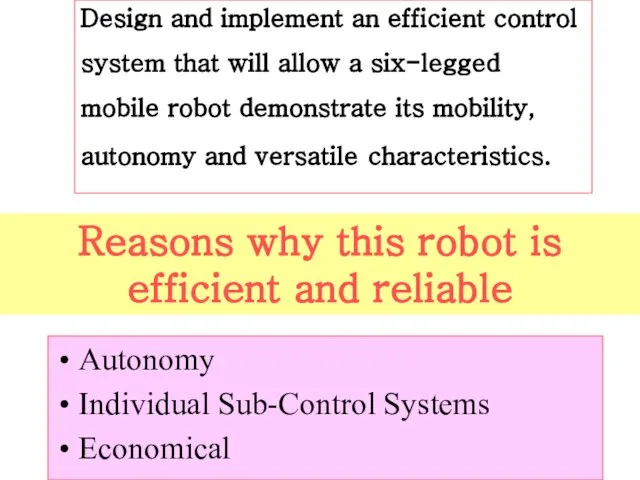
- 91. Design and implement an efficient control system that will allow a six-legged mobile robot demonstrate its
- 92. The Robot Main Purpose
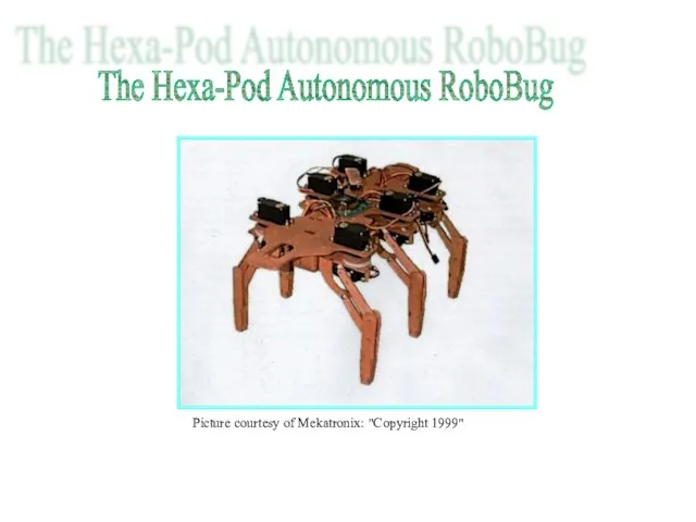
- 93. The Hexa-Pod Autonomous RoboBug Picture courtesy of Mekatronix: "Copyright 1999"
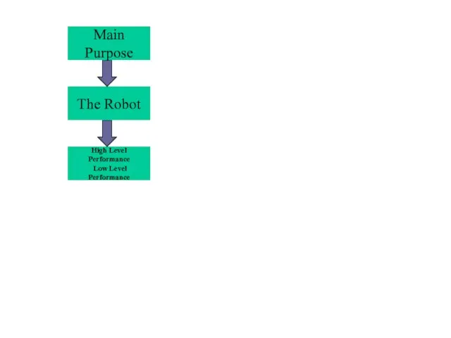
- 94. High Level Performance Low Level Performance The Robot Main Purpose
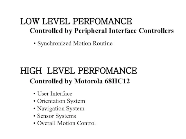
- 95. LOW LEVEL PERFOMANCE Controlled by Peripheral Interface Controllers HIGH LEVEL PERFOMANCE Controlled by Motorola 68HC12 Synchronized
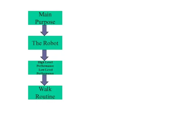
- 96. Walk Routine
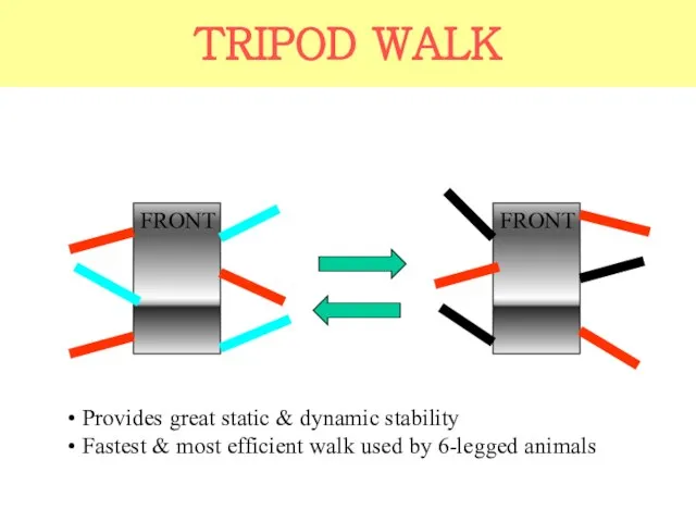
- 97. TRIPOD WALK FRONT FRONT Provides great static & dynamic stability Fastest & most efficient walk used
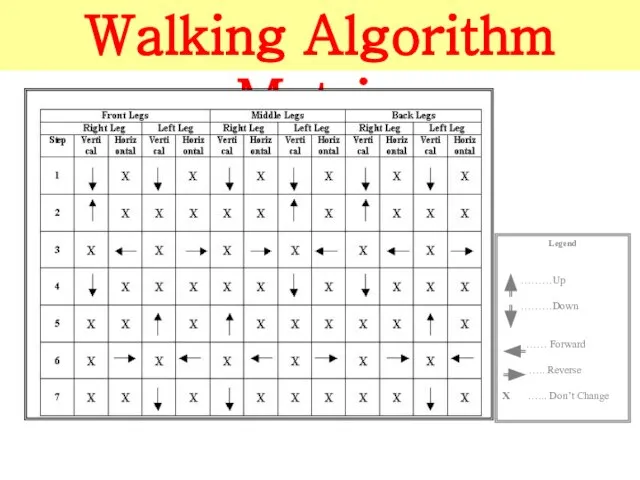
- 98. Algorithm Matrix
- 99. Walking Algorithm Matrix
- 100. PIC Networking
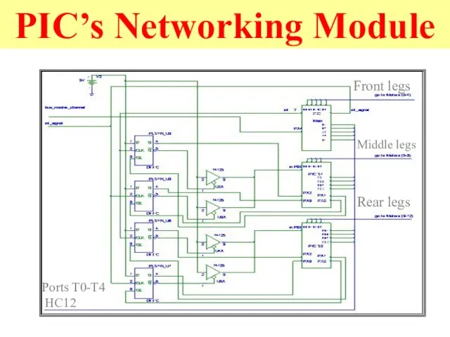
- 101. PIC’s Networking Module Front legs Middle legs Rear legs Ports T0-T4 HC12
- 102. User Interface
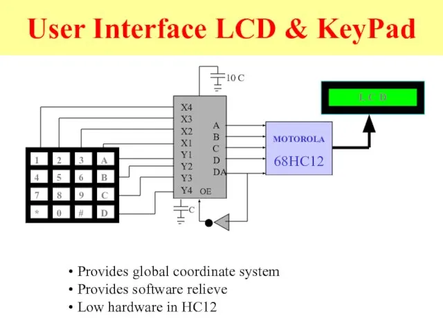
- 103. User Interface LCD & KeyPad MOTOROLA 68HC12 Provides global coordinate system Provides software relieve Low hardware
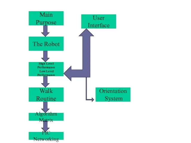
- 104. Orientation System User Interface
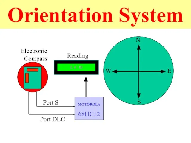
- 105. Orientation System Electronic Compass Reading
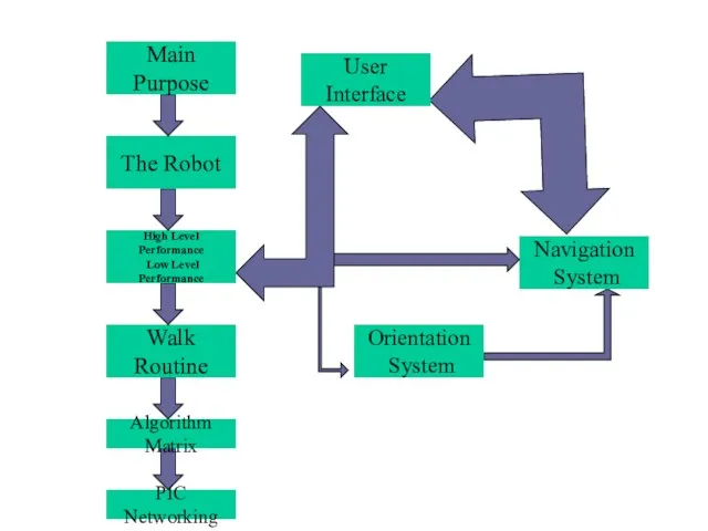
- 106. Navigation System Orientation System User Interface
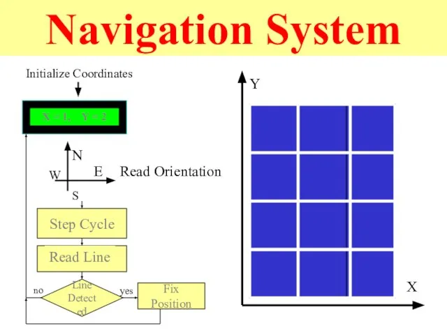
- 107. Navigation System X Y Initialize Coordinates N S E W Read Orientation Step Cycle Line Detected
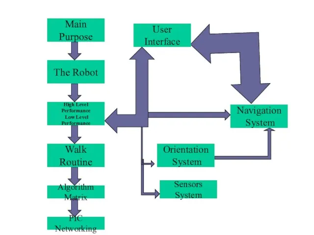
- 108. Navigation System Sensors System User Interface
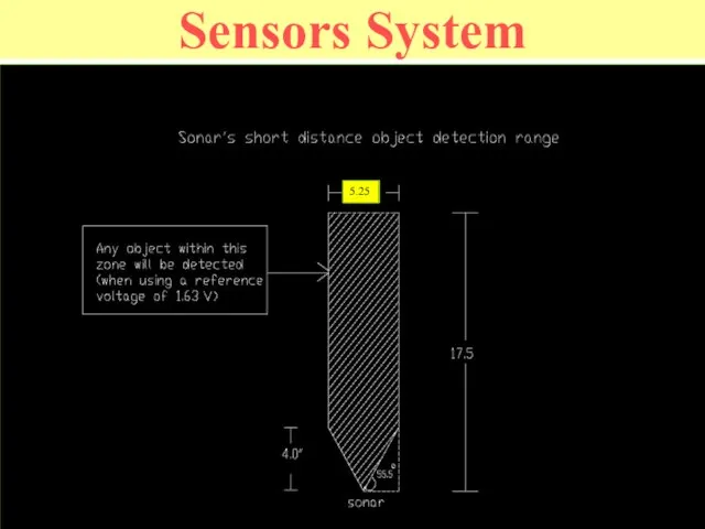
- 109. Sensors System
- 110. Overall System Diagram SONAR & IR SENSORS MOTOROLA 68HC12 1 2 C 3 6 9 B
- 111. WMC Competition Overview
- 112. Polyphemus - Competition Complete all events: Dash, Load Retrieval, Slalom, Trip Wire, Object Retrieval, Obstacle Course,
- 113. 8-Legged Polyphemus Articulated “Legs” On-board Power Self-Contained (tethered) Analogy in Nature
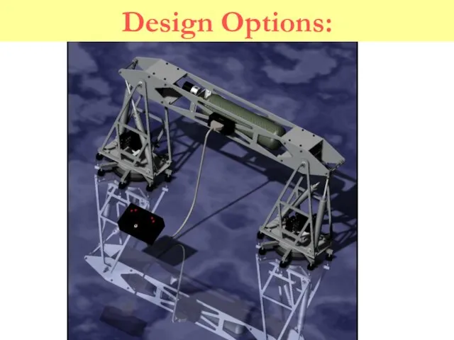
- 114. Design Options:
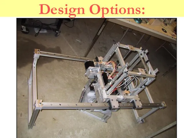
- 115. Design Options:
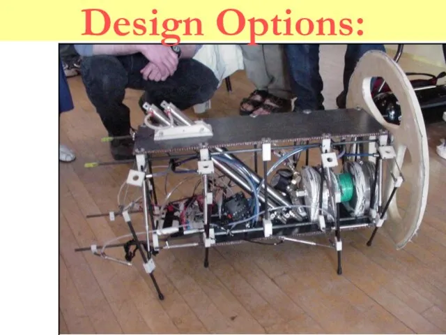
- 116. Design Options:
- 117. Design Options:
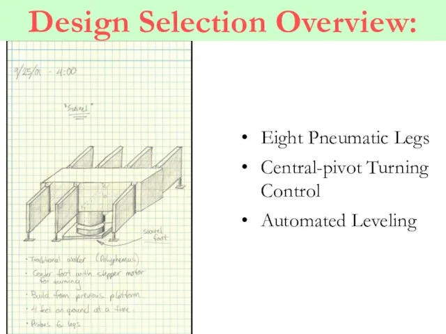
- 118. Design Selection Overview: Eight Pneumatic Legs Central-pivot Turning Control Automated Leveling
- 119. Polyphemus – Conceptual Design Mechanical Vision system constraints Task defined functionality Controls Decision/execution architecture HL –
- 120. Mechanical Design Elements Vision system constraints Stability Consistent height and angle Task defined functionality Negotiating obstacles
- 121. Mechanical Design Solution Pneumatics Low cost and environmentally inert Difficult to control closed-loop Locomotion 8 Legs
- 122. Controls Design Elements Parallel development Architecture High Level Image acquisition Navigation decisions Low Level Mechanical status
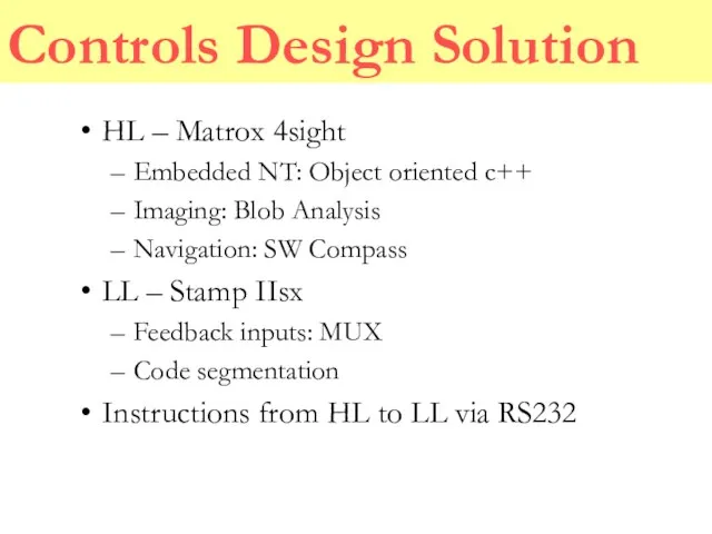
- 123. Controls Design Solution HL – Matrox 4sight Embedded NT: Object oriented c++ Imaging: Blob Analysis Navigation:
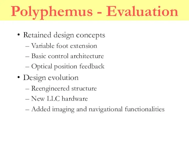
- 124. Polyphemus - Evaluation Retained design concepts Variable foot extension Basic control architecture Optical position feedback Design
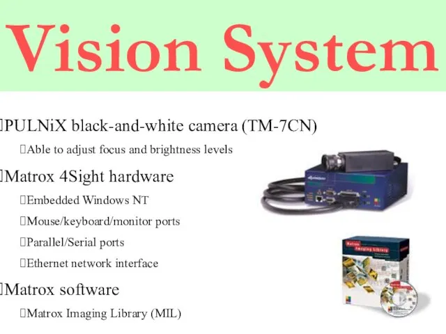
- 125. Vision System PULNiX black-and-white camera (TM-7CN) Able to adjust focus and brightness levels Matrox 4Sight hardware
- 126. Costs of the Components PULNiX camera (TM-7CN) - $793 Matrox 4Sight hardware - $2,470 Matrox software
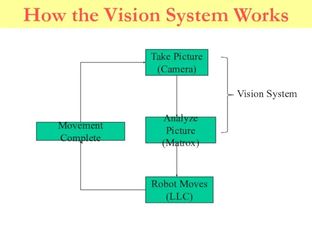
- 127. How the Vision System Works Vision System
- 128. Existing Code C++ Microsoft Visual C++ Coding done in classes More than one person can work
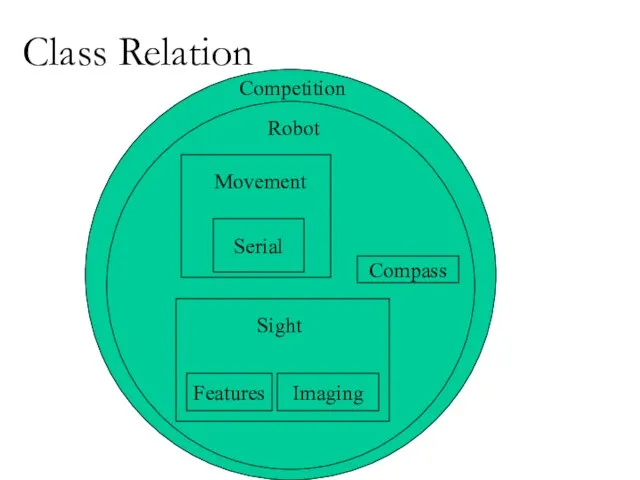
- 129. Class Relation Competition Robot Compass Features Imaging Sight
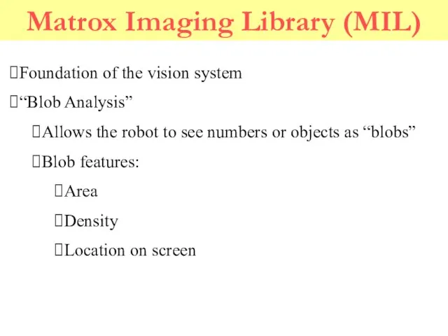
- 130. Matrox Imaging Library (MIL) Foundation of the vision system “Blob Analysis” Allows the robot to see
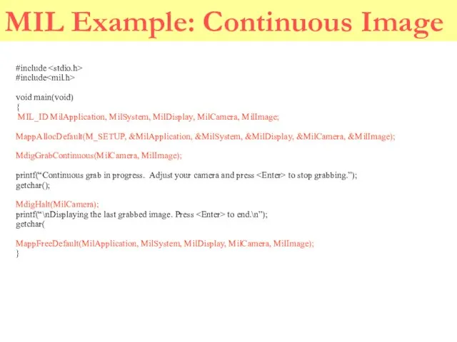
- 131. MIL Example: Continuous Image #include #include void main(void) { MIL_ID MilApplication, MilSystem, MilDisplay, MilCamera, MilImage; MappAllocDefault(M_SETUP,
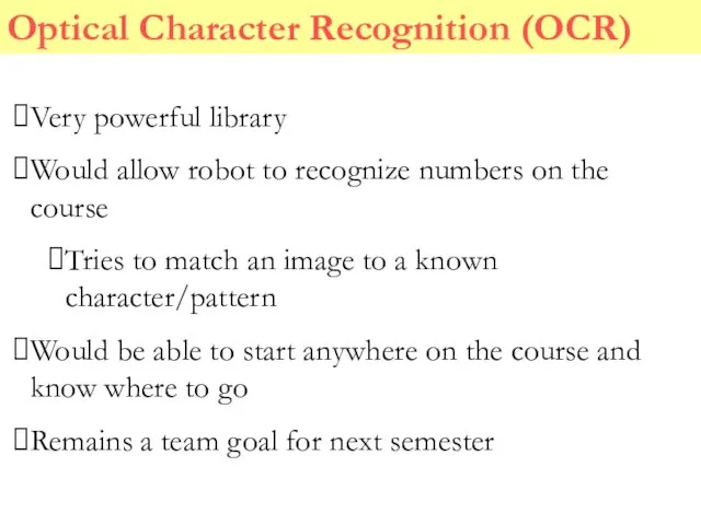
- 132. Optical Character Recognition (OCR) Very powerful library Would allow robot to recognize numbers on the course
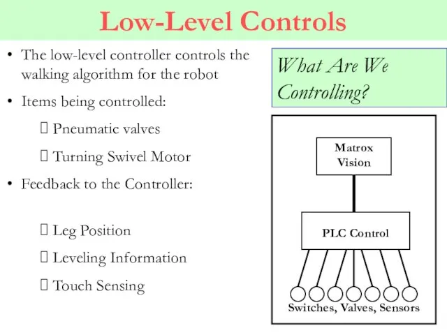
- 133. What Are We Controlling? The low-level controller controls the walking algorithm for the robot Items being
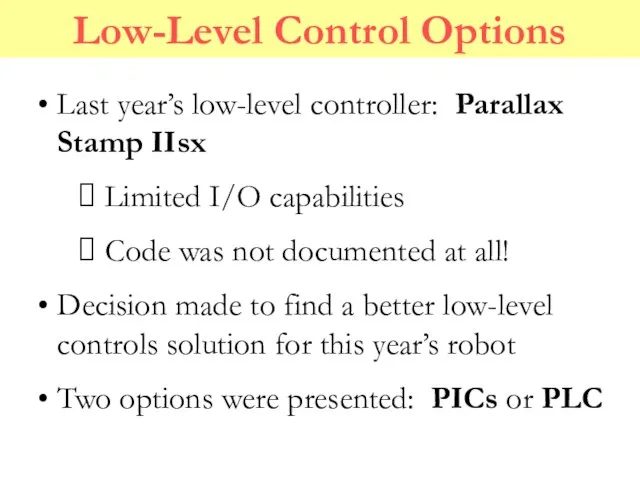
- 134. Low-Level Control Options Last year’s low-level controller: Parallax Stamp IIsx Limited I/O capabilities Code was not
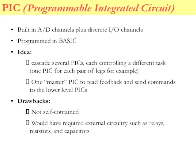
- 135. PIC (Programmable Integrated Circuit) Built in A/D channels plus discrete I/O channels Programmed in BASIC Idea:
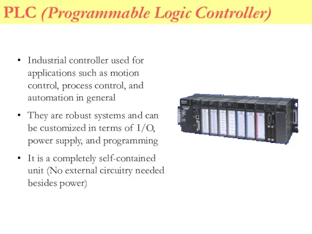
- 136. PLC (Programmable Logic Controller) Industrial controller used for applications such as motion control, process control, and
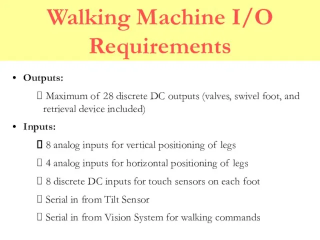
- 137. Walking Machine I/O Requirements Outputs: Maximum of 28 discrete DC outputs (valves, swivel foot, and retrieval
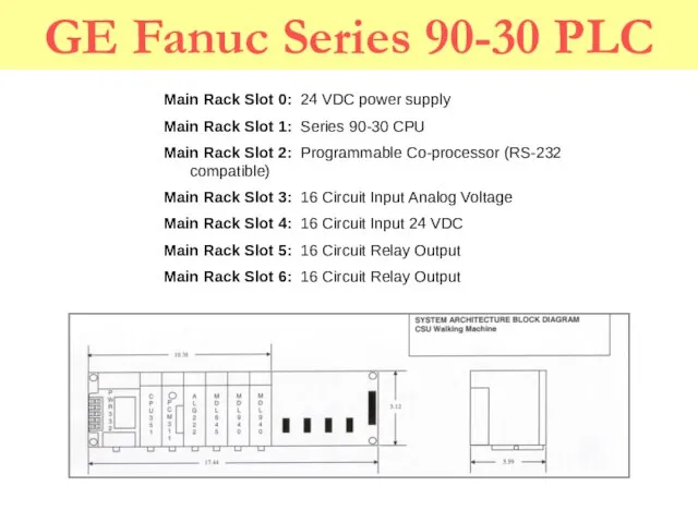
- 138. GE Fanuc Series 90-30 PLC Main Rack Slot 0: 24 VDC power supply Main Rack Slot
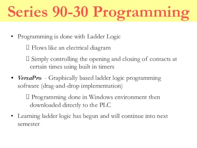
- 139. Series 90-30 Programming Programming is done with Ladder Logic Flows like an electrical diagram Simply controlling
- 140. PLC Cost Analysis Qty Part Number Description Unit Net Extended Net Cables 1 IC690CBL701 Cable, PCM
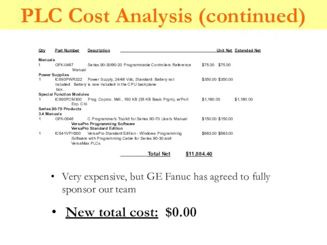
- 141. PLC Cost Analysis (continued) Qty Part Number Description Unit Net Extended Net Manuals GFK-0467 Series 90-30/90-20
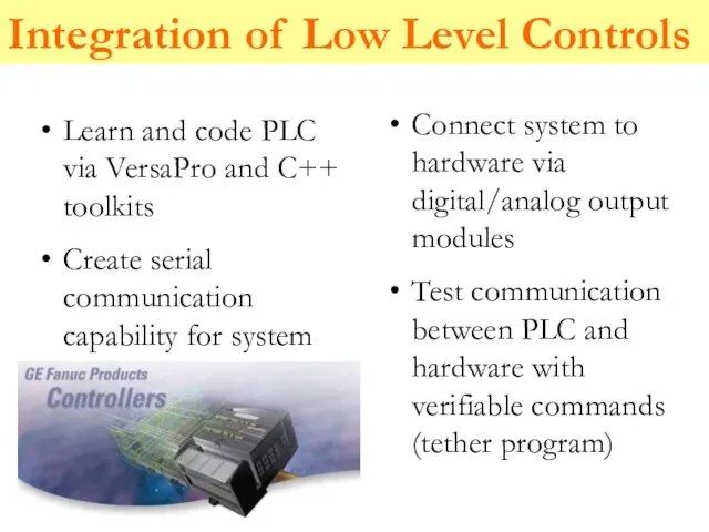
- 142. Integration of Low Level Controls Connect system to hardware via digital/analog output modules Test communication between
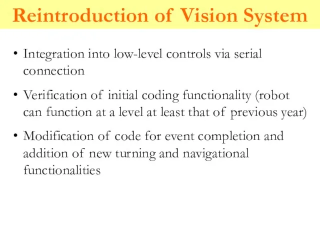
- 143. Reintroduction of Vision System Integration into low-level controls via serial connection Verification of initial coding functionality
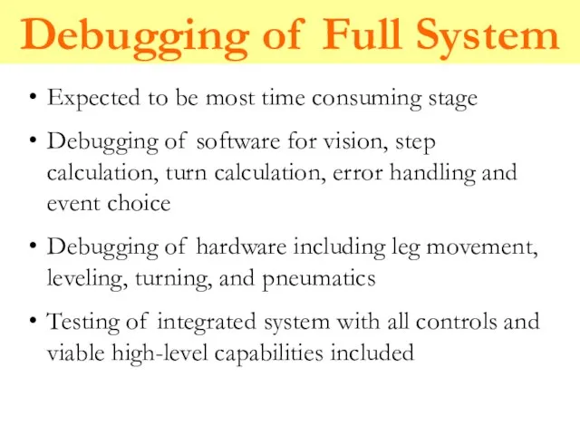
- 144. Debugging of Full System Expected to be most time consuming stage Debugging of software for vision,
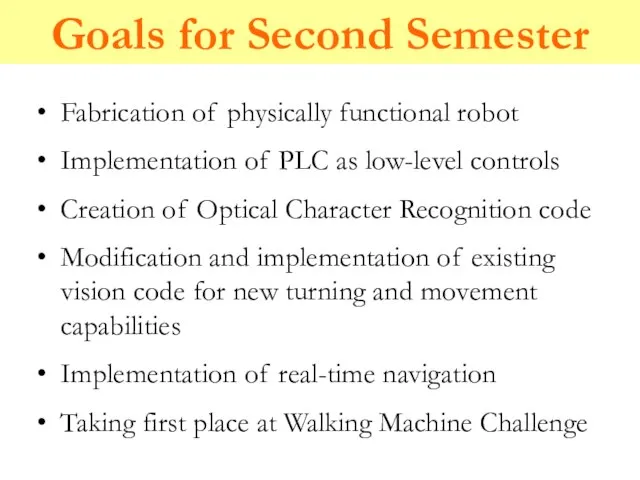
- 145. Goals for Second Semester Fabrication of physically functional robot Implementation of PLC as low-level controls Creation
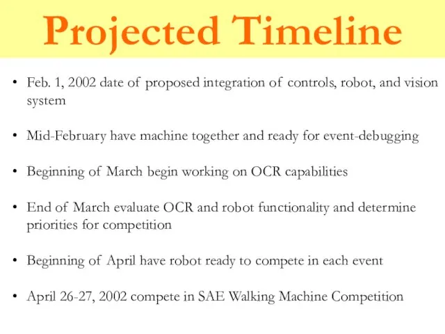
- 146. Projected Timeline Feb. 1, 2002 date of proposed integration of controls, robot, and vision system Mid-February
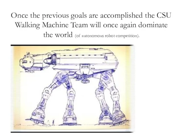
- 147. Once the previous goals are accomplished the CSU Walking Machine Team will once again dominate the
- 148. Problems to Solve for PSU class 1. Give examples of each of the following joints in
- 149. Problems to Solve 1. Describe human hand as a kinematic model. How many degrees of freedom.
- 150. Problems to Solve 7. Describe a holonomic model of human-like simplified hand. 8. Modify it to
- 151. Problems to Solve 12. How to solve practically in the simplest way the inverse kinematics problem
- 153. Скачать презентацию
Слайд 2Robots from Colorado State University
Year Finishes Machine
1986-87 3rd Place
1987-88 1st Place Lurch
1988-89 1st Place Lurch-Next Generation
1989-90 3rd Place Lurch II
1990-91 1st Place Lurch
Robots from Colorado State University
Year Finishes Machine
1986-87 3rd Place
1987-88 1st Place Lurch
1988-89 1st Place Lurch-Next Generation
1989-90 3rd Place Lurch II
1990-91 1st Place Lurch
Слайд 3Design of a Rough Terrain
Vehicle (RTV)
Design of a Rough Terrain
Vehicle (RTV)

Слайд 4LEGO Parts Kits
5201 Connectors
5228/5235 Frame Members
5267 Shafts, Rigid Couplings
5269 Bell Cranks, Misc.
LEGO Parts Kits
5201 Connectors
5228/5235 Frame Members
5267 Shafts, Rigid Couplings
5269 Bell Cranks, Misc.
Слайд 5LEGO Parts Kits
9854 Rack & Pinion Gears
9965 Two sizes, small spur gears
9966
LEGO Parts Kits
9854 Rack & Pinion Gears
9965 Two sizes, small spur gears
9966
Слайд 6Gear/Motor Fundamentals
Spur gears have straight teeth
Used to transmit torque and rotation between
Gear/Motor Fundamentals
Spur gears have straight teeth
Used to transmit torque and rotation between
Слайд 7Gear Fundamentals
Torque times angular velocity is constant between two meshed gears
Angular velocity
Gear Fundamentals
Torque times angular velocity is constant between two meshed gears
Angular velocity
Слайд 8Simple Gear Trains
A Simple Gear Train has one gear per shaft-
Simple Gear Trains
A Simple Gear Train has one gear per shaft-
Слайд 9Compound Gear Trains
A Compound Gear Train has more than one gear on
Compound Gear Trains
A Compound Gear Train has more than one gear on
Слайд 10Worm Gear & Worm
Worm Gear & Worm
Слайд 11Rack & Pinion
Rack & Pinion
Слайд 12Straight Bevel Gears
Straight Bevel Gears

Слайд 13Measuring Legged Locomotion
Walking is similar to rolling a polygon which has the
Measuring Legged Locomotion
Walking is similar to rolling a polygon which has the
Слайд 14Power Required to Walk
Work required to walk is wasted in the consecutive
Power Required to Walk
Work required to walk is wasted in the consecutive
Слайд 16Great History Moments in Legged Locomotion
1837 Weber and Weber Measure corpses and
Great History Moments in Legged Locomotion
1837 Weber and Weber Measure corpses and
Слайд 17The Mechanical Horse
Device patented by Lewis Rygg in 1893
The stirrups double as
The Mechanical Horse
Device patented by Lewis Rygg in 1893
The stirrups double as
Слайд 18Linkage Fundamentals
Linkages are levers of various shapes joined together by joints which
Linkage Fundamentals
Linkages are levers of various shapes joined together by joints which
Слайд 19Linkage Fundamentals
Linkages are normally driven by a short lever
This level is also
Linkage Fundamentals
Linkages are normally driven by a short lever
This level is also
Слайд 20What is a pivot?
A short rod or shaft about which a related
What is a pivot?
A short rod or shaft about which a related
Слайд 21Generating Walking
When input crank AB rotates,
– 1/2 straight path and
1/2 arched path.
Linkages
Generating Walking
When input crank AB rotates,
– 1/2 straight path and
1/2 arched path.
Linkages
Слайд 22What are the types of mechanism chains?
Linkages are levers of various shapes
joined
What are the types of mechanism chains?
Linkages are levers of various shapes
joined
Слайд 23Crank & Rocker
Rocker Pivot
Grashof Crank - Rocker
rotates
Extreme positions
This symbol means it is
Crank & Rocker
Rocker Pivot
Grashof Crank - Rocker
rotates
Extreme positions
This symbol means it is
Слайд 24Rules For Link Lengths
Long +Short Links Crank &
Rules For Link Lengths
Long +Short Links
Слайд 25Walking-Link Crank & Rocker
A four-bar linkage
Triangular extension which supports a shoe which
Walking-Link Crank & Rocker
A four-bar linkage
Triangular extension which supports a shoe which
Слайд 26Equal Link Lengths On Opposite Sides
Equal length
Equal Link Lengths On Opposite Sides
Equal length
Слайд 27Hexapod Six-Legged Robot
Hexapod Six-Legged Robot
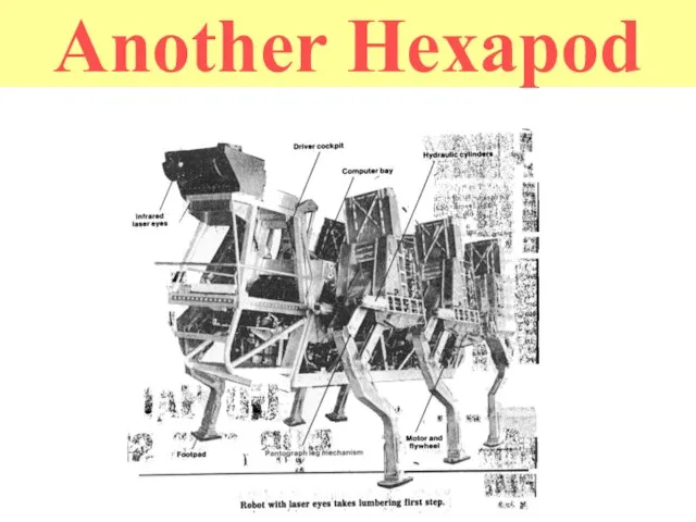
Слайд 28Another Hexapod
Another Hexapod
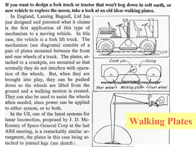
Слайд 29Walking Plates
Walking Plates
Слайд 30More Great History Moments
1983 Odetics demonstrates a self-contained hexapod which lifts and
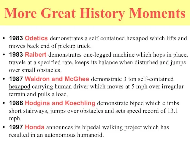
More Great History Moments
1983 Odetics demonstrates a self-contained hexapod which lifts and
Слайд 31Two Legged Vehicle--The P2
Honda Motor Co.
Obstacle Avoidance by stepping over and around.
can
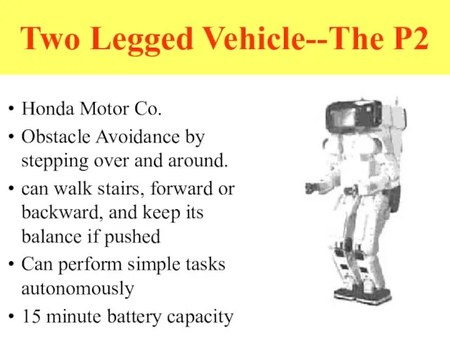
Two Legged Vehicle--The P2
Honda Motor Co.
Obstacle Avoidance by stepping over and around.
can
Слайд 32Hexapods from Lynxmotion
Hexapods from Lynxmotion
Слайд 33Lynxmotion Kits
Hexapods
Cars
Arms
Quadrupeds
Lynxmotion Hexapods
Lynxmotion Kits
Hexapods
Cars
Arms
Quadrupeds
Lynxmotion Hexapods
Слайд 34Basic Radio-Controlled Spider Hexapod with Gripper
Basic Radio-Controlled Spider Hexapod with Gripper
Слайд 35Spider with a camera
Spider with a camera
Слайд 37The Hexapod Kit
Hexapod II Kit (body and 12 servos)
A next step micro
The Hexapod Kit
Hexapod II Kit (body and 12 servos)
A next step micro
Слайд 38Added Wireless Video Camera
Called the XCAM2
Purchased from X10.com
It costs $99.99 with a
Added Wireless Video Camera
Called the XCAM2
Purchased from X10.com
It costs $99.99 with a
Слайд 39Basic Stamp2-SX controller
Microcontroller: Scenix SX28AC
Program execution speed: 10,000 instructions per second
Processor Speed: 50 Mhz
Memory:
Program Memory
Basic Stamp2-SX controller
Microcontroller: Scenix SX28AC
Program execution speed: 10,000 instructions per second
Processor Speed: 50 Mhz
Memory:
Program Memory
Слайд 40Controller continued…
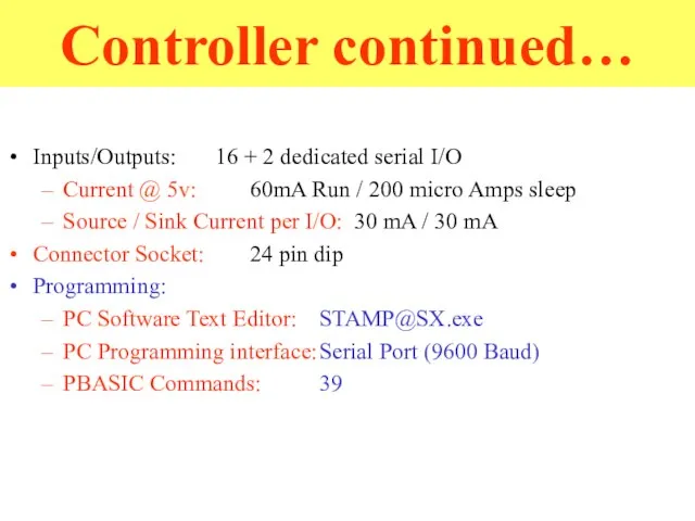
Inputs/Outputs: 16 + 2 dedicated serial I/O
Current @ 5v: 60mA Run / 200
Controller continued…
Inputs/Outputs: 16 + 2 dedicated serial I/O
Current @ 5v: 60mA Run / 200
Слайд 41Next Step Carrier Board
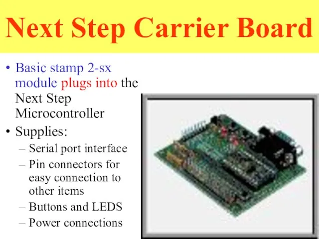
Basic stamp 2-sx module plugs into the Next Step
Next Step Carrier Board
Basic stamp 2-sx module plugs into the Next Step
Слайд 42Component Interconnections
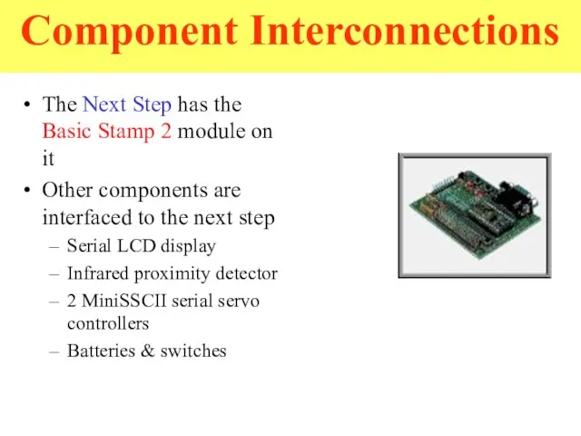
The Next Step has the Basic Stamp 2 module on it
Other
Component Interconnections
The Next Step has the Basic Stamp 2 module on it
Other
Слайд 43Serial LCD Display
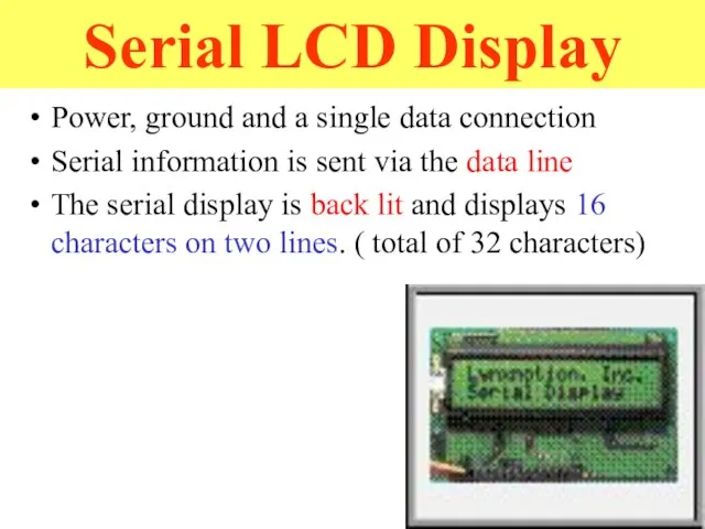
Power, ground and a single data connection
Serial information is sent
Serial LCD Display
Power, ground and a single data connection
Serial information is sent
Слайд 44IRPD
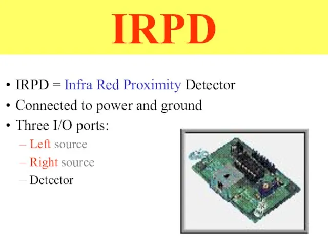
IRPD = Infra Red Proximity Detector
Connected to power and ground
Three I/O ports:
Left
IRPD
IRPD = Infra Red Proximity Detector
Connected to power and ground
Three I/O ports:
Left
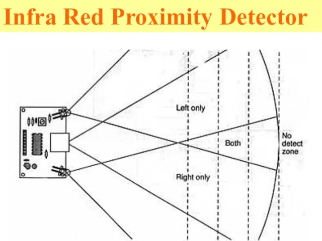
Слайд 45Infra Red Proximity Detector
Infra Red Proximity Detector
Слайд 46MiniSSCII servo controller
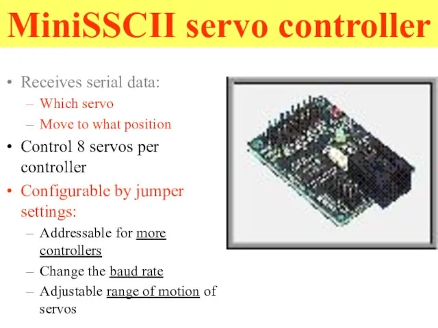
Receives serial data:
Which servo
Move to what position
Control 8 servos
MiniSSCII servo controller
Receives serial data:
Which servo
Move to what position
Control 8 servos
Слайд 47Hexapod II Configuration
Two MiniSSCIIs working together
Six servos per controller:
one controller: 0 to
Hexapod II Configuration
Two MiniSSCIIs working together
Six servos per controller:
one controller: 0 to
Слайд 48Servos
Components:
Electric motor
Gearing
Potentiometer
Difference amplifier
Power amplifier
Servos
Components:
Electric motor
Gearing
Potentiometer
Difference amplifier
Power amplifier
Слайд 49Servo Operation
Potentiometer measures output shaft position
Input signal is sent in
Difference amplifier compares
Servo Operation
Potentiometer measures output shaft position
Input signal is sent in
Difference amplifier compares
Слайд 50Pulse Width Modulation
When “high” for 2mS, stays in right
By controlling the pulse
Pulse Width Modulation
When “high” for 2mS, stays in right
By controlling the pulse
Слайд 51Notable Features
Variable speed
Input signal is pulse width modulation
Pulses ranging from 1 to
Notable Features
Variable speed
Input signal is pulse width modulation
Pulses ranging from 1 to
Слайд 52Batteries & Switches
9 volt battery for the next step
9 volt battery for
Batteries & Switches
9 volt battery for the next step
9 volt battery for

Слайд 57Programming
PBasic programming language
Syntax described in book
Provided text editor
Compiles on PC and downloads
Programming
PBasic programming language
Syntax described in book
Provided text editor
Compiles on PC and downloads
Слайд 58What have we added?
2 Radio frequency transceivers
Computer serial port
Onboard robot
What have we added?
2 Radio frequency transceivers
Computer serial port
Onboard robot
Слайд 59Hexapod Kit Purchasing
The Lynxmotion Hexapod II Professional Edition Combo kit
Their company web
Hexapod Kit Purchasing
The Lynxmotion Hexapod II Professional Edition Combo kit
Their company web
Слайд 60Problems with Lynxmotion hexapods
Weight
Servos make the vehicle quite top heavy and may
Problems with Lynxmotion hexapods
Weight
Servos make the vehicle quite top heavy and may
Слайд 61RHex
RHex
Other Hexapods
RHex
RHex
Other Hexapods
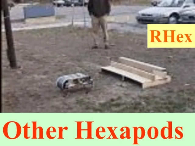
Слайд 62RHex 0 is the first prototype in the RHex series of hexapod
RHex 0 is the first prototype in the RHex series of hexapod
Слайд 64One more hexapod to build
Japanese hexapod
One more hexapod to build
Japanese hexapod
Слайд 65Introduction to Japanese hexapod
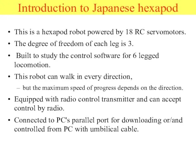
This is a hexapod robot powered by 18 RC
Introduction to Japanese hexapod
This is a hexapod robot powered by 18 RC
Слайд 66Introduction to Japanese hexapod
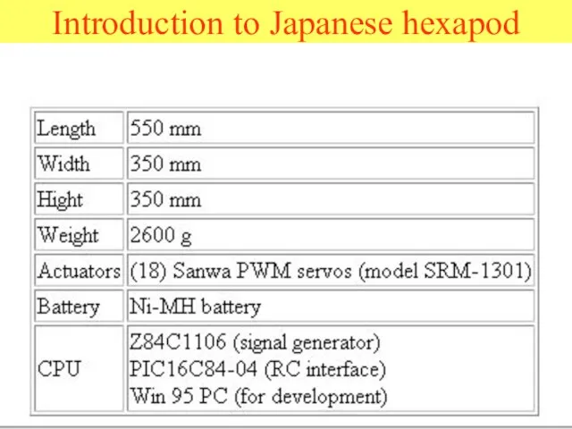
Introduction to Japanese hexapod
Слайд 67Mechanical Structure and Arrangement
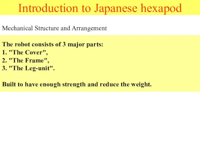
The robot consists of 3 major parts:
1. "The Cover",
Mechanical Structure and Arrangement The robot consists of 3 major parts: 1. "The Cover",
Слайд 68Cover
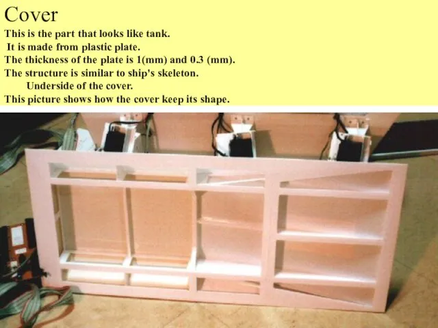
This is the part that looks like tank.
It is made from
Cover This is the part that looks like tank. It is made from
Слайд 69Frame
The frame is made from plastic plate.
(Thickness is 1 mm)
The
Frame The frame is made from plastic plate. (Thickness is 1 mm) The
Слайд 70Leg-unit
Leg-unit
Слайд 71Layout of servomotors
To increase inertia of parts to be actuated is not
Layout of servomotors
To increase inertia of parts to be actuated is not
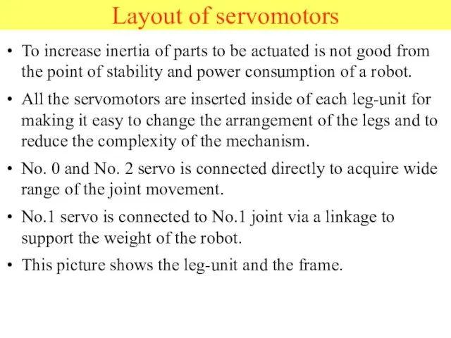
Слайд 73The leg-units were arranged in line not to interfere each other.
When
The leg-units were arranged in line not to interfere each other.
When
Слайд 74All the axles that are opposite side of servomotors have a simple
All the axles that are opposite side of servomotors have a simple
Слайд 75Joint 0
This picture shows how servo 0 is mounted.
Joint 0
This picture shows how servo 0 is mounted.
Слайд 76This picture shows around joint 0. The leg-unit is mounted to the
This picture shows around joint 0. The leg-unit is mounted to the
Слайд 77Joint 1
This picture shows how servo 1 is mounted.
The servo
Joint 1
This picture shows how servo 1 is mounted.
The servo
Слайд 78This picture shows around joint 1.
Use a part for RC car
This picture shows around joint 1.
Use a part for RC car
Слайд 79Joint 2
This picture shows how servo 2 is mounted. The servo
Joint 2
This picture shows how servo 2 is mounted. The servo
Слайд 80This picture shows the opposite side of servo 2.
This picture shows the opposite side of servo 2.
Слайд 81This picture shows the opposite side of servo 2.
The joint is
This picture shows the opposite side of servo 2.
The joint is
Слайд 82This picture shows underside of the leg-unit with no servomotors.
This picture shows underside of the leg-unit with no servomotors.
Слайд 83Reinforce of the joints
These pictures show how leg-unit is reinforced.
The servo-controller
Reinforce of the joints
These pictures show how leg-unit is reinforced.
The servo-controller
Слайд 84Upper part of the joint 0 is reinforced with aluminum plate of
Upper part of the joint 0 is reinforced with aluminum plate of
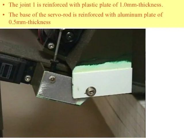
Слайд 85The joint 1 is reinforced with plastic plate of 1.0mm-thickness.
The base
The joint 1 is reinforced with plastic plate of 1.0mm-thickness.
The base
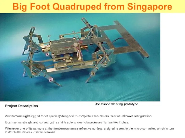
Слайд 86Project Description
Autonomous eight-legged robot specially designed to complete a ten meters track
Project Description
Autonomous eight-legged robot specially designed to complete a ten meters track
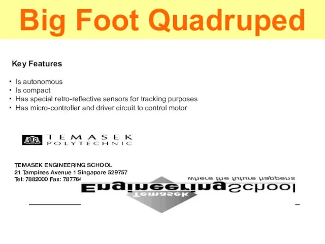
Слайд 87Key Features
Is autonomous
Is compact
Has special retro-reflective sensors for tracking
Key Features
Is autonomous
Is compact
Has special retro-reflective sensors for tracking
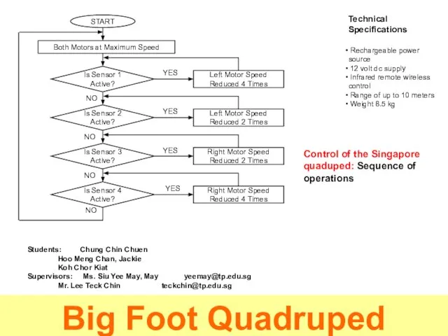
Слайд 88Technical Specifications
Rechargeable power source
12 volt dc supply
Infrared remote wireless
Technical Specifications
Rechargeable power source
12 volt dc supply
Infrared remote wireless
Слайд 89Multi-legged Mobile Robot
Design of the Control System
Adaptation of Mekatronix Hexapod
Multi-legged Mobile Robot
Design of the Control System
Adaptation of Mekatronix Hexapod
Слайд 90Main Purpose
Main Purpose

Слайд 91Design and implement an efficient control system that will allow a six-legged
Design and implement an efficient control system that will allow a six-legged
Слайд 92The Robot
Main Purpose
The Robot
Main Purpose
Слайд 93The Hexa-Pod Autonomous RoboBug
Picture courtesy of Mekatronix: "Copyright 1999"
The Hexa-Pod Autonomous RoboBug
Picture courtesy of Mekatronix: "Copyright 1999"
Слайд 94High Level Performance
Low Level Performance
The Robot
Main Purpose
High Level Performance
Low Level Performance
The Robot
Main Purpose
Слайд 95LOW LEVEL PERFOMANCE
Controlled by Peripheral Interface Controllers
HIGH LEVEL PERFOMANCE
Controlled by Motorola 68HC12
LOW LEVEL PERFOMANCE
Controlled by Peripheral Interface Controllers
HIGH LEVEL PERFOMANCE
Controlled by Motorola 68HC12
Слайд 96Walk Routine
Walk Routine
Слайд 97TRIPOD WALK
FRONT
FRONT
Provides great static & dynamic stability
Fastest & most efficient
TRIPOD WALK
FRONT
FRONT
Provides great static & dynamic stability
Fastest & most efficient
Слайд 98Algorithm Matrix
Algorithm Matrix
Слайд 99Walking Algorithm Matrix
Walking Algorithm Matrix
Слайд 100PIC Networking
PIC Networking
Слайд 101PIC’s Networking Module
Front legs
Middle legs
Rear legs
Ports T0-T4
HC12
PIC’s Networking Module
Front legs
Middle legs
Rear legs
Ports T0-T4
HC12
Слайд 102User Interface
User Interface
Слайд 103User Interface LCD & KeyPad
MOTOROLA
68HC12
Provides global coordinate system
Provides software relieve
User Interface LCD & KeyPad
MOTOROLA
68HC12
Provides global coordinate system
Provides software relieve
Слайд 104Orientation
System
User Interface
Orientation
System
User Interface
Слайд 105Orientation System
Electronic
Compass
Reading
Orientation System
Electronic
Compass
Reading
Слайд 106Navigation
System
Orientation
System
User Interface
Navigation
System
Orientation
System
User Interface
Слайд 107Navigation System
X
Y
Initialize Coordinates
N
S
E
W
Read Orientation
Step Cycle
Line Detected
Fix Position
no
yes
Navigation System
X
Y
Initialize Coordinates
N
S
E
W
Read Orientation
Step Cycle
Line Detected
Fix Position
no
yes
Слайд 108Navigation
System
Sensors System
User Interface
Navigation
System
Sensors System
User Interface
Слайд 109Sensors System
Sensors System
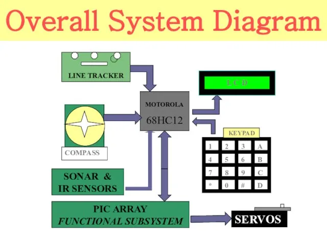
Слайд 110Overall System Diagram
SONAR &
IR SENSORS
MOTOROLA
68HC12
1
2
C
3
6
9
B
A
8
5
4
7
*
0
#
D
KEYPAD
LINE TRACKER
COMPASS
PIC ARRAY
FUNCTIONAL SUBSYSTEM
Overall System Diagram
SONAR &
IR SENSORS
MOTOROLA
68HC12
1
2
C
3
6
9
B
A
8
5
4
7
*
0
#
D
KEYPAD
LINE TRACKER
COMPASS
PIC ARRAY
FUNCTIONAL SUBSYSTEM
Слайд 111WMC Competition Overview
WMC Competition Overview

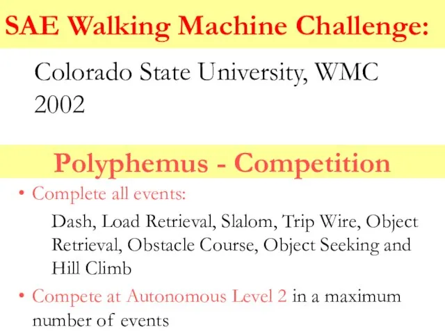
Слайд 112Polyphemus - Competition
Complete all events:
Dash, Load Retrieval, Slalom, Trip Wire, Object Retrieval,
Polyphemus - Competition
Complete all events:
Dash, Load Retrieval, Slalom, Trip Wire, Object Retrieval,
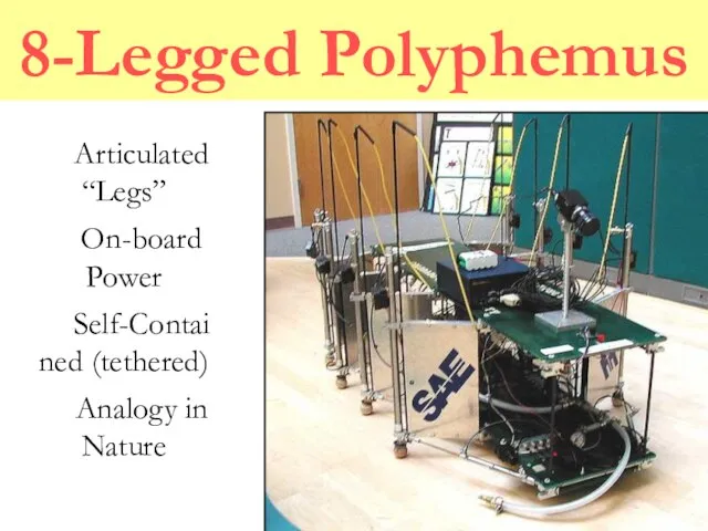
Слайд 1138-Legged Polyphemus
Articulated “Legs”
On-board Power
Self-Contained (tethered)
Analogy in Nature
8-Legged Polyphemus
Articulated “Legs”
On-board Power
Self-Contained (tethered)
Analogy in Nature
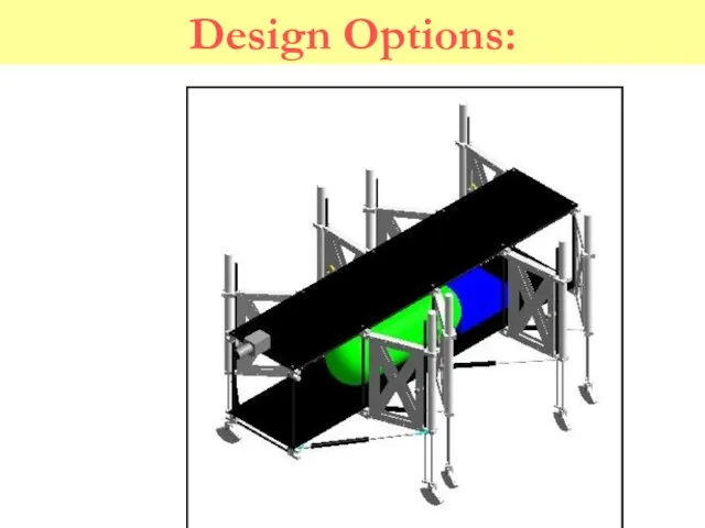
Слайд 114Design Options:
Design Options:
Слайд 115Design Options:
Design Options:
Слайд 116Design Options:
Design Options:
Слайд 117Design Options:
Design Options:
Слайд 118Design Selection Overview:
Eight Pneumatic Legs
Central-pivot Turning Control
Automated Leveling
Design Selection Overview:
Eight Pneumatic Legs
Central-pivot Turning Control
Automated Leveling
Слайд 119Polyphemus – Conceptual Design
Mechanical
Vision system constraints
Task defined functionality
Controls
Decision/execution architecture
HL – navigation
LL –
Polyphemus – Conceptual Design
Mechanical
Vision system constraints
Task defined functionality
Controls
Decision/execution architecture
HL – navigation
LL –
Слайд 120Mechanical Design Elements
Vision system constraints
Stability
Consistent height and angle
Task defined functionality
Negotiating obstacles
Repeatable steps
Mechanical Design Elements
Vision system constraints
Stability
Consistent height and angle
Task defined functionality
Negotiating obstacles
Repeatable steps
Слайд 121Mechanical Design Solution
Pneumatics
Low cost and environmentally inert
Difficult to control closed-loop
Locomotion
8 Legs –
Mechanical Design Solution
Pneumatics
Low cost and environmentally inert
Difficult to control closed-loop
Locomotion
8 Legs –
Слайд 122Controls Design Elements
Parallel development
Architecture
High Level
Image acquisition
Navigation decisions
Low Level
Mechanical status and control
Maneuver execution
Controls Design Elements
Parallel development
Architecture
High Level
Image acquisition
Navigation decisions
Low Level
Mechanical status and control
Maneuver execution
Слайд 123Controls Design Solution
HL – Matrox 4sight
Embedded NT: Object oriented c++
Imaging: Blob Analysis
Navigation:
Controls Design Solution
HL – Matrox 4sight
Embedded NT: Object oriented c++
Imaging: Blob Analysis
Navigation:
Слайд 124Polyphemus - Evaluation
Retained design concepts
Variable foot extension
Basic control architecture
Optical position feedback
Design evolution
Reengineered
Polyphemus - Evaluation
Retained design concepts
Variable foot extension
Basic control architecture
Optical position feedback
Design evolution
Reengineered
Слайд 125Vision System
PULNiX black-and-white camera (TM-7CN)
Able to adjust focus and brightness levels
Matrox 4Sight
Vision System
PULNiX black-and-white camera (TM-7CN)
Able to adjust focus and brightness levels
Matrox 4Sight
Слайд 126Costs of the Components
PULNiX camera (TM-7CN) - $793
Matrox 4Sight hardware - $2,470
Matrox
Costs of the Components
PULNiX camera (TM-7CN) - $793
Matrox 4Sight hardware - $2,470
Matrox
Слайд 127How the Vision System Works
Vision System
How the Vision System Works
Vision System
Слайд 128Existing Code
C++
Microsoft Visual C++
Coding done in classes
More than one person can work
Existing Code
C++
Microsoft Visual C++
Coding done in classes
More than one person can work
Слайд 129Class Relation
Competition
Robot
Compass
Features
Imaging
Sight
Class Relation
Competition
Robot
Compass
Features
Imaging
Sight
Слайд 130Matrox Imaging Library (MIL)
Foundation of the vision system
“Blob Analysis”
Allows the robot to
Matrox Imaging Library (MIL)
Foundation of the vision system
“Blob Analysis”
Allows the robot to
Слайд 131MIL Example: Continuous Image
#include
#include
void main(void)
{
MIL_ID MilApplication, MilSystem, MilDisplay, MilCamera, MilImage;
MappAllocDefault(M_SETUP,
MIL Example: Continuous Image
#include
#include
void main(void)
{
MIL_ID MilApplication, MilSystem, MilDisplay, MilCamera, MilImage;
MappAllocDefault(M_SETUP,
Слайд 132Optical Character Recognition (OCR)
Very powerful library
Would allow robot to recognize numbers on
Optical Character Recognition (OCR)
Very powerful library
Would allow robot to recognize numbers on
Слайд 133What Are We Controlling?
The low-level controller controls the walking algorithm for the
What Are We Controlling?
The low-level controller controls the walking algorithm for the
Слайд 134Low-Level Control Options
Last year’s low-level controller: Parallax Stamp IIsx
Limited I/O capabilities
Low-Level Control Options
Last year’s low-level controller: Parallax Stamp IIsx
Limited I/O capabilities
Слайд 135PIC (Programmable Integrated Circuit)
Built in A/D channels plus discrete I/O channels
Programmed in
PIC (Programmable Integrated Circuit)
Built in A/D channels plus discrete I/O channels
Programmed in
Слайд 136PLC (Programmable Logic Controller)
Industrial controller used for applications such as motion control,
PLC (Programmable Logic Controller)
Industrial controller used for applications such as motion control,
Слайд 137Walking Machine I/O Requirements
Outputs:
Maximum of 28 discrete DC outputs (valves, swivel
Walking Machine I/O Requirements
Outputs:
Maximum of 28 discrete DC outputs (valves, swivel
Слайд 138GE Fanuc Series 90-30 PLC
Main Rack Slot 0: 24 VDC power supply
Main
GE Fanuc Series 90-30 PLC
Main Rack Slot 0: 24 VDC power supply
Main
Слайд 139Series 90-30 Programming
Programming is done with Ladder Logic
Flows like an electrical
Series 90-30 Programming
Programming is done with Ladder Logic
Flows like an electrical
Слайд 140PLC Cost Analysis
Qty Part Number Description Unit Net Extended Net
Cables
1 IC690CBL701 Cable, PCM to IBM-PC/XT Class Computers,
PLC Cost Analysis
Qty Part Number Description Unit Net Extended Net
Cables
1 IC690CBL701 Cable, PCM to IBM-PC/XT Class Computers,

Слайд 141PLC Cost Analysis (continued)
Qty Part Number Description Unit Net Extended Net
Manuals
GFK-0467 Series 90-30/90-20 Programmable Controllers Reference $75.00 $75.00
PLC Cost Analysis (continued)
Qty Part Number Description Unit Net Extended Net
Manuals
GFK-0467 Series 90-30/90-20 Programmable Controllers Reference $75.00 $75.00
Слайд 142Integration of Low Level Controls
Connect system to hardware via digital/analog output modules
Test
Integration of Low Level Controls
Connect system to hardware via digital/analog output modules
Test
Слайд 143Reintroduction of Vision System
Integration into low-level controls via serial connection
Verification of initial
Reintroduction of Vision System
Integration into low-level controls via serial connection
Verification of initial
Слайд 144Debugging of Full System
Expected to be most time consuming stage
Debugging of software
Debugging of Full System
Expected to be most time consuming stage
Debugging of software
Слайд 145Goals for Second Semester
Fabrication of physically functional robot
Implementation of PLC as low-level
Goals for Second Semester
Fabrication of physically functional robot
Implementation of PLC as low-level
Слайд 146Projected Timeline
Feb. 1, 2002 date of proposed integration of controls, robot, and
Projected Timeline
Feb. 1, 2002 date of proposed integration of controls, robot, and
Слайд 147Once the previous goals are accomplished the CSU Walking Machine Team will
Once the previous goals are accomplished the CSU Walking Machine Team will
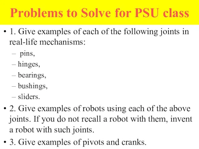
Слайд 148Problems to Solve for PSU class
1. Give examples of each of the
Problems to Solve for PSU class
1. Give examples of each of the
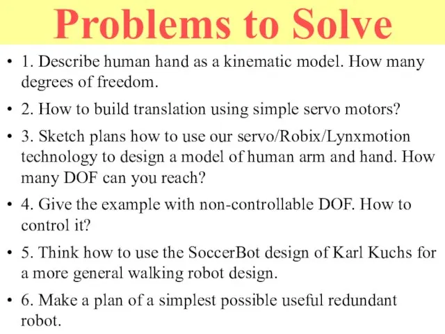
Слайд 149Problems to Solve
1. Describe human hand as a kinematic model. How many
Problems to Solve
1. Describe human hand as a kinematic model. How many
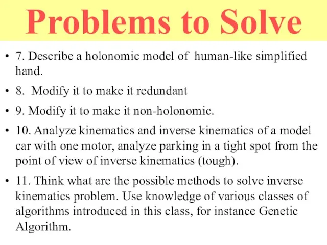
Слайд 150Problems to Solve
7. Describe a holonomic model of human-like simplified hand.
8. Modify
Problems to Solve
7. Describe a holonomic model of human-like simplified hand.
8. Modify
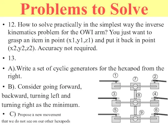
Слайд 151Problems to Solve
12. How to solve practically in the simplest way the
Problems to Solve
12. How to solve practically in the simplest way the
 Тестовые задания по окружающему миру
 Презентация на тему Особенности изменения существительных на -ие, -ия, -ий
  Операторы видеонаблюдения. Питеравто — холдинговая транспортная компания
 Ваш личный имиджмейкер
 Какие бывают финансовые риски
 Река Амазонка
 Почему до сих пор мы применяем в своей речи «крылатые» выражения древних греков? Объясни словосочетание.
 Физическая культура
 Презентация на тему Конструирование и моделирование плечевого изделия
  Тема урока: Признаки равенства треугольников.
 Продукты Oxygen Assistance
 Планирование закупок
 Презентация на тему Склонение имен существительных
  Породы Собак
 Спецрисунок и художественная графика. Рисунок головы
 Cultural regions of America
 Советские деньги
 Электроэнергетика
 Динамика развития РММ в цифрах: выход из штопора, переход в устойчивый плюс
 Полное рекламное обслуживание Акционерного коммерческого банка «АК БАРС»
 Презентация на тему Первая русская революция 1905-1907 гг.
  Школьная адаптация первоклассника, как психолого-педагогическая проблема обучения
 Сочинение – описание животного. Моя собака Крош
 Пушкинская усадьба в Болдино
 Мониторинг удовлетворенности потребителей образовательных услуг ГБОУ ВПО Первый МГМУ им. И.М.Сеченова Минздравсоцразвития Росси
 Презентация на тему Табличный процессор EXCEL
 Волшебные сказки
 Божественные свойства и их именования