- Cp2000 series training notes

Содержание
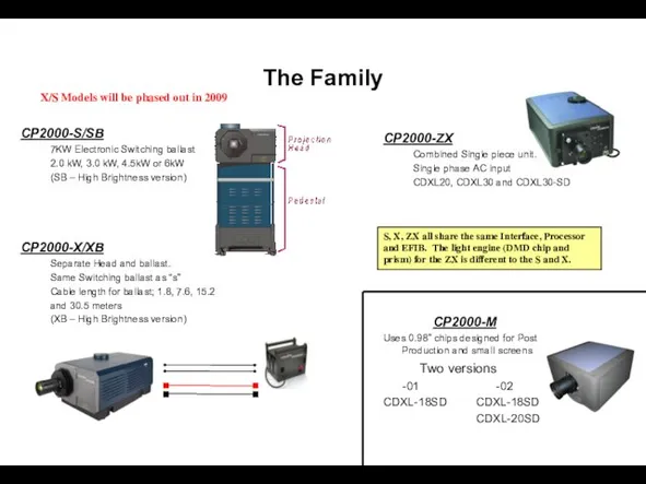
- 3. The Family CP2000-S/SB 7KW Electronic Switching ballast 2.0 kW, 3.0 kW, 4.5kW or 6kW (SB –
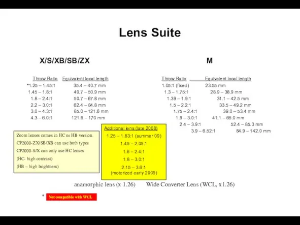
- 4. Lens Suite X/S/XB/SB/ZX Throw Ratio Equivalent local length *1.25 – 1.45:1 35.4 – 40.7 mm 1.45
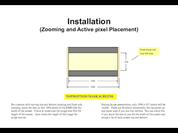
- 5. Installation (Zooming and Active pixel Placement) For cinemas with moving top and bottom masking and fixed
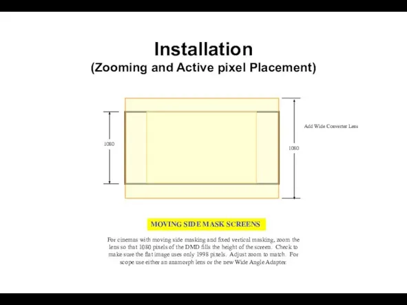
- 6. Installation (Zooming and Active pixel Placement) For cinemas with moving side masking and fixed vertical masking,
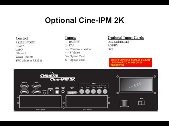
- 7. Optional Cine-IPM 2K Control RS232 IN/OUT RS422 GPIO Ethernet Wired Remote TPC (via rear RS232) Inputs
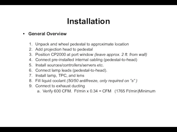
- 8. Installation General Overview Unpack and wheel pedestal to approximate location Add projection head to pedestal Position
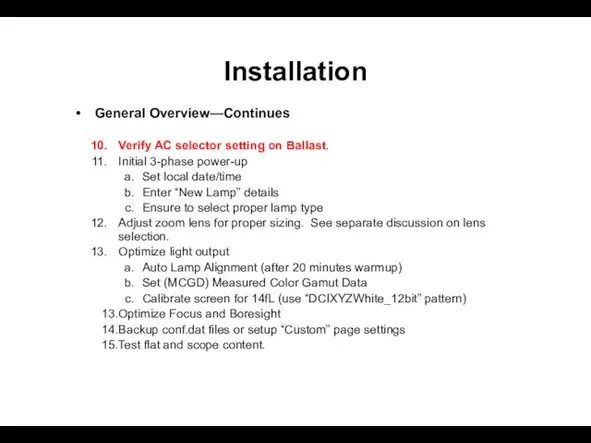
- 9. Installation General Overview—Continues Verify AC selector setting on Ballast. Initial 3-phase power-up Set local date/time Enter
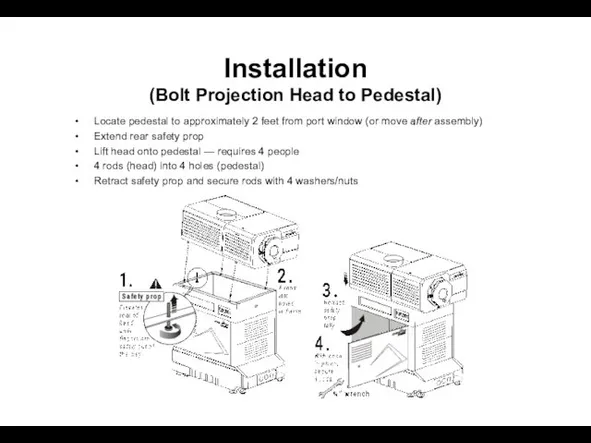
- 10. Installation (Bolt Projection Head to Pedestal) Locate pedestal to approximately 2 feet from port window (or
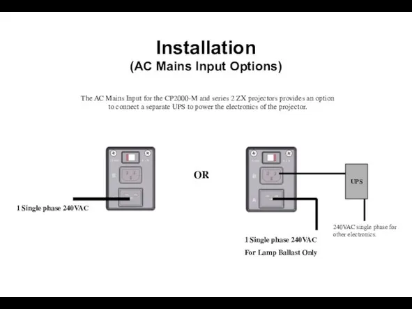
- 11. 1 Single phase 240VAC 1 Single phase 240VAC For Lamp Ballast Only UPS 240VAC single phase
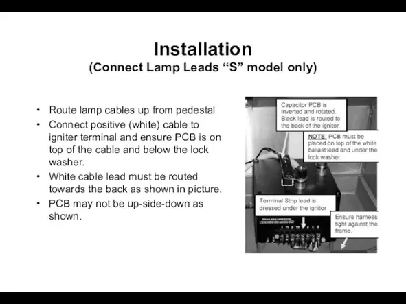
- 12. Installation (Connect Lamp Leads “S” model only) Route lamp cables up from pedestal Connect positive (white)
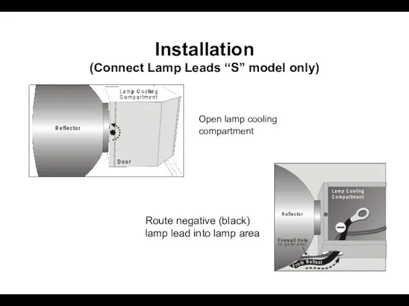
- 13. Installation (Connect Lamp Leads “S” model only) Open lamp cooling compartment Route negative (black) lamp lead
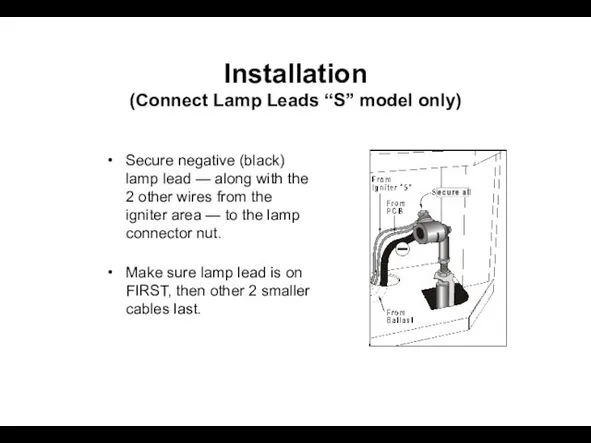
- 14. Installation (Connect Lamp Leads “S” model only) Secure negative (black) lamp lead — along with the
- 15. Installation (Installing Lamp ) CP2000-X/S CP2000-ZX
- 16. Installation (Install Lamp) Secure lamp at cathode Slip anode connector on and secure ! Allen head
- 17. Installation (Connect Water hoses) NOTE:
- 18. Installation (Fill Reservoir, required for Pedestal Units only) Fill completely — no need to watch gauge
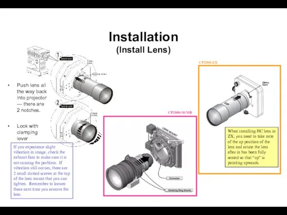
- 19. Installation (Install Lens) Push lens all the way back into projector — there are 2 notches.
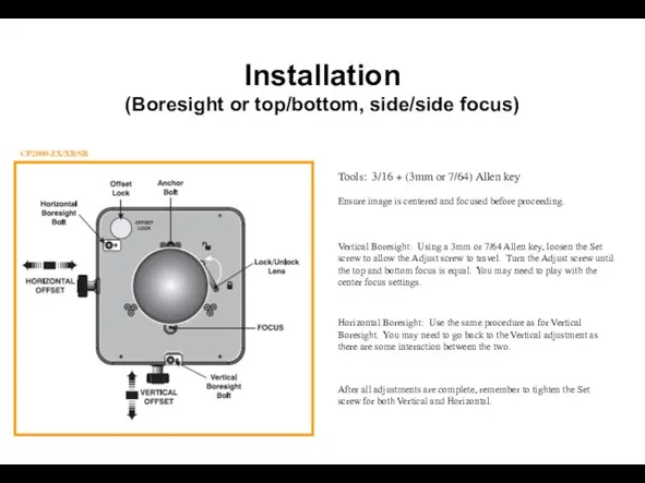
- 20. Installation (Boresight or top/bottom, side/side focus) CP2000-ZX/XB/SB Tools: 3/16 + (3mm or 7/64) Allen key Ensure
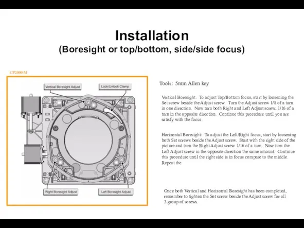
- 21. Installation (Boresight or top/bottom, side/side focus) CP2000-M Tools: 5mm Allen key Vertical Boresight: To adjust Top/Bottom
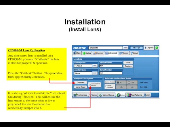
- 22. Installation (Install Lens) CP2000-M Lens Calibration Any time a new lens is installed on a CP2000-M,
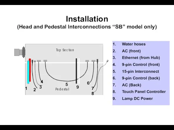
- 23. Installation (Head and Pedestal Interconnections “SB” model only) 1 2 3 4 5 6 Water hoses
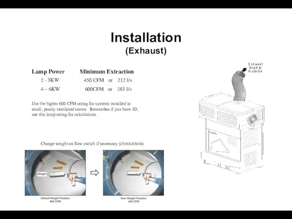
- 24. Installation (Exhaust) Use the higher 600 CFM rating for systems installed in small, poorly ventilated rooms.
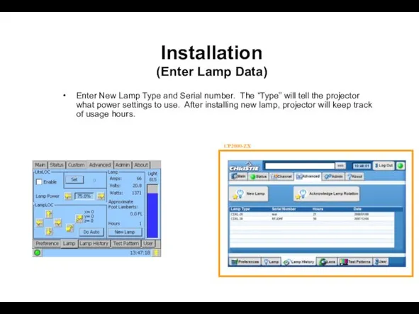
- 25. Installation (Enter Lamp Data) Enter New Lamp Type and Serial number. The “Type” will tell the
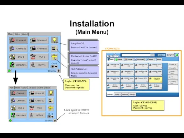
- 26. Login: (CP2000-X/S) User = service Password = tpccds Click again to remove advanced features Installation (Main
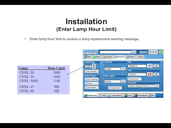
- 27. Installation (Enter Lamp Hour Limit) Enter lamp hour limit to receive a lamp replacement warning message.
- 28. Use Cinema Path for all D-Cinema sources. Data Format: 422 Unpacked 10Bit, O/E Pixels 422 Unpacked
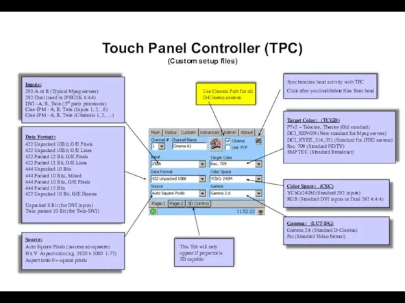
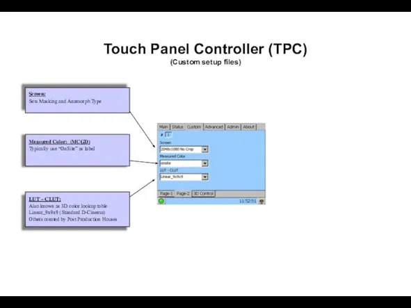
- 29. Touch Panel Controller (TPC) (Custom setup files)
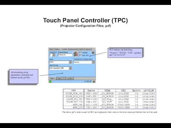
- 30. Touch Panel Controller (TPC) (Projector Configuration Files; pcf) The above pcf’s were issued by DCI and
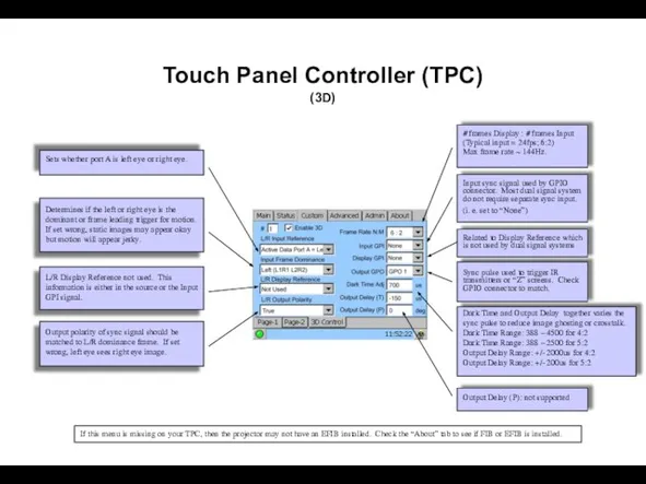
- 31. Touch Panel Controller (TPC) (3D) Input sync signal used by GPIO connector. Most dual signal system
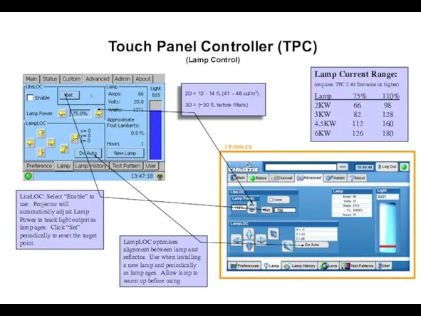
- 32. Lamp Current Range: (requires TPC 2.4d firmware or higher) Lamp 75% 110% 2KW 66 98 3KW
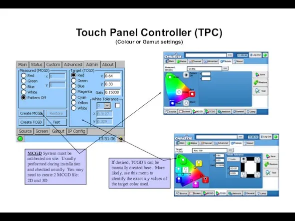
- 33. Touch Panel Controller (TPC) (Colour or Gamut settings) MCGD System must be calibrated on site. Usually
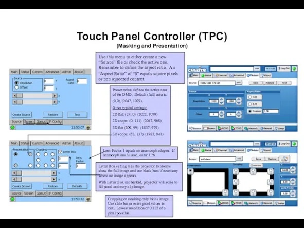
- 34. Touch Panel Controller (TPC) (Masking and Presentation) Use this menu to either create a new “Source”
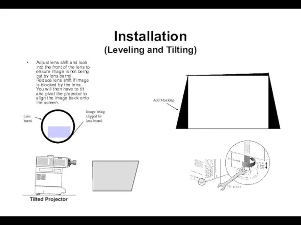
- 35. Installation (Leveling and Tilting) Adjust lens shift and look into the front of the lens to
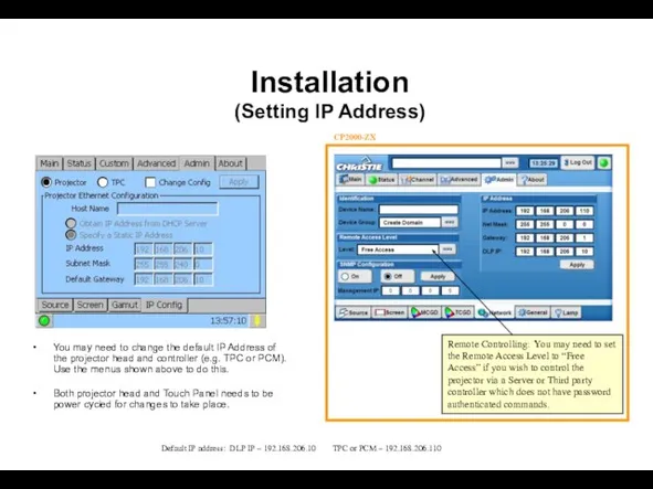
- 36. Installation (Setting IP Address) You may need to change the default IP Address of the projector
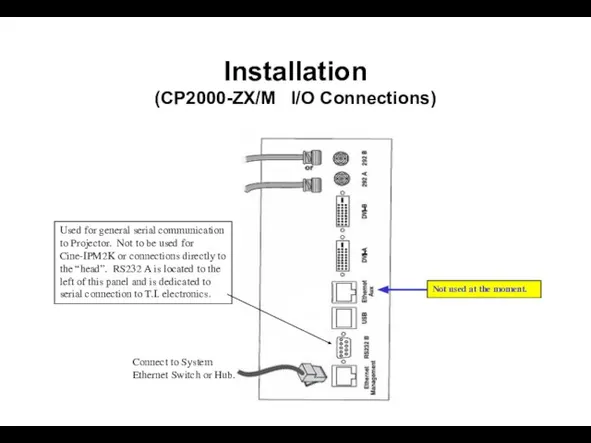
- 37. Installation (CP2000-ZX/M I/O Connections) Not used at the moment. Connect to System Ethernet Switch or Hub.
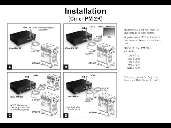
- 38. Installation (Cine-IPM 2K) Projectors with FIB will loose 15 lines top and 15 lines bottom. Projectors
- 39. Maintenance
- 40. Maintenance (Proper Cooling) Standard precautions Avoid crowding with other equipment Keep louvers & vents clear and
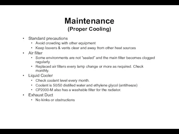
- 41. Electrical: AC connections Check every 60 days or 500 hours: Contact surfaces of anode and cathode
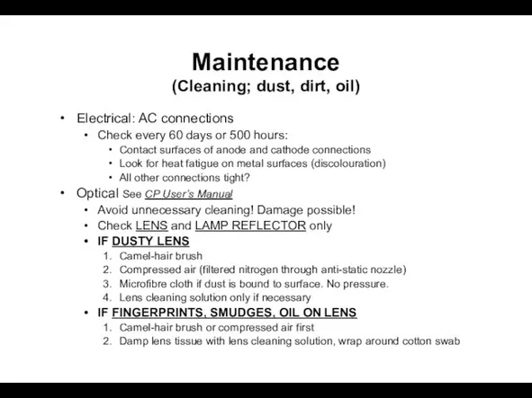
- 42. Optical Continued Other Cleaning Lamp fan Igniter Air flow interlocks (lamp fan and exhaust opening) Maintenance
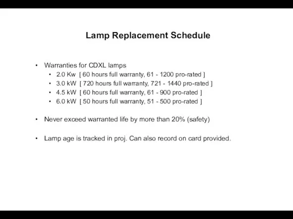
- 43. Lamp Replacement Schedule Warranties for CDXL lamps 2.0 Kw [ 60 hours full warranty, 61 -
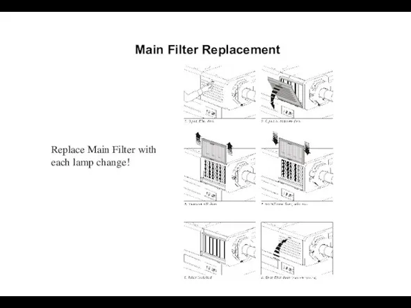
- 44. Main Filter Replacement Replace Main Filter with each lamp change!
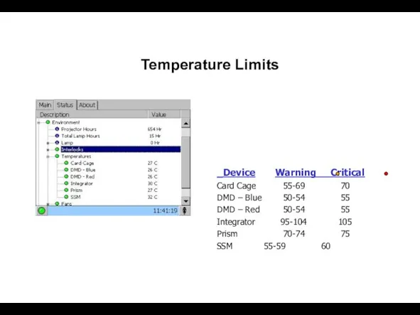
- 45. Temperature Limits Device Warning Critical Card Cage 55-69 70 DMD – Blue 50-54 55 DMD –
- 49. Скачать презентацию

Слайд 3The Family
CP2000-S/SB
7KW Electronic Switching ballast
2.0 kW, 3.0 kW, 4.5kW or 6kW
(SB –
The Family
CP2000-S/SB
7KW Electronic Switching ballast
2.0 kW, 3.0 kW, 4.5kW or 6kW
(SB –
Слайд 4Lens Suite
X/S/XB/SB/ZX
Throw Ratio Equivalent local length
*1.25 – 1.45:1 35.4 – 40.7
Lens Suite
X/S/XB/SB/ZX
Throw Ratio Equivalent local length
*1.25 – 1.45:1 35.4 – 40.7
Слайд 5Installation
(Zooming and Active pixel Placement)
For cinemas with moving top and bottom masking
Installation
(Zooming and Active pixel Placement)
For cinemas with moving top and bottom masking
Слайд 6Installation
(Zooming and Active pixel Placement)
For cinemas with moving side masking and fixed
Installation
(Zooming and Active pixel Placement)
For cinemas with moving side masking and fixed
Слайд 7Optional Cine-IPM 2K
Control
RS232 IN/OUT
RS422
GPIO
Ethernet
Wired Remote
TPC (via rear RS232)
Inputs
1 - RGBHV
2 - DVI
3
Optional Cine-IPM 2K
Control
RS232 IN/OUT
RS422
GPIO
Ethernet
Wired Remote
TPC (via rear RS232)
Inputs
1 - RGBHV
2 - DVI
3
Слайд 8Installation
General Overview
Unpack and wheel pedestal to approximate location
Add projection head to pedestal
Position
Installation
General Overview
Unpack and wheel pedestal to approximate location
Add projection head to pedestal
Position
Слайд 9Installation
General Overview—Continues
Verify AC selector setting on Ballast.
Initial 3-phase power-up
Set local date/time
Enter
Installation
General Overview—Continues
Verify AC selector setting on Ballast.
Initial 3-phase power-up
Set local date/time
Enter
Слайд 10Installation
(Bolt Projection Head to Pedestal)
Locate pedestal to approximately 2 feet from port
Installation
(Bolt Projection Head to Pedestal)
Locate pedestal to approximately 2 feet from port
Слайд 111 Single phase 240VAC
1 Single phase 240VAC
For Lamp Ballast Only
UPS
240VAC single phase
1 Single phase 240VAC
1 Single phase 240VAC
For Lamp Ballast Only
UPS
240VAC single phase
Слайд 12Installation
(Connect Lamp Leads “S” model only)
Route lamp cables up from pedestal
Connect positive
Installation
(Connect Lamp Leads “S” model only)
Route lamp cables up from pedestal
Connect positive
Слайд 13Installation
(Connect Lamp Leads “S” model only)
Open lamp cooling
compartment
Route negative (black)
lamp lead into
Installation
(Connect Lamp Leads “S” model only)
Open lamp cooling
compartment
Route negative (black)
lamp lead into
Слайд 14Installation
(Connect Lamp Leads “S” model only)
Secure negative (black) lamp lead — along
Installation
(Connect Lamp Leads “S” model only)
Secure negative (black) lamp lead — along
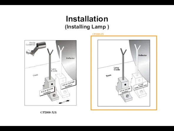
Слайд 15Installation
(Installing Lamp )
CP2000-X/S
CP2000-ZX
Installation
(Installing Lamp )
CP2000-X/S
CP2000-ZX
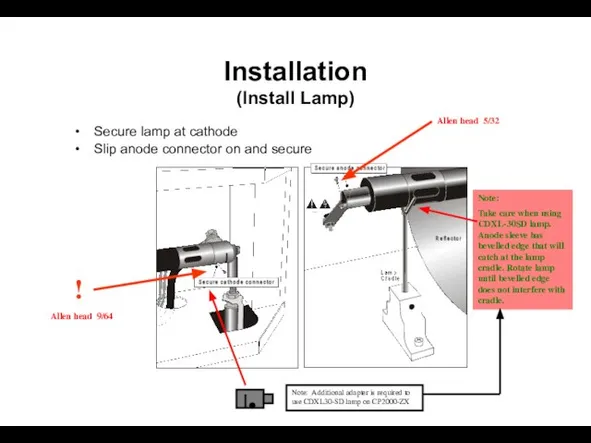
Слайд 16Installation
(Install Lamp)
Secure lamp at cathode
Slip anode connector on and secure
!
Allen head 9/64
Note:
Installation
(Install Lamp)
Secure lamp at cathode
Slip anode connector on and secure
!
Allen head 9/64
Note:
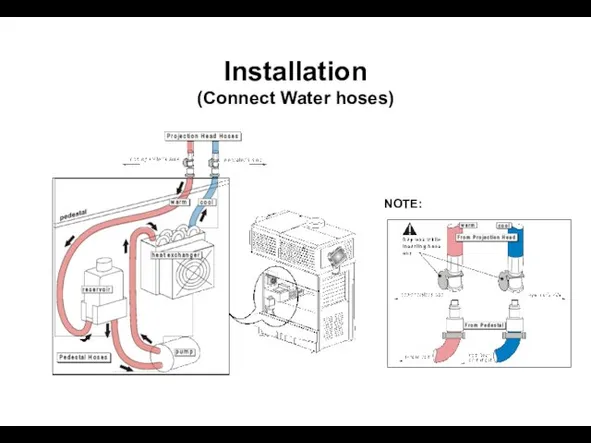
Слайд 17Installation
(Connect Water hoses)
NOTE:
Installation
(Connect Water hoses)
NOTE:
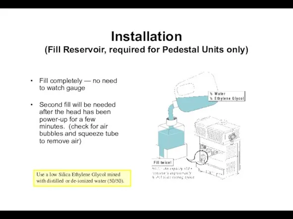
Слайд 18Installation
(Fill Reservoir, required for Pedestal Units only)
Fill completely — no need to
Installation
(Fill Reservoir, required for Pedestal Units only)
Fill completely — no need to
Слайд 19Installation
(Install Lens)
Push lens all the way back into projector — there are
Installation
(Install Lens)
Push lens all the way back into projector — there are
Слайд 20Installation
(Boresight or top/bottom, side/side focus)
CP2000-ZX/XB/SB
Tools: 3/16 + (3mm or 7/64) Allen key
Ensure
Installation
(Boresight or top/bottom, side/side focus)
CP2000-ZX/XB/SB
Tools: 3/16 + (3mm or 7/64) Allen key
Ensure
Слайд 21Installation
(Boresight or top/bottom, side/side focus)
CP2000-M
Tools: 5mm Allen key
Vertical Boresight: To adjust Top/Bottom
Installation
(Boresight or top/bottom, side/side focus)
CP2000-M
Tools: 5mm Allen key
Vertical Boresight: To adjust Top/Bottom
Слайд 22Installation
(Install Lens)
CP2000-M Lens Calibration
Any time a new lens is installed on a
Installation
(Install Lens)
CP2000-M Lens Calibration
Any time a new lens is installed on a
Слайд 23Installation
(Head and Pedestal Interconnections “SB” model only)
1
2
3
4
5
6
Water hoses
AC (front)
Ethernet (from Hub)
9-pin Control
Installation
(Head and Pedestal Interconnections “SB” model only)
1
2
3
4
5
6
Water hoses
AC (front)
Ethernet (from Hub)
9-pin Control
Слайд 24Installation
(Exhaust)
Use the higher 600 CFM rating for systems installed in small, poorly
Installation
(Exhaust)
Use the higher 600 CFM rating for systems installed in small, poorly
Слайд 25Installation
(Enter Lamp Data)
Enter New Lamp Type and Serial number. The “Type” will
Installation
(Enter Lamp Data)
Enter New Lamp Type and Serial number. The “Type” will
Слайд 26Login: (CP2000-X/S)
User = service
Password = tpccds
Click again to remove advanced features
Installation
(Main Menu)
Login:
Login: (CP2000-X/S)
User = service
Password = tpccds
Click again to remove advanced features
Installation
(Main Menu)
Login:
Слайд 27Installation
(Enter Lamp Hour Limit)
Enter lamp hour limit to receive a lamp replacement
Installation
(Enter Lamp Hour Limit)
Enter lamp hour limit to receive a lamp replacement
Слайд 28Use Cinema Path for all
D-Cinema sources.
Data Format:
422 Unpacked 10Bit, O/E Pixels
422
Use Cinema Path for all
D-Cinema sources.
Data Format:
422 Unpacked 10Bit, O/E Pixels
422
Слайд 29Touch Panel Controller (TPC)
(Custom setup files)
Touch Panel Controller (TPC)
(Custom setup files)
Слайд 30Touch Panel Controller (TPC)
(Projector Configuration Files; pcf)
The above pcf’s were issued by
Touch Panel Controller (TPC)
(Projector Configuration Files; pcf)
The above pcf’s were issued by
Слайд 31Touch Panel Controller (TPC)
(3D)
Input sync signal used by GPIO connector. Most dual
Touch Panel Controller (TPC)
(3D)
Input sync signal used by GPIO connector. Most dual
Слайд 32Lamp Current Range:
(requires TPC 2.4d firmware or higher)
Lamp 75% 110%
2KW 66 98
3KW
Lamp Current Range:
(requires TPC 2.4d firmware or higher)
Lamp 75% 110%
2KW 66 98
3KW
Слайд 33Touch Panel Controller (TPC)
(Colour or Gamut settings)
MCGD System must be calibrated on
Touch Panel Controller (TPC)
(Colour or Gamut settings)
MCGD System must be calibrated on
Слайд 34Touch Panel Controller (TPC)
(Masking and Presentation)
Use this menu to either create a
Touch Panel Controller (TPC)
(Masking and Presentation)
Use this menu to either create a
Слайд 35Installation
(Leveling and Tilting)
Adjust lens shift and look into the front of the
Installation
(Leveling and Tilting)
Adjust lens shift and look into the front of the
Слайд 36Installation
(Setting IP Address)
You may need to change the default IP Address of
Installation
(Setting IP Address)
You may need to change the default IP Address of
Слайд 37Installation
(CP2000-ZX/M I/O Connections)
Not used at the moment.
Connect to System Ethernet Switch or
Installation
(CP2000-ZX/M I/O Connections)
Not used at the moment.
Connect to System Ethernet Switch or
Слайд 38Installation
(Cine-IPM 2K)
Projectors with FIB will loose 15 lines top and 15 lines
Installation
(Cine-IPM 2K)
Projectors with FIB will loose 15 lines top and 15 lines
Слайд 39Maintenance
Maintenance

Слайд 40Maintenance
(Proper Cooling)
Standard precautions
Avoid crowding with other equipment
Keep louvers & vents clear and
Maintenance
(Proper Cooling)
Standard precautions
Avoid crowding with other equipment
Keep louvers & vents clear and
Слайд 41Electrical: AC connections
Check every 60 days or 500 hours:
Contact surfaces of anode
Electrical: AC connections
Check every 60 days or 500 hours:
Contact surfaces of anode
Слайд 42Optical Continued
Other Cleaning
Lamp fan
Igniter
Air flow interlocks (lamp fan and exhaust opening)
Maintenance
(Cleaning; dust,
Optical Continued
Other Cleaning
Lamp fan
Igniter
Air flow interlocks (lamp fan and exhaust opening)
Maintenance (Cleaning; dust,
Слайд 43Lamp Replacement Schedule
Warranties for CDXL lamps
2.0 Kw [ 60 hours full warranty,
Lamp Replacement Schedule
Warranties for CDXL lamps
2.0 Kw [ 60 hours full warranty,
Слайд 44Main Filter Replacement
Replace Main Filter with each lamp change!
Main Filter Replacement
Replace Main Filter with each lamp change!
Слайд 45Temperature Limits
Device Warning Critical
Card Cage 55-69 70
DMD – Blue 50-54 55
DMD –
Temperature Limits
Device Warning Critical
Card Cage 55-69 70
DMD – Blue 50-54 55
DMD –
 Дополнения к проекту
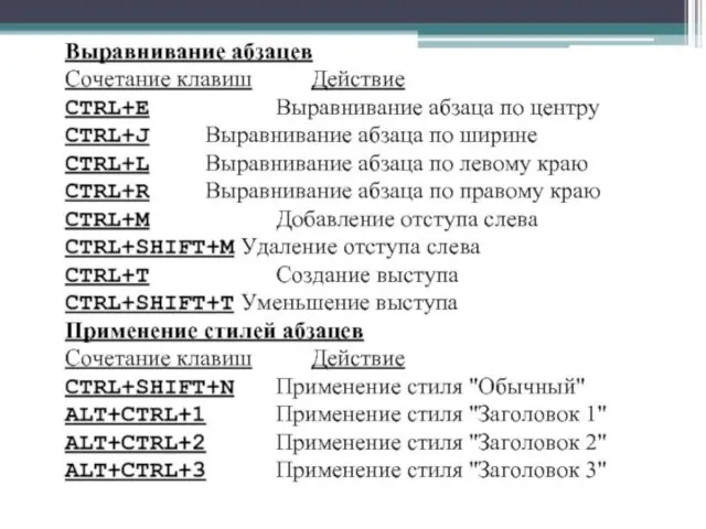 Выравнивание абзацев
 Оплата курсов подготовки водителей
 Использование прикладных компьютерных программ в экологических исследованиях
 Обработка информации
 Архивация данных
 Компьютерные объекты. Файлы и папки
 Программирование на языках высокого уровня. IntelliJ IDEA Community/Ultimate. JDK
 Новый год Wordshop. Задания для квеста
 MATLAB. C++ Builder
 Введение в Python. Лекция 7: Инструкции цикла в Python
 Password Reset
 Система счисления
 Разработка проекта состава и содержание программно-аппаратных мер по обеспечению безопасности информации на объекте
 Teoria de Sistemas e Controlo
 Решение задач на измерение информации (7 класс) (1)
 Работа cam-систем (продолжение). Информационные системы и технологии. Лекция 5
 Условия if/elif/else. Практикум
 Современные инфокоммуникационные услуги и концепция Open system access
 Основы алгоритмизации
 2D графика
 34084031103
 Презентация на тему История вычислительной техники
  Структуры данных
 prezentatsia
 Компьютерные игры
 Практическое задание по анализу данных
 Определение идеи алгоритма, выбор методов решения и структур данных. Деревья