- 01- System Overview Rev A

Содержание
- 2. © 2003, Halliburton Energy Services, Inc. July 2, 2003 LWD System Overview Objectives At the completion
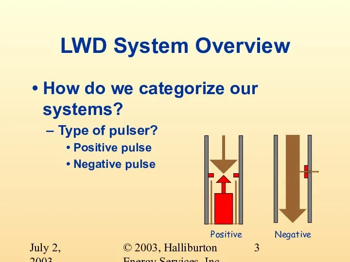
- 3. © 2003, Halliburton Energy Services, Inc. July 2, 2003 LWD System Overview How do we categorize
- 4. © 2003, Halliburton Energy Services, Inc. July 2, 2003 LWD System Overview How do we categorize
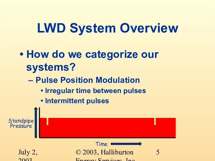
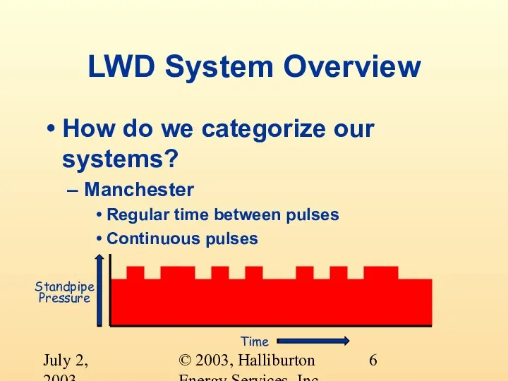
- 5. © 2003, Halliburton Energy Services, Inc. July 2, 2003 LWD System Overview How do we categorize
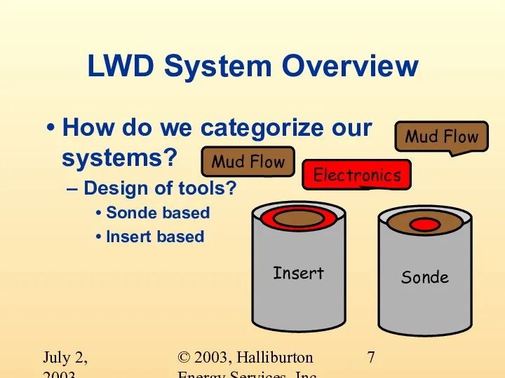
- 6. © 2003, Halliburton Energy Services, Inc. July 2, 2003 LWD System Overview How do we categorize
- 7. © 2003, Halliburton Energy Services, Inc. July 2, 2003 LWD System Overview How do we categorize
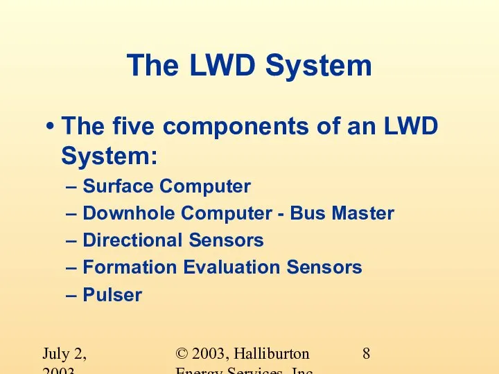
- 8. © 2003, Halliburton Energy Services, Inc. July 2, 2003 The LWD System The five components of
- 9. © 2003, Halliburton Energy Services, Inc. July 2, 2003 Surface Computer INSITE Continuing development Windows NT
- 10. © 2003, Halliburton Energy Services, Inc. July 2, 2003 Surface Computer ISC Development finished DOS based
- 11. © 2003, Halliburton Energy Services, Inc. July 2, 2003 Surface Computer ADAC and Data Handler Development
- 12. © 2003, Halliburton Energy Services, Inc. July 2, 2003 Surface Computer MSC Development finished Unix based
- 13. © 2003, Halliburton Energy Services, Inc. July 2, 2003 Surface Computer PCDWD DOS based Supports Directional
- 14. © 2003, Halliburton Energy Services, Inc. July 2, 2003 Surface Computer MPSR Development finished Introduced in
- 15. © 2003, Halliburton Energy Services, Inc. July 2, 2003 Downhole Computer Bus Master What is a
- 16. © 2003, Halliburton Energy Services, Inc. July 2, 2003 Downhole Computer Bus Master Six current tools
- 17. © 2003, Halliburton Energy Services, Inc. July 2, 2003 Pulsers Negative Pulse Vents mud to the
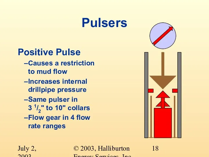
- 18. © 2003, Halliburton Energy Services, Inc. July 2, 2003 Pulsers Positive Pulse Causes a restriction to
- 19. © 2003, Halliburton Energy Services, Inc. July 2, 2003 Directional Sensors Six directional sensors Sonde based
- 20. © 2003, Halliburton Energy Services, Inc. July 2, 2003 Directional Sensors Five directional sensors Sonde Based
- 21. © 2003, Halliburton Energy Services, Inc. July 2, 2003 Formation Evaluation Sensors Sonde Based Gamma GM
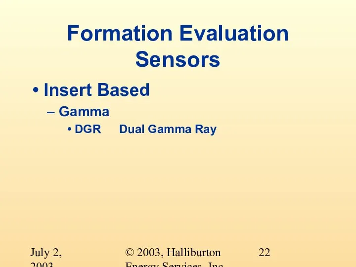
- 22. © 2003, Halliburton Energy Services, Inc. July 2, 2003 Formation Evaluation Sensors Insert Based Gamma DGR
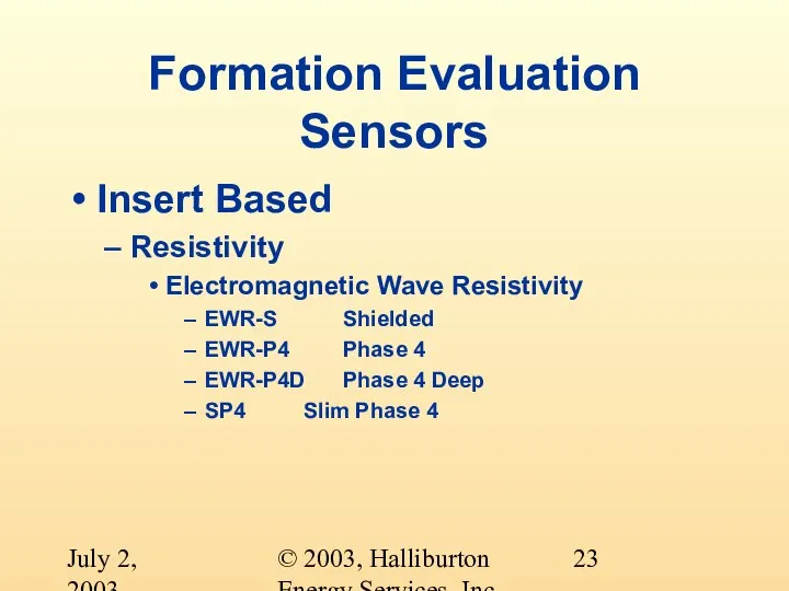
- 23. © 2003, Halliburton Energy Services, Inc. July 2, 2003 Formation Evaluation Sensors Insert Based Resistivity Electromagnetic
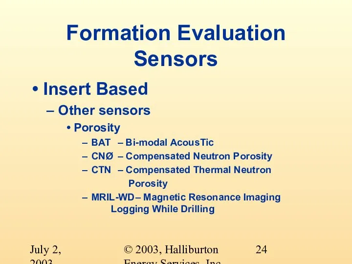
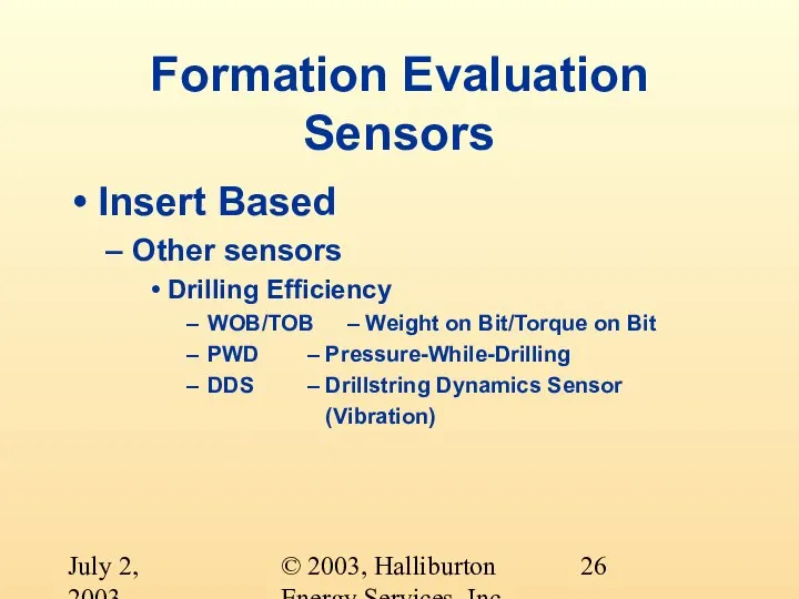
- 24. © 2003, Halliburton Energy Services, Inc. July 2, 2003 Formation Evaluation Sensors Insert Based Other sensors
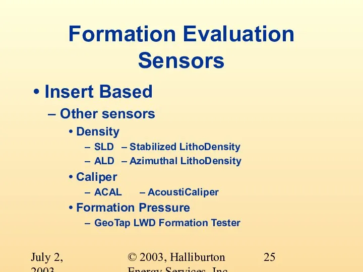
- 25. © 2003, Halliburton Energy Services, Inc. July 2, 2003 Formation Evaluation Sensors Insert Based Other sensors
- 26. © 2003, Halliburton Energy Services, Inc. July 2, 2003 Formation Evaluation Sensors Insert Based Other sensors
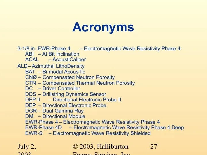
- 27. © 2003, Halliburton Energy Services, Inc. July 2, 2003 Acronyms 3-1/8 in. EWR-Phase 4 – Electromagnetic
- 29. Скачать презентацию
Слайд 3© 2003, Halliburton Energy Services, Inc.
July 2, 2003
LWD System Overview
How do we
© 2003, Halliburton Energy Services, Inc.
July 2, 2003
LWD System Overview
How do we
Слайд 4© 2003, Halliburton Energy Services, Inc.
July 2, 2003
LWD System Overview
How do we
© 2003, Halliburton Energy Services, Inc.
July 2, 2003
LWD System Overview
How do we
Слайд 5© 2003, Halliburton Energy Services, Inc.
July 2, 2003
LWD System Overview
How do we
© 2003, Halliburton Energy Services, Inc.
July 2, 2003
LWD System Overview
How do we
Слайд 6© 2003, Halliburton Energy Services, Inc.
July 2, 2003
LWD System Overview
How do we
© 2003, Halliburton Energy Services, Inc.
July 2, 2003
LWD System Overview
How do we
Слайд 7© 2003, Halliburton Energy Services, Inc.
July 2, 2003
LWD System Overview
How do we
© 2003, Halliburton Energy Services, Inc.
July 2, 2003
LWD System Overview
How do we
Слайд 8© 2003, Halliburton Energy Services, Inc.
July 2, 2003
The LWD System
The five components
© 2003, Halliburton Energy Services, Inc.
July 2, 2003
The LWD System
The five components
Слайд 9© 2003, Halliburton Energy Services, Inc.
July 2, 2003
Surface Computer
INSITE
Continuing development
Windows NT soon
© 2003, Halliburton Energy Services, Inc.
July 2, 2003
Surface Computer
INSITE
Continuing development
Windows NT soon
Слайд 10© 2003, Halliburton Energy Services, Inc.
July 2, 2003
Surface Computer
ISC
Development finished
DOS based
Supports MWD,
© 2003, Halliburton Energy Services, Inc.
July 2, 2003
Surface Computer
ISC
Development finished
DOS based
Supports MWD,
Слайд 11© 2003, Halliburton Energy Services, Inc.
July 2, 2003
Surface Computer
ADAC and Data Handler
Development
© 2003, Halliburton Energy Services, Inc.
July 2, 2003
Surface Computer
ADAC and Data Handler
Development
Слайд 12© 2003, Halliburton Energy Services, Inc.
July 2, 2003
Surface Computer
MSC
Development finished
Unix based
Supports Directional
© 2003, Halliburton Energy Services, Inc.
July 2, 2003
Surface Computer
MSC
Development finished
Unix based
Supports Directional
Слайд 13© 2003, Halliburton Energy Services, Inc.
July 2, 2003
Surface Computer
PCDWD
DOS based
Supports Directional Only
© 2003, Halliburton Energy Services, Inc.
July 2, 2003
Surface Computer
PCDWD
DOS based
Supports Directional Only
Слайд 14© 2003, Halliburton Energy Services, Inc.
July 2, 2003
Surface Computer
MPSR
Development finished
Introduced in Mid
© 2003, Halliburton Energy Services, Inc.
July 2, 2003
Surface Computer
MPSR
Development finished
Introduced in Mid
Слайд 15© 2003, Halliburton Energy Services, Inc.
July 2, 2003
Downhole Computer
Bus Master
What is a
© 2003, Halliburton Energy Services, Inc.
July 2, 2003
Downhole Computer
Bus Master
What is a
Слайд 16© 2003, Halliburton Energy Services, Inc.
July 2, 2003
Downhole Computer
Bus Master
Six current tools
© 2003, Halliburton Energy Services, Inc.
July 2, 2003
Downhole Computer
Bus Master
Six current tools
Слайд 17© 2003, Halliburton Energy Services, Inc.
July 2, 2003
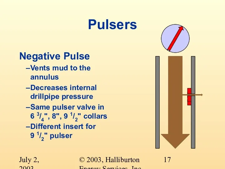
Pulsers
Negative Pulse
Vents mud to the
© 2003, Halliburton Energy Services, Inc.
July 2, 2003
Pulsers
Negative Pulse
Vents mud to the
Слайд 18© 2003, Halliburton Energy Services, Inc.
July 2, 2003
Pulsers
Positive Pulse
Causes a restriction to
© 2003, Halliburton Energy Services, Inc.
July 2, 2003
Pulsers
Positive Pulse
Causes a restriction to
Слайд 19© 2003, Halliburton Energy Services, Inc.
July 2, 2003
Directional Sensors
Six directional sensors
Sonde based
Two
© 2003, Halliburton Energy Services, Inc.
July 2, 2003
Directional Sensors
Six directional sensors
Sonde based
Two
Слайд 20© 2003, Halliburton Energy Services, Inc.
July 2, 2003
Directional Sensors
Five directional sensors
Sonde Based
Three
© 2003, Halliburton Energy Services, Inc.
July 2, 2003
Directional Sensors
Five directional sensors
Sonde Based
Three
Слайд 21© 2003, Halliburton Energy Services, Inc.
July 2, 2003
Formation Evaluation Sensors
Sonde Based
Gamma
GM Gamma Module
PCG Pressure
© 2003, Halliburton Energy Services, Inc.
July 2, 2003
Formation Evaluation Sensors
Sonde Based
Gamma
GM Gamma Module
PCG Pressure
Слайд 22© 2003, Halliburton Energy Services, Inc.
July 2, 2003
Formation Evaluation Sensors
Insert Based
Gamma
DGR Dual Gamma
© 2003, Halliburton Energy Services, Inc.
July 2, 2003
Formation Evaluation Sensors
Insert Based
Gamma
DGR Dual Gamma
Слайд 23© 2003, Halliburton Energy Services, Inc.
July 2, 2003
Formation Evaluation Sensors
Insert Based
Resistivity
Electromagnetic Wave
© 2003, Halliburton Energy Services, Inc.
July 2, 2003
Formation Evaluation Sensors
Insert Based
Resistivity
Electromagnetic Wave
Слайд 24© 2003, Halliburton Energy Services, Inc.
July 2, 2003
Formation Evaluation Sensors
Insert Based
Other sensors
Porosity
BAT –
© 2003, Halliburton Energy Services, Inc.
July 2, 2003
Formation Evaluation Sensors
Insert Based
Other sensors
Porosity
BAT –
Слайд 25© 2003, Halliburton Energy Services, Inc.
July 2, 2003
Formation Evaluation Sensors
Insert Based
Other sensors
Density
SLD –
© 2003, Halliburton Energy Services, Inc.
July 2, 2003
Formation Evaluation Sensors
Insert Based
Other sensors
Density
SLD –
Слайд 26© 2003, Halliburton Energy Services, Inc.
July 2, 2003
Formation Evaluation Sensors
Insert Based
Other sensors
Drilling
© 2003, Halliburton Energy Services, Inc.
July 2, 2003
Formation Evaluation Sensors
Insert Based
Other sensors
Drilling
Слайд 27© 2003, Halliburton Energy Services, Inc.
July 2, 2003
Acronyms
3-1/8 in. EWR-Phase 4 – Electromagnetic
© 2003, Halliburton Energy Services, Inc.
July 2, 2003
Acronyms
3-1/8 in. EWR-Phase 4 – Electromagnetic
 Алгоритм исследования функции с помощью производной
 Музафер Шериф
 Труд- основа жизни 6 класс
 Исследовательский проект:«Измерение длины предметов»
 Применение теории игр в политике и экономике
 Саласпилс
 Действия Федеральной антимонопольной службы
 Презентация на тему Март – первый весенний месяц
  структура
 Общеобразовательная организация, учебный центр Наука-Сервис
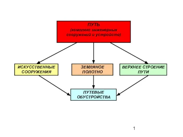 ЗЕМЛЯНОЕ ПОЛОТНО
 ЭТИКЕТ за праздничным столом
 Правовой фундамент государства. 12 декабря – День Конституции
 Конвенция ООН о правах ребёнка
 Моя Мадонна
 Урок математики с Машей и Мишей
 Петербург-герой романов Достоевского
 Презентация на тему "Жизнь и творчество" 11 класс
 "Петербургские повести" Н.В. Гоголя
 7 мифов о Чернобыле
 Управленческий учёт и учёт персонала
 Природные зоны Зона степей
 Шоколад
 Технология повышения урожая овощей
 Планета - Сатурн
 Специальное предложение по контейнерным закупкам
 Игра, как метод подачи информации
 BUSINESS PROCESS