- Fuel Handling Systems Licensing Documentation

Содержание
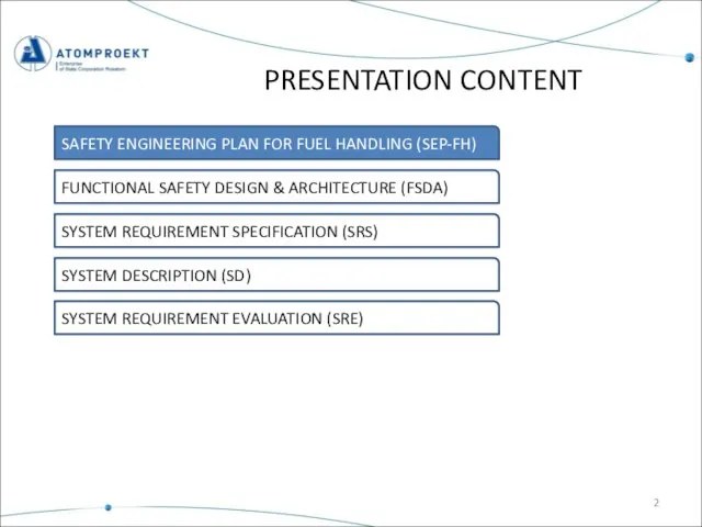
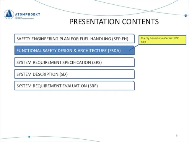
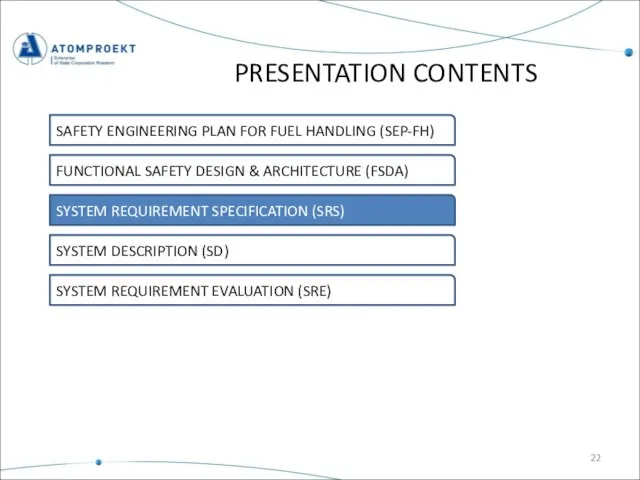
- 2. PRESENTATION CONTENT SAFETY ENGINEERING PLAN FOR FUEL HANDLING (SEP-FH) FUNCTIONAL SAFETY DESIGN & ARCHITECTURE (FSDA) SYSTEM
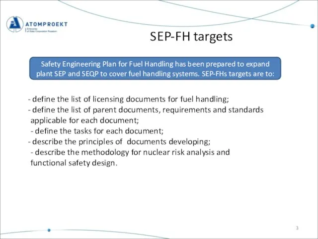
- 3. SEP-FH targets Safety Engineering Plan for Fuel Handling has been prepared to expand plant SEP and
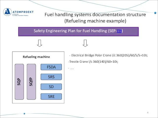
- 4. Fuel handling systems documentation structure (Refueling machine example) Safety Engineering Plan for Fuel Handling (SEP-FH) SQfP
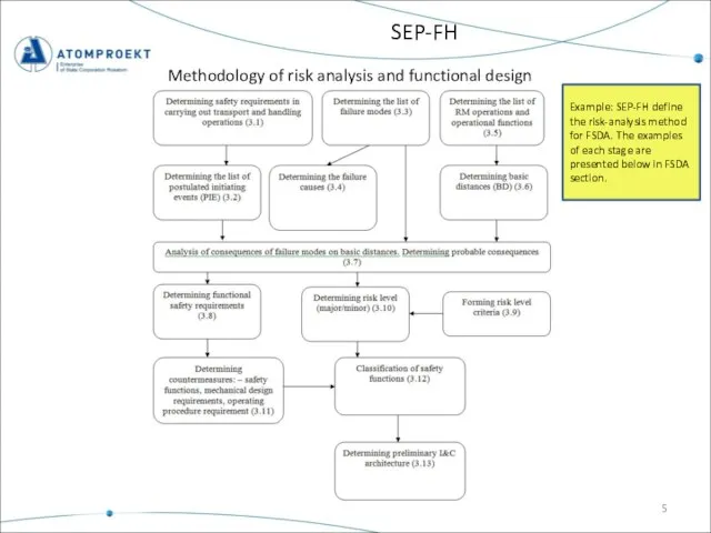
- 5. SEP-FH Methodology of risk analysis and functional design Example: SEP-FH define the risk-analysis method for FSDA.
- 6. PRESENTATION CONTENTS SAFETY ENGINEERING PLAN FOR FUEL HANDLING (SEP-FH) FUNCTIONAL SAFETY DESIGN & ARCHITECTURE (FSDA) SYSTEM
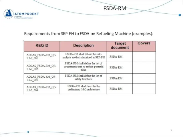
- 7. Requirements from SEP-FH to FSDA on Refueling Machine (examples): FSDA-RM
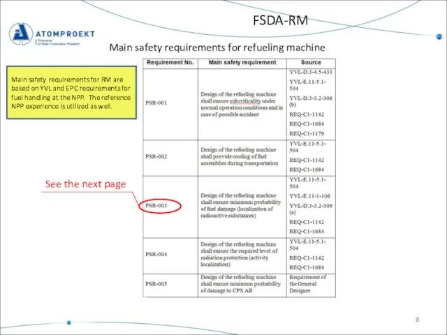
- 8. FSDA-RM Main safety requirements for refueling machine See the next page Main safety requirements for RM
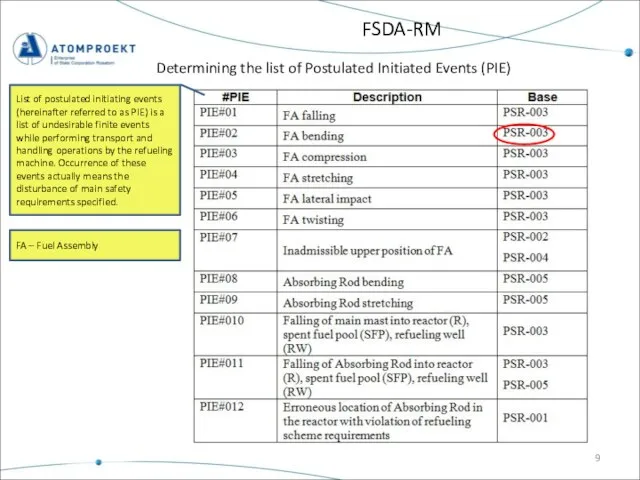
- 9. FSDA-RM Determining the list of Postulated Initiated Events (PIE) List of postulated initiating events (hereinafter referred
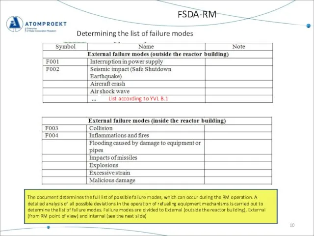
- 10. FSDA-RM Determining the list of failure modes List according to YVL B.1 The document determines the
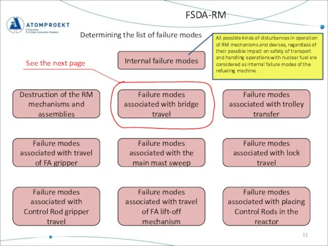
- 11. FSDA-RM Determining the list of failure modes Internal failure modes Destruction of the RM mechanisms and
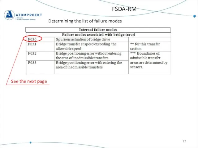
- 12. FSDA-RM Determining the list of failure modes See the next page
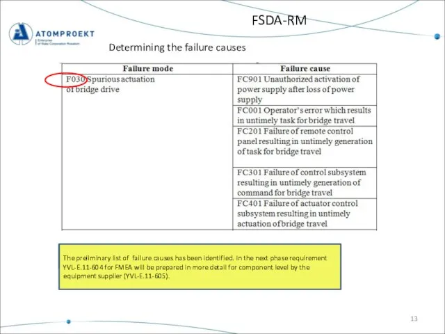
- 13. FSDA-RM Determining the failure causes The preliminary list of failure causes has been identified. In the
- 14. Moving direction FSDA-RM Determining basic distances Basic distances Horizontal Vertical Rotation RM location Reactor, Fuel Pool,
- 15. FSDA-RM Determining basic distances Basic distances in case of horizontal movements of RM BD 10 –
- 16. FSDA-RM Determining basic distances Basic distances in case of vertical movements for the FA transfer operations.
- 17. FSDA-RM Analysis of failure mode consequence on basic interval. Identification of safety requirements Basic distance (BD-01)
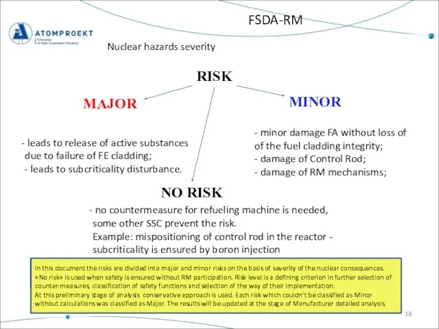
- 18. FSDA-RM Nuclear hazards severity RISK MAJOR MINOR leads to release of active substances due to failure
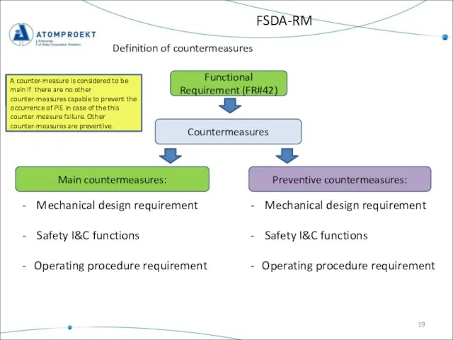
- 19. FSDA-RM Definition of countermeasures Functional Requirement (FR#42) Countermeasures Main countermeasures: Preventive countermeasures: Mechanical design requirement Safety
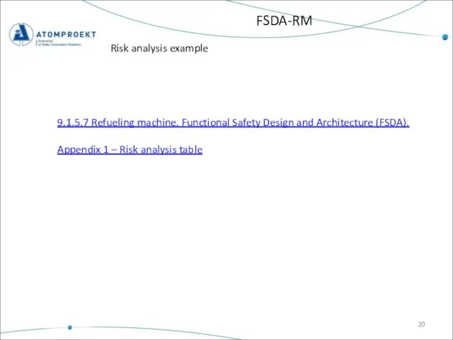
- 20. FSDA-RM Risk analysis example 9.1.5.7 Refueling machine. Functional Safety Design and Architecture (FSDA). Appendix 1 –
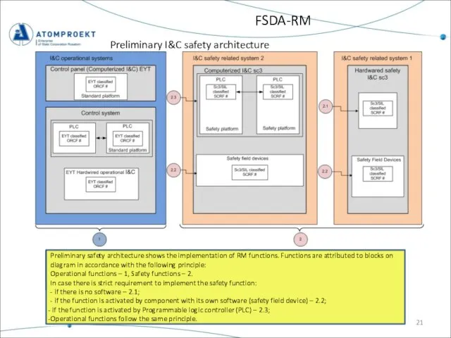
- 21. FSDA-RM Preliminary I&C safety architecture Preliminary safety architecture shows the implementation of RM functions. Functions are
- 22. PRESENTATION CONTENTS SAFETY ENGINEERING PLAN FOR FUEL HANDLING (SEP-FH) FUNCTIONAL SAFETY DESIGN & ARCHITECTURE (FSDA) SYSTEM
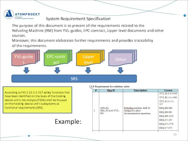
- 23. System Requirement Specification The purpose of this document is to present all the requirements related to
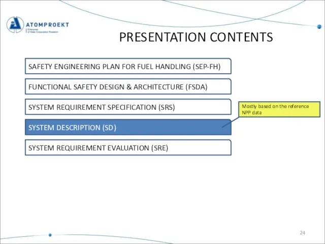
- 24. PRESENTATION CONTENTS SAFETY ENGINEERING PLAN FOR FUEL HANDLING (SEP-FH) FUNCTIONAL SAFETY DESIGN & ARCHITECTURE (FSDA) SYSTEM
- 25. System description Contents 9.1.5 Transportation and Handling Equipment of the Fuel Handling System 9.1.5.7. REFUELING MACHINE
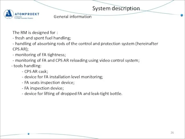
- 26. System description The RM is designed for : - fresh and spent fuel handling; - handling
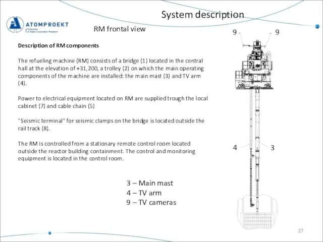
- 27. System description 3 – Main mast 4 – TV arm 9 – TV cameras Description of
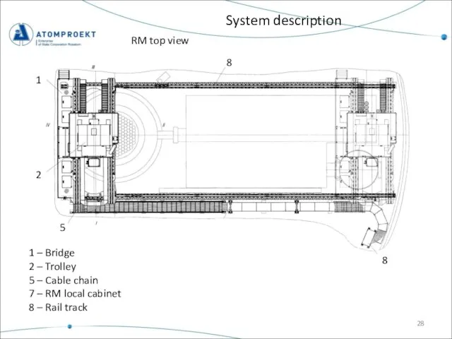
- 28. System description 1 – Bridge 2 – Trolley 5 – Cable chain 7 – RM local
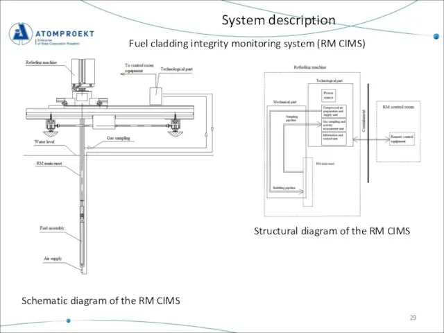
- 29. System description Fuel cladding integrity monitoring system (RM CIMS) Schematic diagram of the RM CIMS Structural
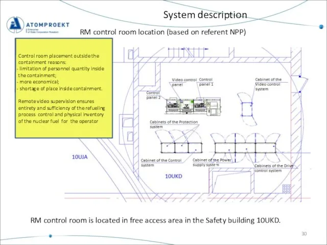
- 30. System description RM control room is located in free access area in the Safety building 10UKD.
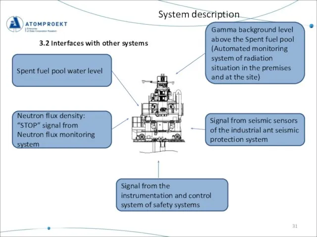
- 31. System description 3.2 Interfaces with other systems Gamma background level above the Spent fuel pool (Automated
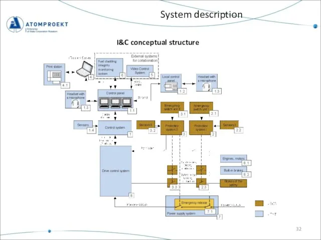
- 32. System description I&C conceptual structure
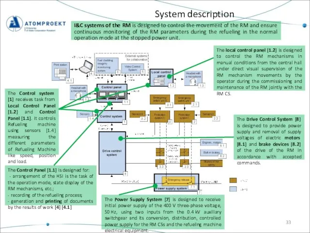
- 33. System description I&C systems of the RM is designed to control the movement of the RM
- 34. System description The protection system I [2] is designed to perform the protection and interlock function,
- 35. Composition of RM systems with preliminary safety classification. RM systems are composed of the following components
- 36. System description RMCS purposes Control purpose Protection and interlock purpose Diagnostic purpose Information purpose 3.6.2 RMCS
- 37. System description RMCS control conditions on on on on Partly off
- 38. Free movement area boundary System description Permissible horizontal movement area of RM mechanisms Free movement area
- 39. PRESENTATION CONTENTS SAFETY ENGINEERING PLAN FOR FUEL HANDLING (SEP-FH) FUNCTIONAL SAFETY DESIGN & ARCHITECTURE (FSDA) SYSTEM
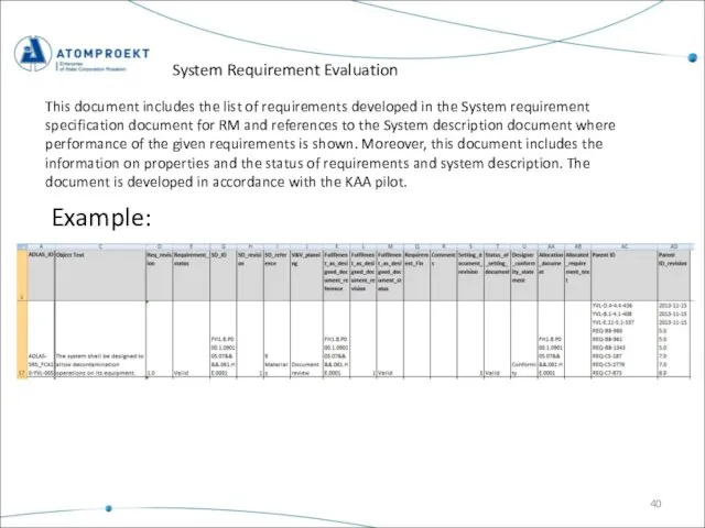
- 40. System Requirement Evaluation Example: This document includes the list of requirements developed in the System requirement
- 41. Thank you for your attention! Thank you for attention
- 42. Thank you for your attention! Thank you for attention
- 44. Скачать презентацию
Слайд 2PRESENTATION CONTENT
SAFETY ENGINEERING PLAN FOR FUEL HANDLING (SEP-FH)
FUNCTIONAL SAFETY DESIGN & ARCHITECTURE
PRESENTATION CONTENT
SAFETY ENGINEERING PLAN FOR FUEL HANDLING (SEP-FH)
FUNCTIONAL SAFETY DESIGN & ARCHITECTURE
Слайд 3SEP-FH targets
Safety Engineering Plan for Fuel Handling has been prepared to expand
SEP-FH targets
Safety Engineering Plan for Fuel Handling has been prepared to expand
Слайд 4Fuel handling systems documentation structure
(Refueling machine example)
Safety Engineering Plan for Fuel Handling
Fuel handling systems documentation structure
(Refueling machine example)
Safety Engineering Plan for Fuel Handling
Слайд 5SEP-FH
Methodology of risk analysis and functional design
Example: SEP-FH define the risk-analysis
SEP-FH
Methodology of risk analysis and functional design
Example: SEP-FH define the risk-analysis
Слайд 6PRESENTATION CONTENTS
SAFETY ENGINEERING PLAN FOR FUEL HANDLING (SEP-FH)
FUNCTIONAL SAFETY DESIGN & ARCHITECTURE
PRESENTATION CONTENTS
SAFETY ENGINEERING PLAN FOR FUEL HANDLING (SEP-FH)
FUNCTIONAL SAFETY DESIGN & ARCHITECTURE
Слайд 7Requirements from SEP-FH to FSDA on Refueling Machine (examples):
FSDA-RM
Requirements from SEP-FH to FSDA on Refueling Machine (examples):
FSDA-RM
Слайд 8FSDA-RM
Main safety requirements for refueling machine
See the next page
Main safety requirements for
FSDA-RM
Main safety requirements for refueling machine
See the next page
Main safety requirements for
Слайд 9FSDA-RM
Determining the list of Postulated Initiated Events (PIE)
List of postulated initiating events
FSDA-RM
Determining the list of Postulated Initiated Events (PIE)
List of postulated initiating events
Слайд 10FSDA-RM
Determining the list of failure modes
List according to YVL B.1
The document determines
FSDA-RM
Determining the list of failure modes
List according to YVL B.1
The document determines
Слайд 11FSDA-RM
Determining the list of failure modes
Internal failure modes
Destruction of the RM mechanisms
FSDA-RM
Determining the list of failure modes
Internal failure modes
Destruction of the RM mechanisms
Слайд 12FSDA-RM
Determining the list of failure modes
See the next page
FSDA-RM
Determining the list of failure modes
See the next page
Слайд 13FSDA-RM
Determining the failure causes
The preliminary list of failure causes has been identified.
FSDA-RM
Determining the failure causes
The preliminary list of failure causes has been identified.
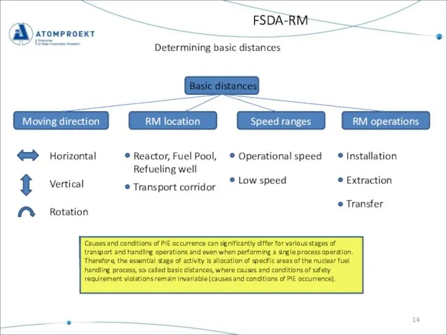
Слайд 14Moving direction
FSDA-RM
Determining basic distances
Basic distances
Horizontal
Vertical
Rotation
RM location
Reactor, Fuel Pool,
Refueling well
Transport corridor
RM operations
Speed
Moving direction
FSDA-RM
Determining basic distances
Basic distances
Horizontal
Vertical
Rotation
RM location
Reactor, Fuel Pool,
Refueling well
Transport corridor
RM operations
Speed
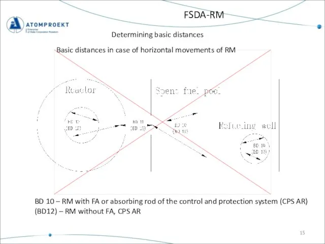
Слайд 15FSDA-RM
Determining basic distances
Basic distances in case of horizontal movements of RM
BD 10
FSDA-RM
Determining basic distances
Basic distances in case of horizontal movements of RM
BD 10
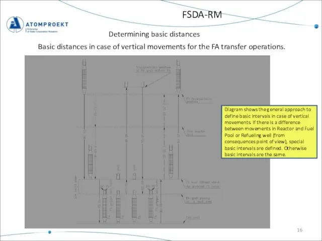
Слайд 16FSDA-RM
Determining basic distances
Basic distances in case of vertical movements for the FA
FSDA-RM
Determining basic distances
Basic distances in case of vertical movements for the FA
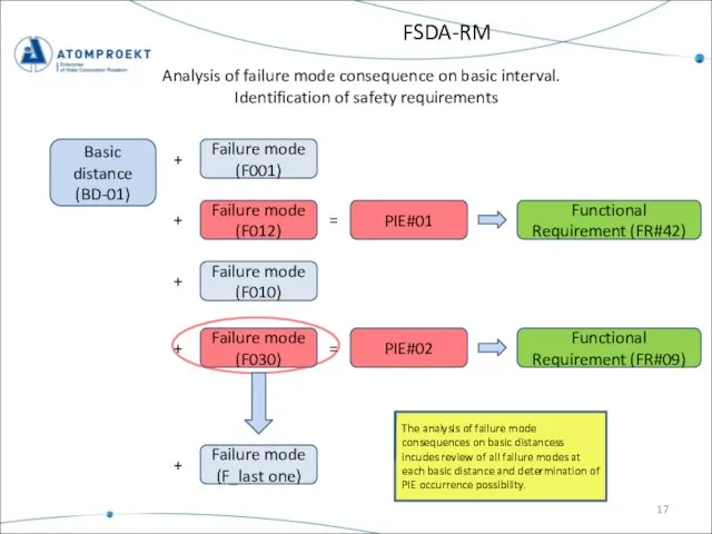
Слайд 17FSDA-RM
Analysis of failure mode consequence on basic interval.
Identification of safety requirements
Basic
FSDA-RM
Analysis of failure mode consequence on basic interval.
Identification of safety requirements
Basic
Слайд 18FSDA-RM
Nuclear hazards severity
RISK
MAJOR
MINOR
leads to release of active substances
due to failure
FSDA-RM
Nuclear hazards severity
RISK
MAJOR
MINOR
leads to release of active substances
due to failure
Слайд 19FSDA-RM
Definition of countermeasures
Functional Requirement (FR#42)
Countermeasures
Main countermeasures:
Preventive countermeasures:
Mechanical design requirement
Safety I&C functions
Operating
FSDA-RM
Definition of countermeasures
Functional Requirement (FR#42)
Countermeasures
Main countermeasures:
Preventive countermeasures:
Mechanical design requirement
Safety I&C functions
Operating
Слайд 20FSDA-RM
Risk analysis example
9.1.5.7 Refueling machine. Functional Safety Design and Architecture (FSDA).
Appendix 1
FSDA-RM
Risk analysis example
9.1.5.7 Refueling machine. Functional Safety Design and Architecture (FSDA).
Appendix 1
Слайд 21FSDA-RM
Preliminary I&C safety architecture
Preliminary safety architecture shows the implementation of RM
FSDA-RM
Preliminary I&C safety architecture
Preliminary safety architecture shows the implementation of RM
Слайд 22PRESENTATION CONTENTS
SAFETY ENGINEERING PLAN FOR FUEL HANDLING (SEP-FH)
FUNCTIONAL SAFETY DESIGN & ARCHITECTURE
PRESENTATION CONTENTS
SAFETY ENGINEERING PLAN FOR FUEL HANDLING (SEP-FH)
FUNCTIONAL SAFETY DESIGN & ARCHITECTURE
Слайд 23System Requirement Specification
The purpose of this document is to present all the
System Requirement Specification
The purpose of this document is to present all the
Слайд 24PRESENTATION CONTENTS
SAFETY ENGINEERING PLAN FOR FUEL HANDLING (SEP-FH)
FUNCTIONAL SAFETY DESIGN & ARCHITECTURE
PRESENTATION CONTENTS
SAFETY ENGINEERING PLAN FOR FUEL HANDLING (SEP-FH)
FUNCTIONAL SAFETY DESIGN & ARCHITECTURE
Слайд 25System description
Contents
9.1.5 Transportation and Handling Equipment of the Fuel Handling System
9.1.5.7.
System description
Contents
9.1.5 Transportation and Handling Equipment of the Fuel Handling System
9.1.5.7.
Слайд 26System description
The RM is designed for :
- fresh and spent fuel handling;
- handling
System description
The RM is designed for :
- fresh and spent fuel handling;
- handling
Слайд 27System description
3 – Main mast
4 – TV arm
9 – TV cameras
Description of
System description
3 – Main mast
4 – TV arm
9 – TV cameras
Description of
Слайд 28System description
1 – Bridge
2 – Trolley
5 – Cable chain
7 – RM local
System description
1 – Bridge
2 – Trolley
5 – Cable chain
7 – RM local
Слайд 29System description
Fuel cladding integrity monitoring system (RM CIMS)
Schematic diagram of the RM
System description
Fuel cladding integrity monitoring system (RM CIMS)
Schematic diagram of the RM
Слайд 30System description
RM control room is located in free access area in the
System description
RM control room is located in free access area in the
Слайд 31System description
3.2 Interfaces with other systems
Gamma background level
above the Spent fuel
System description
3.2 Interfaces with other systems
Gamma background level
above the Spent fuel
Слайд 32System description
I&C conceptual structure
System description
I&C conceptual structure
Слайд 33System description
I&C systems of the RM is designed to control the movement
System description
I&C systems of the RM is designed to control the movement
Слайд 34System description
The protection system I [2] is designed to perform the protection
System description
The protection system I [2] is designed to perform the protection
![System description The protection system I [2] is designed to perform the](/_ipx/f_webp&q_80&fit_contain&s_1440x1080/imagesDir/jpg/855024/slide-33.jpg)
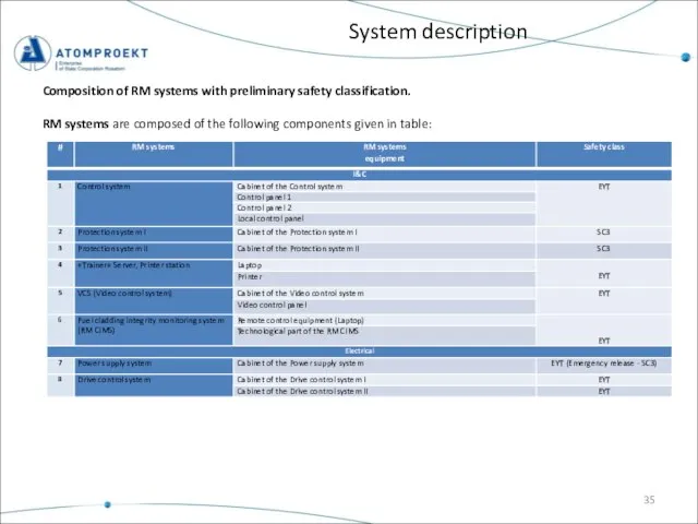
Слайд 35Composition of RM systems with preliminary safety classification.
RM systems are composed of
Composition of RM systems with preliminary safety classification.
RM systems are composed of
Слайд 36System description
RMCS purposes
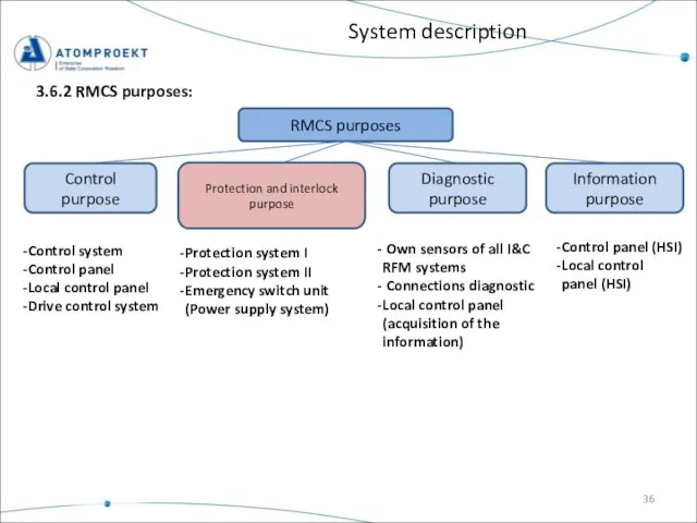
Control purpose
Protection and interlock purpose
Diagnostic purpose
Information purpose
3.6.2 RMCS purposes:
Control system
Control
System description
RMCS purposes
Control purpose
Protection and interlock purpose
Diagnostic purpose
Information purpose
3.6.2 RMCS purposes:
Control system
Control
Слайд 37System description
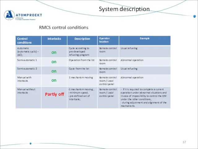
RMCS control conditions
on
on
on
on
Partly off
System description
RMCS control conditions
on
on
on
on
Partly off
Слайд 38Free
movement
area boundary
System description
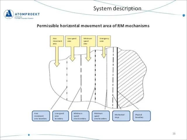
Permissible horizontal movement area of RM mechanisms
Free
Free
movement
area boundary
System description
Permissible horizontal movement area of RM mechanisms
Free
Слайд 39PRESENTATION CONTENTS
SAFETY ENGINEERING PLAN FOR FUEL HANDLING (SEP-FH)
FUNCTIONAL SAFETY DESIGN & ARCHITECTURE
PRESENTATION CONTENTS
SAFETY ENGINEERING PLAN FOR FUEL HANDLING (SEP-FH)
FUNCTIONAL SAFETY DESIGN & ARCHITECTURE
Слайд 40System Requirement Evaluation
Example:
This document includes the list of requirements developed in the
System Requirement Evaluation
Example:
This document includes the list of requirements developed in the
Слайд 41Thank you for your attention!
Thank you for attention
Thank you for your attention!
Thank you for attention
Слайд 42Thank you for your attention!
Thank you for attention
Thank you for your attention!
Thank you for attention

 апапр
апапр Реализация ФГОС в работе школьной библиотеки. Воспитание культурного и гражданского самосознания учащихся.
 Гандбол - в школу
 Welcome to Russia
  Скиния
 Как правильно выбрать мультимедийный проектор
 Феодальная раздробленность на Руси 6 класс
 Презентация на тему Виды и типы корней
 Банки, терминалы, интернет – ресурсы, Карта номер один.
 Простановка размеров на чертеже (ГОСТ 2.307-2011)
 «Осветительное оборудование»
 Федеральный государственный образовательный стандарт – новая идеология образования
 ПРЕЗЕНТАЦИЯ ПО ИСТОРИИ
 Закрепление изученного
 2
2 WATCH TV WALK PLAY FOOT BALL LISTEN TO
 Подготовка к изложению - описанию метели (по повести А.С. Пушкина "Метель")
 Системная среда Windows
 Планирование и осуществление мероприятий по управлению финансовыми ресурсами организации на примере ООО АСТРОНГ
 Лингвистические основы вариативности перевода английских конструкций Complex Object на русский язык
 Коммунальная инфраструктура
 Реализация и применение норм права
 Презентация на тему Хищные птицы
  КОРРОЗИЯ МЕТАЛЛОВ
 Заболевания пищеварительной системы
 Август Фердинанд Мёбиус
 Докладчик – В.В. Колодченко Информация об освоении средств дорожного фонда за I полугодие 2012 года
 Филевский парк. Сеславинская ул. Документация по благоустройству дворовых территорий