- LAM2 JTAG Connection. For Cheetah 4/5

Содержание
- 2. HW Setup Setup will require: Digilent HS1 JTAG dongle 1x6 male to male 2.54mm pitch header
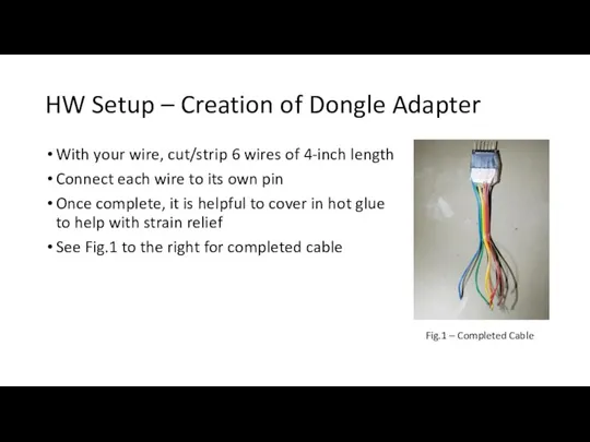
- 3. HW Setup – Creation of Dongle Adapter With your wire, cut/strip 6 wires of 4-inch length
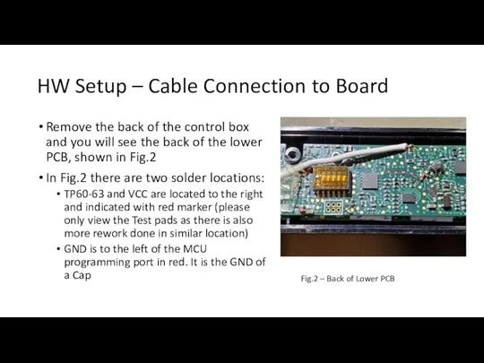
- 4. HW Setup – Cable Connection to Board Remove the back of the control box and you
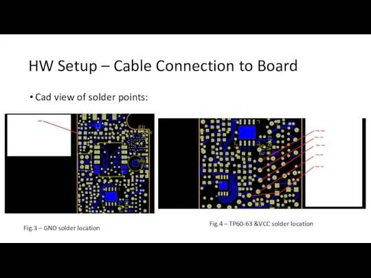
- 5. HW Setup – Cable Connection to Board Cad view of solder points: Fig.3 – GND solder
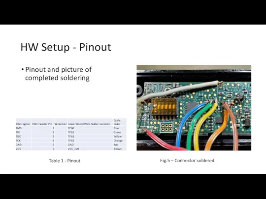
- 6. HW Setup - Pinout Pinout and picture of completed soldering Table 1 - Pinout Fig.5 –
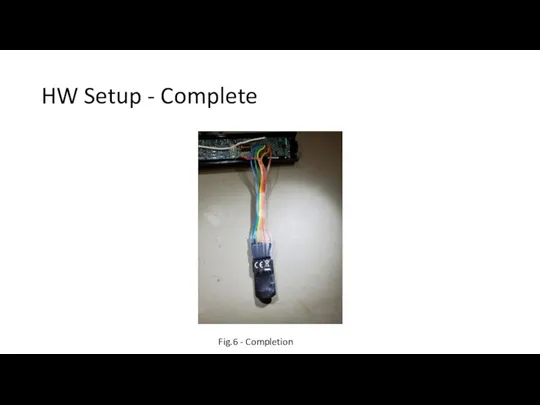
- 7. HW Setup - Complete Fig.6 - Completion
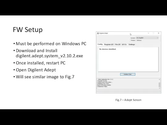
- 8. FW Setup Must be performed on Windows PC Download and Install digilent.adept.system_v2.10.2.exe Once installed, restart PC
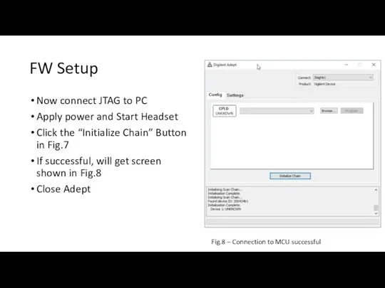
- 9. FW Setup Now connect JTAG to PC Apply power and Start Headset Click the “Initialize Chain”
- 11. Скачать презентацию
Слайд 3HW Setup – Creation of Dongle Adapter
With your wire, cut/strip 6 wires
HW Setup – Creation of Dongle Adapter
With your wire, cut/strip 6 wires
Слайд 4HW Setup – Cable Connection to Board
Remove the back of the control
HW Setup – Cable Connection to Board
Remove the back of the control
Слайд 5HW Setup – Cable Connection to Board
Cad view of solder points:
Fig.3 –
HW Setup – Cable Connection to Board
Cad view of solder points:
Fig.3 –
Слайд 6HW Setup - Pinout
Pinout and picture of completed soldering
Table 1 - Pinout
Fig.5
HW Setup - Pinout
Pinout and picture of completed soldering
Table 1 - Pinout
Fig.5
Слайд 7HW Setup - Complete
Fig.6 - Completion
HW Setup - Complete
Fig.6 - Completion
Слайд 8FW Setup
Must be performed on Windows PC
Download and Install digilent.adept.system_v2.10.2.exe
Once installed, restart
FW Setup
Must be performed on Windows PC
Download and Install digilent.adept.system_v2.10.2.exe
Once installed, restart
Слайд 9FW Setup
Now connect JTAG to PC
Apply power and Start Headset
Click the “Initialize
FW Setup
Now connect JTAG to PC
Apply power and Start Headset
Click the “Initialize
 ВКР: Организация производства и разработка технологии получения поковок штампованных тяга шасси
 Использование национально-регионального компонента в обучении химии на элективных курсах
 Презентация на тему Гора самоцветов
 RUS-01 Compensation plan Wantage One 2.4 Euro
 Лжедмитрий I (1605 – 1606)
 НАЦИИ И МЕЖНАЦИОНАЛЬНЫЕ ОТНОШЕНИЯ.
 Готовность учителя начальных классов к реализации стандарта нового поколения
 Разные люди живут на планете, но…К ДОКТОРУ ХОДЯТ ВСЕ ЛЮДИ НА СВЕТЕ!
 Велесов день - середина зимы. Фольклорное путешествие
 Развитие сплоченности
 Правовые традиции в Карибском регионе: плюсы и минусы для компаративиста
 Как построить успешную карьеру программисту
 Час общения Твой новый друг
 Где логика. Найди общее
 ИНВЕСТИЦИОННЫЕ ФОНДЫДОСТОЙНАЯ АЛЬТЕРНАТИВА ТРАДИЦИОННЫМ ФИНАНСОВЫМ ИНСТРУМЕНТАМ
 Поздравление с Новым годом
 Презентация на тему РАВНОМЕРНОЕ ДВИЖЕНИЕ Механическое движение:перемещение,скорость,ускорение
  Русские народные праздники
 ОАО НПО «Наука» Годовой отчет за 2007 год
 Паркинсонизм и болезнь Паркинсона
  Расход воды человеком
 Презентация на тему Признаки параллельности прямых
 Мартен Ван Северен
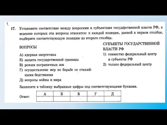 Политическая система. Субъекты государственной власти РФ
 Widening The Net: Improving Access To IT Services And The Internet In Russia
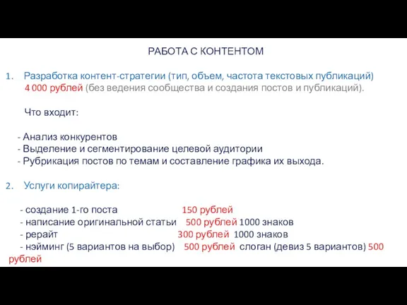 Работа с контентом
 Решение задач на сравнение
 Рационально-эмотивно-поведенческая терапия как часть семейства КБТ