- Описание двигателя

Содержание
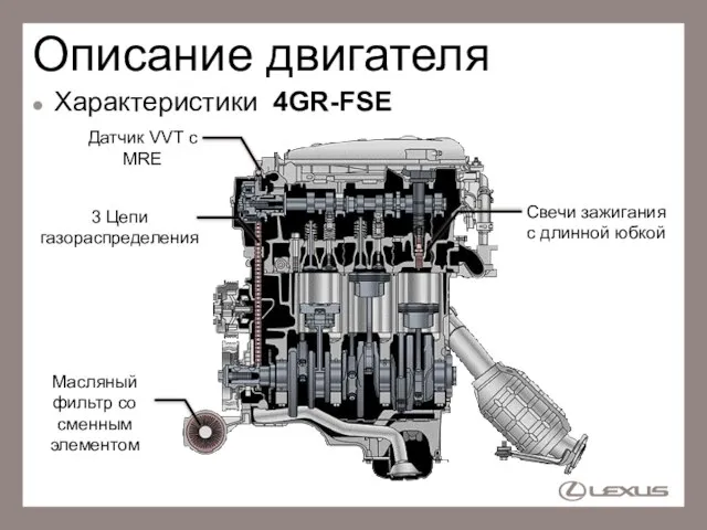
- 2. Описание двигателя Характеристики 4GR-FSE 3 Цепи газораспределения Свечи зажигания с длинной юбкой Масляный фильтр со сменным
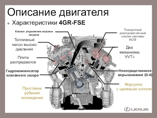
- 3. Описание двигателя Характеристики 4GR-FSE Два механизма VVT-i Проставка рубашки охлаждения Гидрокомпенсатор клапанного зазора Поворотный электромагнитный клапан
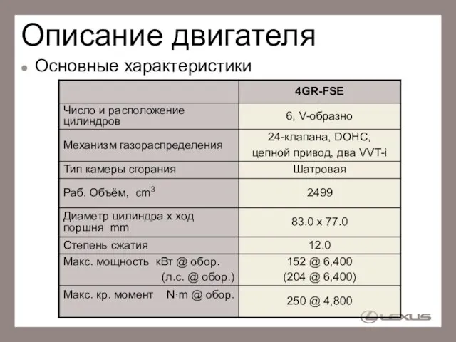
- 4. Описание двигателя Основные характеристики
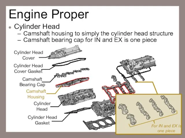
- 5. Engine Proper Cylinder Head Camshaft housing to simply the cylinder head structure Camshaft bearing cap for
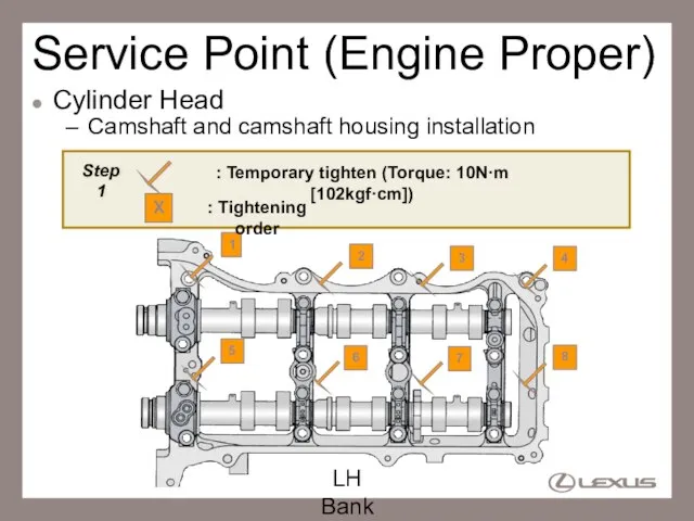
- 6. Service Point (Engine Proper) Cylinder Head Camshaft and camshaft housing installation LH Bank Step1 : Temporary
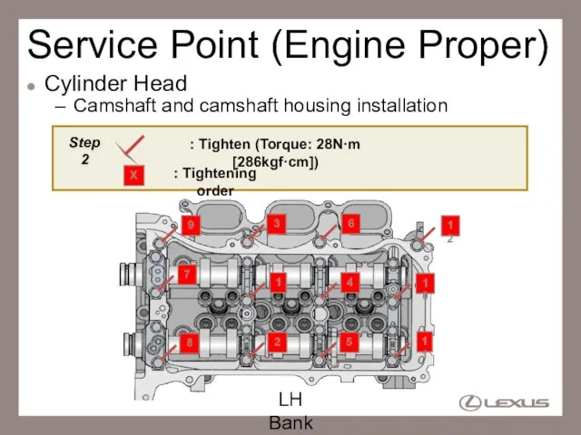
- 7. Service Point (Engine Proper) Cylinder Head Camshaft and camshaft housing installation LH Bank Step2 : Tighten
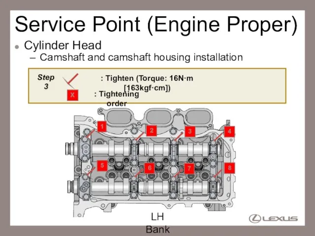
- 8. Service Point (Engine Proper) Cylinder Head Camshaft and camshaft housing installation LH Bank Step3 : Tighten
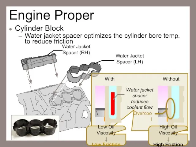
- 9. Engine Proper Cylinder Block Water jacket spacer optimizes the cylinder bore temp. to reduce friction Water
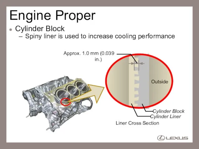
- 10. Engine Proper Cylinder Block Spiny liner is used to increase cooling performance Approx. 1.0 mm (0.039
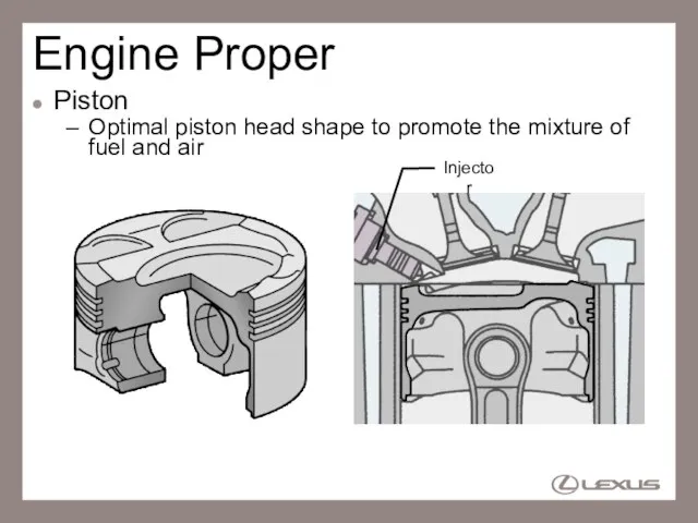
- 11. Engine Proper Piston Optimal piston head shape to promote the mixture of fuel and air Injector
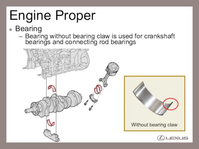
- 12. Engine Proper Bearing Bearing without bearing claw is used for crankshaft bearings and connecting rod bearings
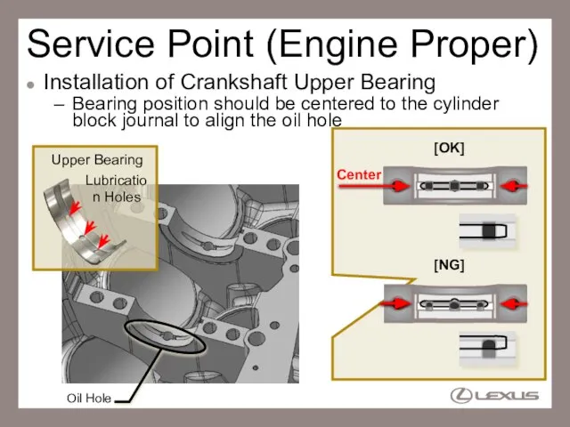
- 13. Service Point (Engine Proper) Installation of Crankshaft Upper Bearing Bearing position should be centered to the
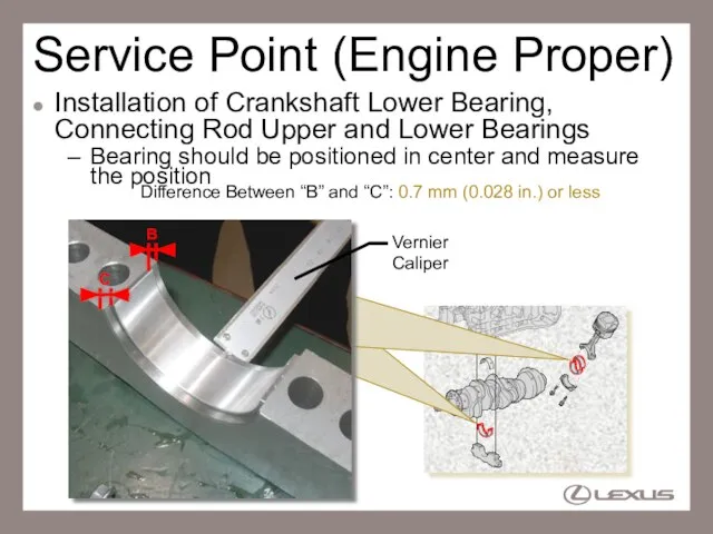
- 14. Service Point (Engine Proper) Installation of Crankshaft Lower Bearing, Connecting Rod Upper and Lower Bearings Bearing
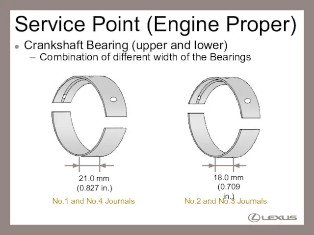
- 15. Service Point (Engine Proper) Crankshaft Bearing (upper and lower) Combination of different width of the Bearings
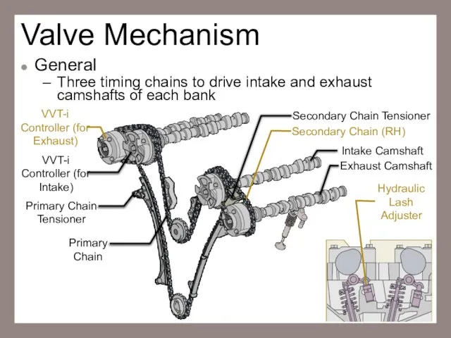
- 16. Valve Mechanism General Three timing chains to drive intake and exhaust camshafts of each bank Intake
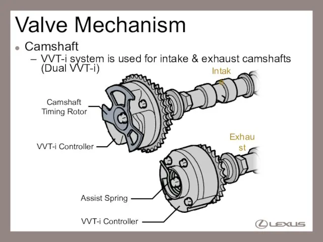
- 17. Valve Mechanism Camshaft VVT-i system is used for intake & exhaust camshafts (Dual VVT-i) VVT-i Controller
- 18. Valve Mechanism Camshaft RH bank exhaust camshaft is provided with the cam to drive the high-pressure
- 19. Valve Mechanism Timing Chain Three timing chains to drive intake and exhaust camshafts of each bank
- 20. Valve Mechanism Chain Tensioner Primary chain tensioner Ratchet type non-return mechanism Service hall for remove and
- 21. Valve Mechanism Chain Tensioner 2 secondary chain tensioners are used for left and right bank Left
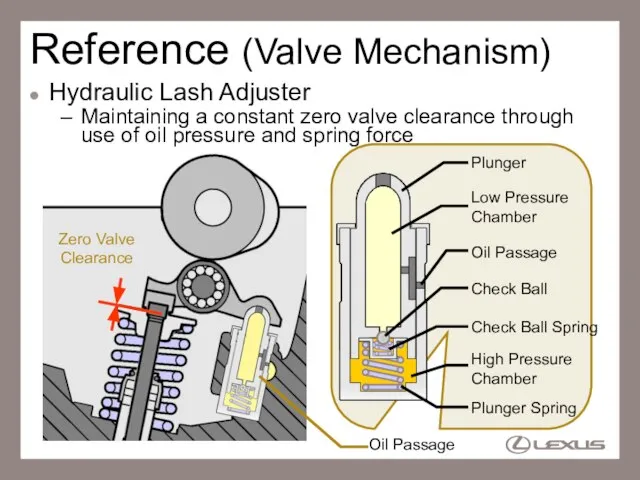
- 22. Reference (Valve Mechanism) Hydraulic Lash Adjuster Maintaining a constant zero valve clearance through use of oil
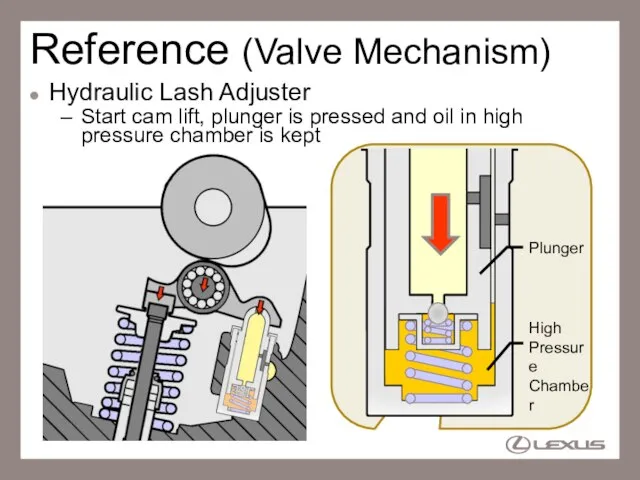
- 23. Reference (Valve Mechanism) Hydraulic Lash Adjuster Start cam lift, plunger is pressed and oil in high
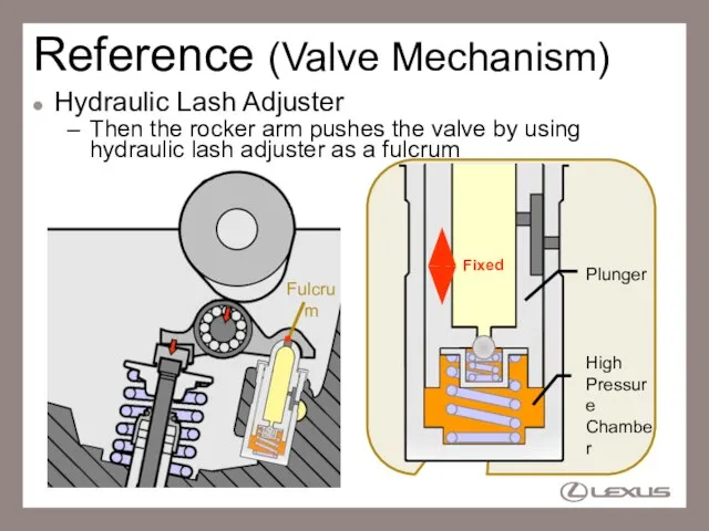
- 24. Reference (Valve Mechanism) Hydraulic Lash Adjuster Then the rocker arm pushes the valve by using hydraulic
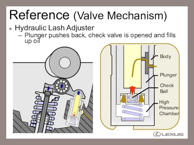
- 25. Reference (Valve Mechanism) Hydraulic Lash Adjuster Plunger pushes back, check valve is opened and fills up
- 26. Zero Valve Clearance Reference (Valve Mechanism) Hydraulic Lash Adjuster Plunger is pushed up, then, valve clearance
- 27. Reference (Valve Mechanism) Hydraulic Lash Adjuster Operation
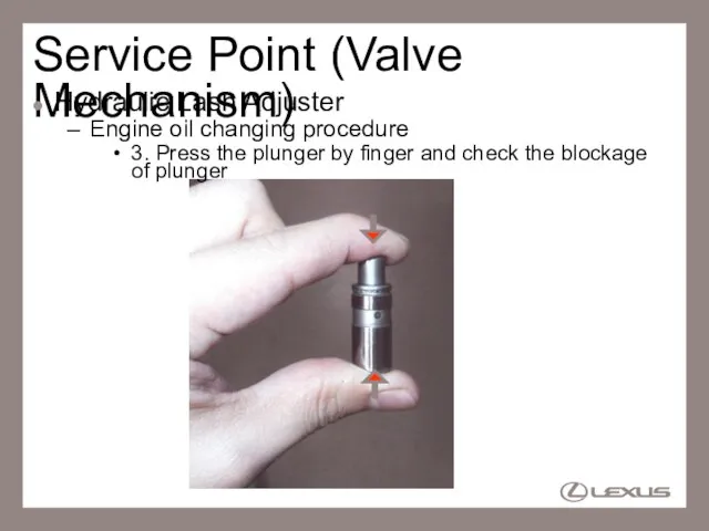
- 28. Service Point (Valve Mechanism) Hydraulic Lash Adjuster Engine oil changing procedure 1. Pushing check ball down
- 29. Service Point (Valve Mechanism) Hydraulic Lash Adjuster Engine oil changing procedure 2. Immerse hydraulic lash adjuster
- 30. Service Point (Valve Mechanism) Hydraulic Lash Adjuster Engine oil changing procedure 3. Press the plunger by
- 31. Service Point (Valve Mechanism) Hydraulic Lash Adjuster Engine oil changing procedure If plunger is compressed after
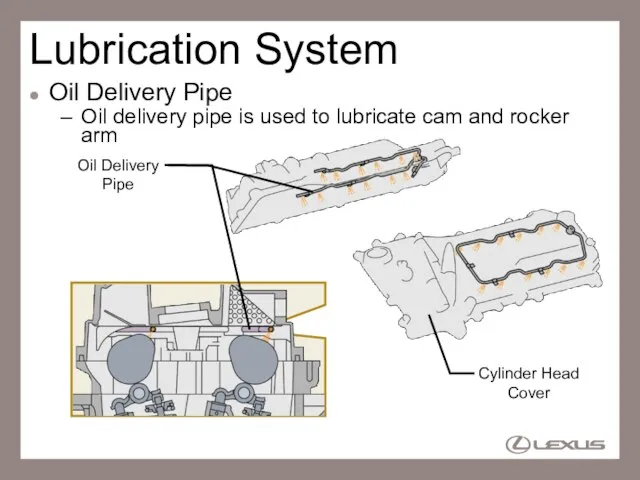
- 32. Lubrication System Oil Delivery Pipe Oil delivery pipe is used to lubricate cam and rocker arm
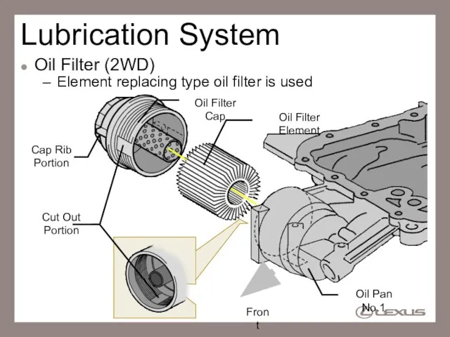
- 33. Lubrication System Oil Filter (2WD) Element replacing type oil filter is used Oil Filter Cap Oil
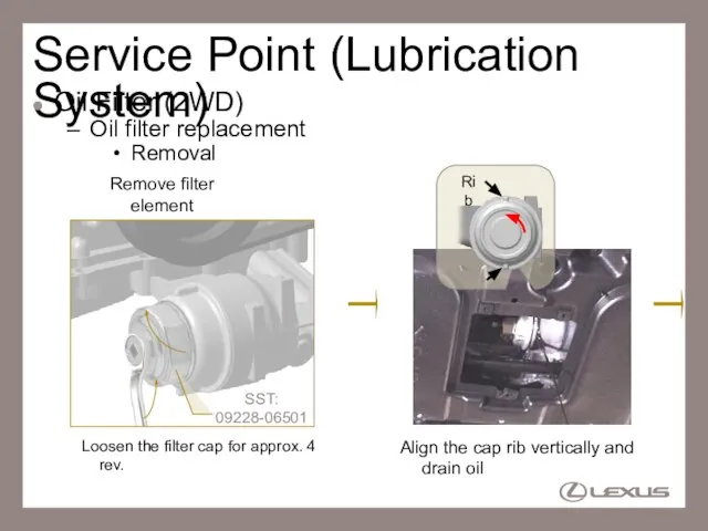
- 34. Service Point (Lubrication System) Oil Filter (2WD) Oil filter replacement Removal Loosen the filter cap for
- 35. Service Point (Lubrication System) Oil Filter (2WD) Oil filter replacement Removal Remove oil filter cap and
- 36. Service Point (Lubrication System) Oil Filter (2WD) Oil filter replacement Installation Set new filter element and
- 37. Service Point (Lubrication System) Oil Filter (2WD) Oil filter replacement Installation Refill engine oil Run the
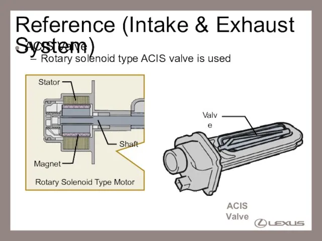
- 38. Intake and Exhaust System ACIS Valve Rotary solenoid type ACIS valve is used ACIS valve is
- 39. Reference (Intake & Exhaust System) ACIS Valve Rotary solenoid type ACIS valve is used Valve Rotary
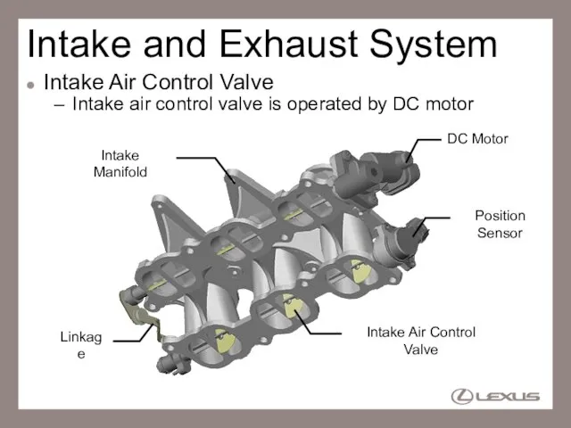
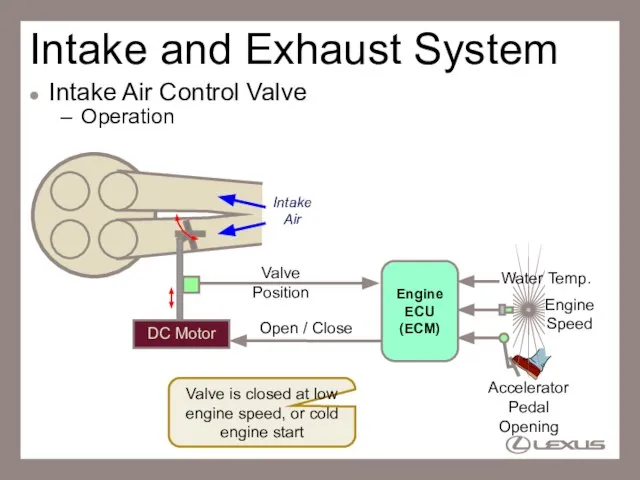
- 40. Intake and Exhaust System Intake Air Control Valve Intake air control valve is operated by DC
- 41. Valve is closed at low engine speed, or cold engine start Intake and Exhaust System Intake
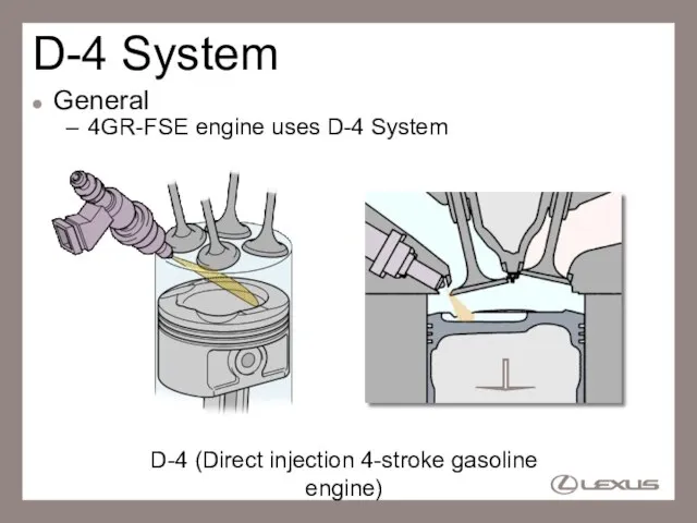
- 42. D-4 System General 4GR-FSE engine uses D-4 System D-4 (Direct injection 4-stroke gasoline engine)
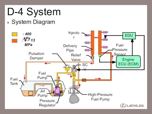
- 43. D-4 System System Diagram High-Pressure Fuel Pump Injector Fuel Pressure Sensor Fuel Tank Delivery Pipe Fuel
- 44. D-4 System Difference from usual gasoline EFI Injector Slit-nozzle type Injection pressure is 4 –13 MPa
- 45. Reference Features of D-4 System Direct Injection High Pressure Injection Slit-nozzle Injector Fuel does not adhere
- 46. D-4 System Location High-Pressure Fuel Pump Injector Fuel Pressure Sensor Delivery Pipe EDU Pulsation Damper
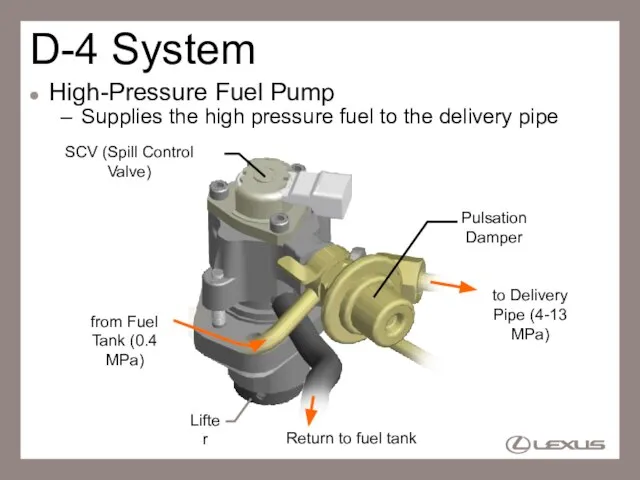
- 47. D-4 System High-Pressure Fuel Pump Supplies the high pressure fuel to the delivery pipe SCV (Spill
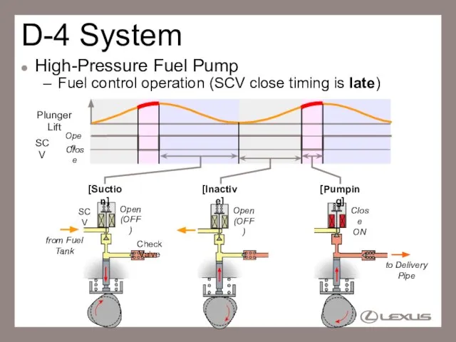
- 48. D-4 System High-Pressure Fuel Pump Fuel control operation (SCV close timing is late) Plunger Lift SCV
- 49. D-4 System High-Pressure Fuel Pump Fuel control operation (SCV close timing is early) Plunger Lift SCV
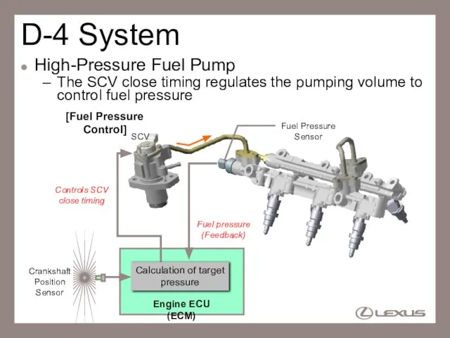
- 50. D-4 System High-Pressure Fuel Pump The SCV close timing regulates the pumping volume to control fuel
- 51. D-4 System Delivery Pipe Stores high-pressure fuel (4 – 13 MPa) produced by high-pressure fuel pump
- 52. D-4 System Delivery Pipe Fuel pressure sensor Fuel Pressure 0 19.6 0.5 4.5 Delivery Pipe Pressure
- 53. D-4 System Injector High pressure, slit-nozzle type injector Slit-nozzle
- 54. D-4 System Injector Slit-nozzle makes sector formed injection Sector Formed Injection 0.71 mm (0.028 in.) A
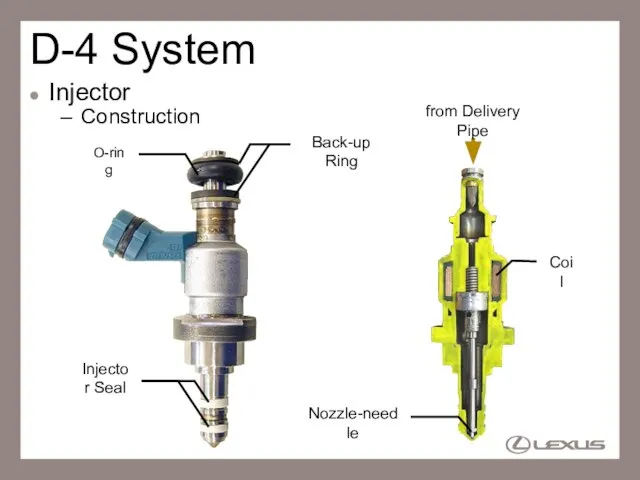
- 55. D-4 System Injector Construction Injector Seal Back-up Ring O-ring Nozzle-needle from Delivery Pipe Coil
- 56. Service Point (D-4 System) Injector When remove the injector from cylinder head, replace the injector seal
- 57. Service Point (D-4 System) Injector Replacement of injector seals (using SST) Needle-nosed Pliers 1. Remove injector
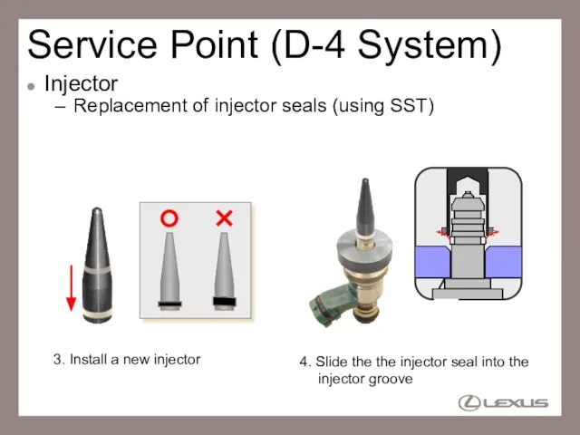
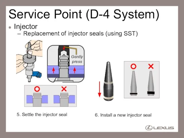
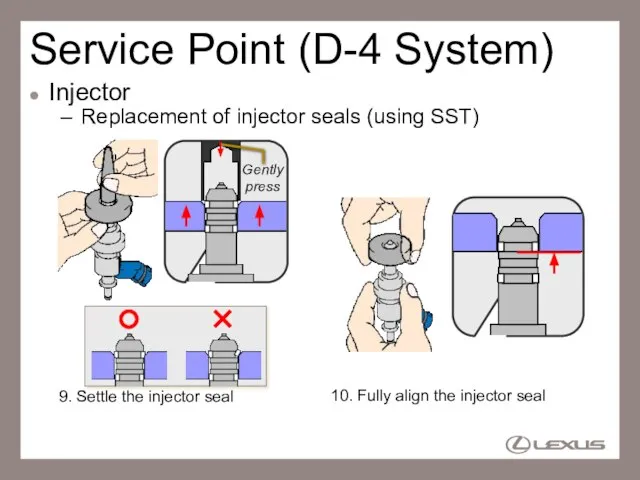
- 58. Service Point (D-4 System) Injector Replacement of injector seals (using SST) 3. Install a new injector
- 59. Service Point (D-4 System) Injector Replacement of injector seals (using SST) 6. Install a new injector
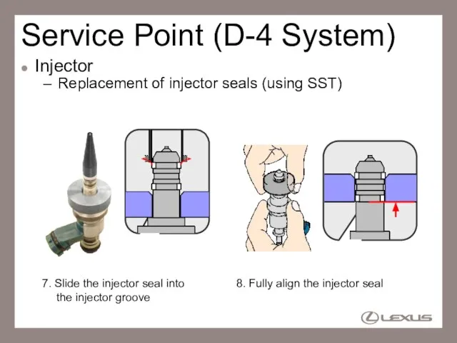
- 60. Service Point (D-4 System) Injector Replacement of injector seals (using SST) 8. Fully align the injector
- 61. Service Point (D-4 System) Injector Replacement of injector seals (using SST) 10. Fully align the injector
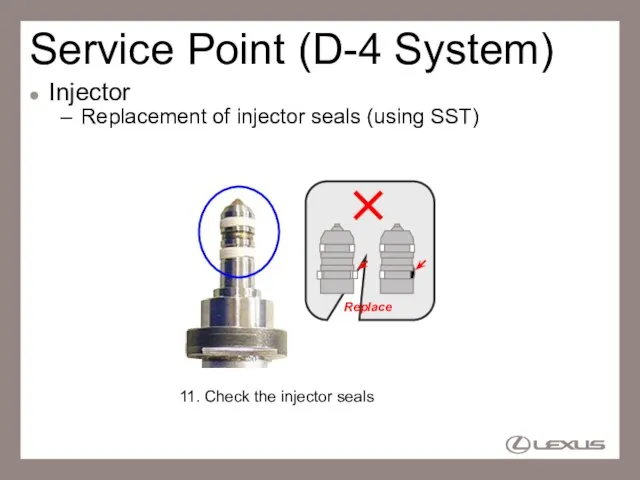
- 62. Service Point (D-4 System) Injector Replacement of injector seals (using SST) 11. Check the injector seals
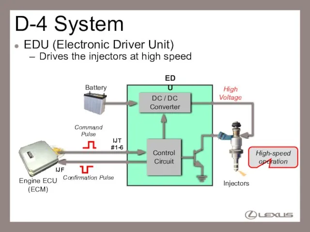
- 63. D-4 System EDU (Electronic Driver Unit) Drives the injectors at high speed Engine ECU (ECM) EDU
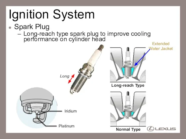
- 64. Ignition System Spark Plug Long-reach type spark plug to improve cooling performance on cylinder head Extended
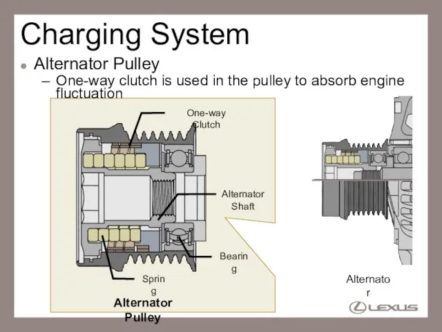
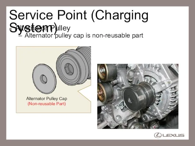
- 65. Charging System Alternator Pulley One-way clutch is used in the pulley to absorb engine fluctuation One-way
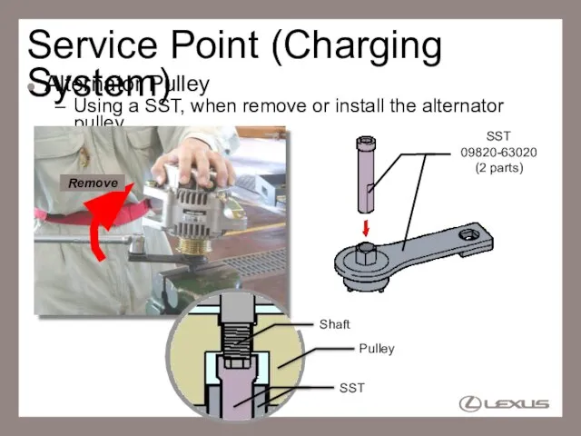
- 66. Service Point (Charging System) Alternator Pulley Using a SST, when remove or install the alternator pulley
- 67. Service Point (Charging System) Alternator Pulley Alternator pulley cap is non-reusable part Alternator Pulley Cap (Non-reusable
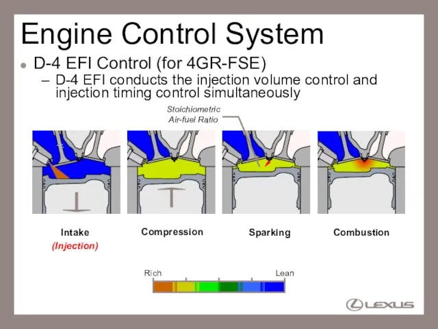
- 68. Engine Control System D-4 EFI Control (for 4GR-FSE) D-4 EFI conducts the injection volume control and
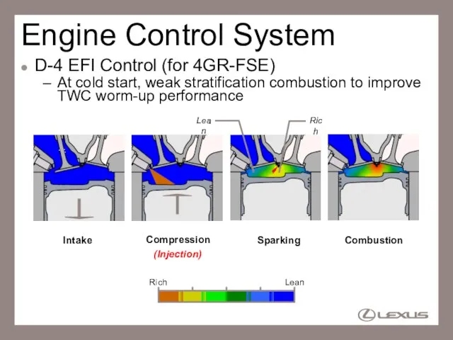
- 69. Engine Control System D-4 EFI Control (for 4GR-FSE) At cold start, weak stratification combustion to improve
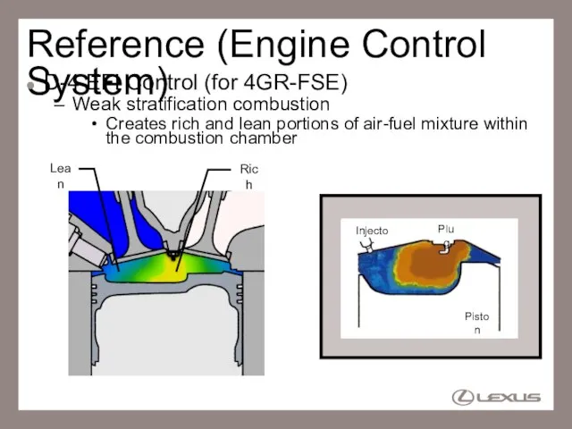
- 70. Reference (Engine Control System) D-4 EFI Control (for 4GR-FSE) Weak stratification combustion Creates rich and lean
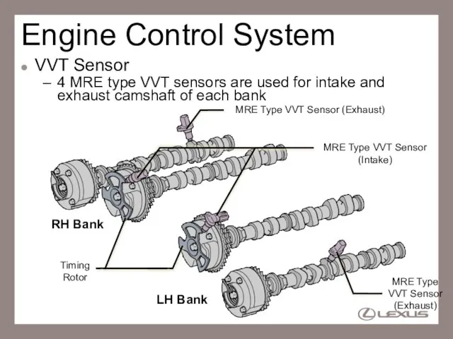
- 71. Engine Control System VVT Sensor 4 MRE type VVT sensors are used for intake and exhaust
- 72. Reference (Engine Control System) VVT Sensor Output signal is digital waveform MRE Type Pickup Coil Type
- 73. Reference (Engine Control System) VVT Sensor The resistance of MRE is changed by the magnetic flux
- 74. Reference (Engine Control System) VVT Sensor Signal output at extremely low speed rotation can be ensured
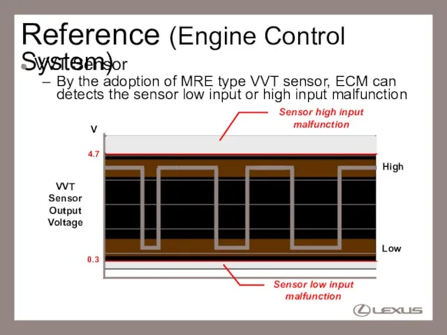
- 75. Reference (Engine Control System) VVT Sensor By the adoption of MRE type VVT sensor, ECM can
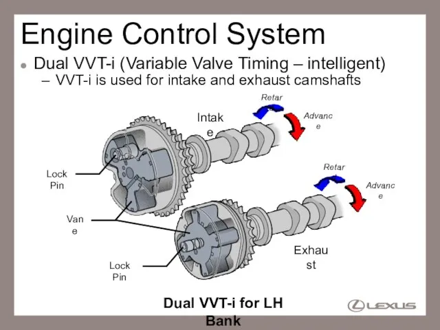
- 76. Engine Control System Dual VVT-i (Variable Valve Timing – intelligent) VVT-i is used for intake and
- 77. Reference (Engine Control System) Dual VVT-i Operation At Idle, Light Load, Low Temp. and Starting TDC
- 78. Reference (Engine Control System) Dual VVT-i Operation At Medium Load TDC BDC Increase internal EGR, Eliminate
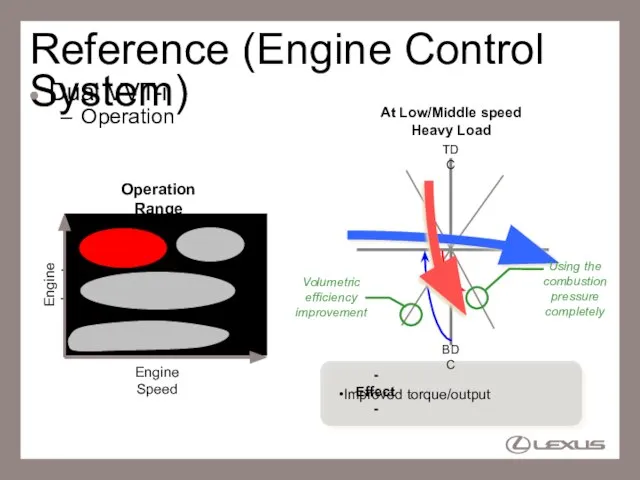
- 79. Reference (Engine Control System) Dual VVT-i Operation At Low/Middle speed Heavy Load TDC BDC Using the
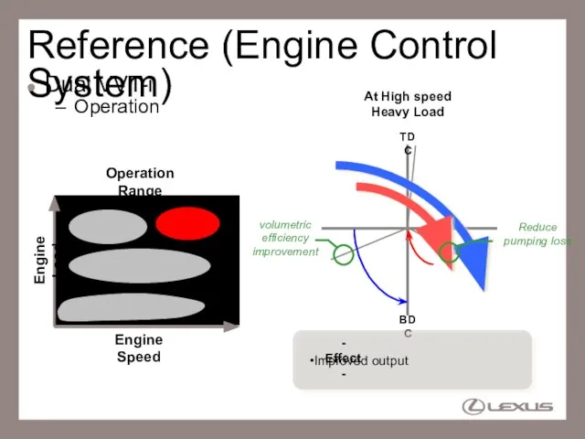
- 80. Reference (Engine Control System) Dual VVT-i Operation Engine Load Engine Speed At High speed Heavy Load
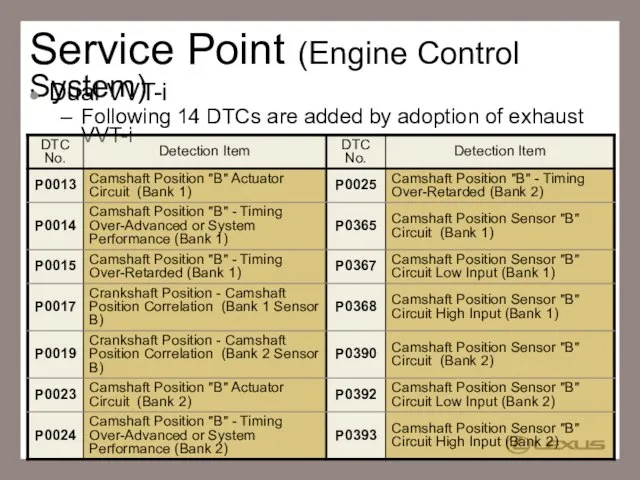
- 81. Service Point (Engine Control System) Dual VVT-i Following 14 DTCs are added by adoption of exhaust
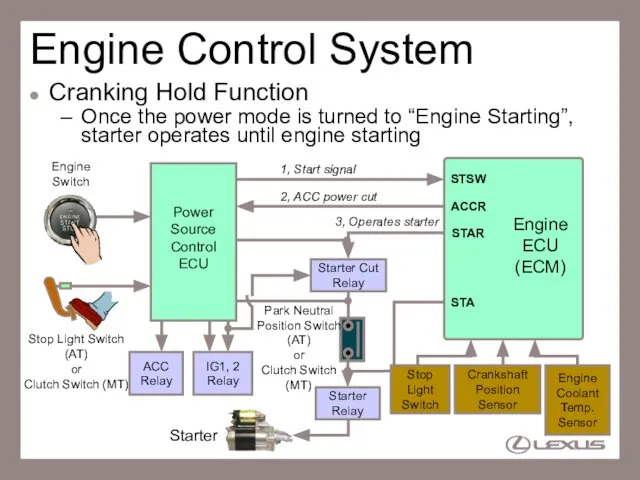
- 82. Engine Control System Cranking Hold Function Once the power mode is turned to “Engine Starting”, starter
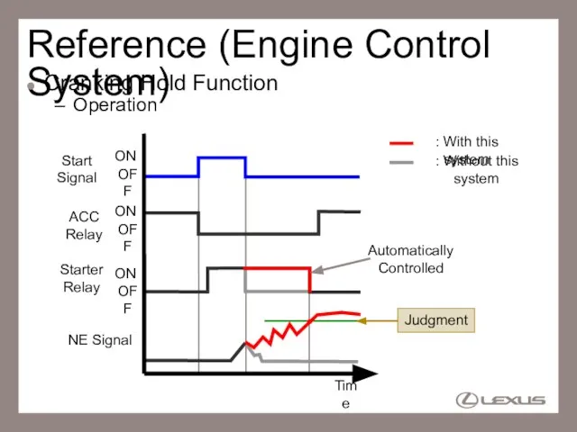
- 83. Reference (Engine Control System) Cranking Hold Function Operation Start Signal Starter Relay ACC Relay NE Signal
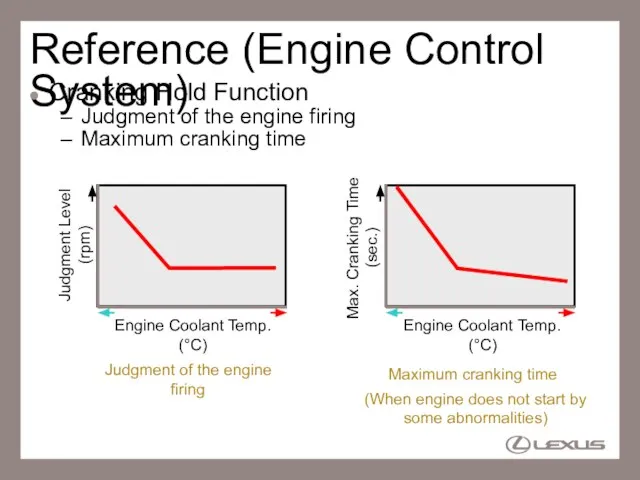
- 84. Reference (Engine Control System) Cranking Hold Function Judgment of the engine firing Maximum cranking time Engine
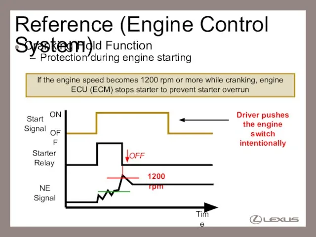
- 85. Reference (Engine Control System) Cranking Hold Function Protection during engine starting 1200 rpm OFF NE Signal
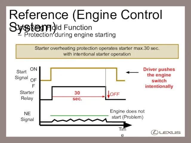
- 86. Reference (Engine Control System) Cranking Hold Function Protection during engine starting Engine does not start (Problem)
- 88. Скачать презентацию
Слайд 2Описание двигателя
Характеристики 4GR-FSE
3 Цепи газораспределения
Свечи зажигания с длинной юбкой
Масляный фильтр со сменным
Описание двигателя
Характеристики 4GR-FSE
3 Цепи газораспределения
Свечи зажигания с длинной юбкой
Масляный фильтр со сменным
Слайд 3Описание двигателя
Характеристики 4GR-FSE
Два механизма VVT-i
Проставка рубашки охлаждения
Гидрокомпенсатор клапанного зазора
Поворотный электромагнитный клапан
Описание двигателя
Характеристики 4GR-FSE
Два механизма VVT-i
Проставка рубашки охлаждения
Гидрокомпенсатор клапанного зазора
Поворотный электромагнитный клапан
Слайд 4Описание двигателя
Основные характеристики
Описание двигателя
Основные характеристики
Слайд 5Engine Proper
Cylinder Head
Camshaft housing to simply the cylinder head structure
Camshaft bearing cap
Engine Proper
Cylinder Head
Camshaft housing to simply the cylinder head structure
Camshaft bearing cap
Слайд 6Service Point (Engine Proper)
Cylinder Head
Camshaft and camshaft housing installation
LH Bank
Step1
: Temporary tighten
Service Point (Engine Proper)
Cylinder Head
Camshaft and camshaft housing installation
LH Bank
Step1
: Temporary tighten
Слайд 7Service Point (Engine Proper)
Cylinder Head
Camshaft and camshaft housing installation
LH Bank
Step2
: Tighten (Torque:
Service Point (Engine Proper)
Cylinder Head
Camshaft and camshaft housing installation
LH Bank
Step2
: Tighten (Torque:
Слайд 8Service Point (Engine Proper)
Cylinder Head
Camshaft and camshaft housing installation
LH Bank
Step3
: Tighten (Torque:
Service Point (Engine Proper)
Cylinder Head
Camshaft and camshaft housing installation
LH Bank
Step3
: Tighten (Torque:
Слайд 9Engine Proper
Cylinder Block
Water jacket spacer optimizes the cylinder bore temp. to reduce
Engine Proper
Cylinder Block
Water jacket spacer optimizes the cylinder bore temp. to reduce
Слайд 10Engine Proper
Cylinder Block
Spiny liner is used to increase cooling performance
Approx. 1.0 mm
Engine Proper
Cylinder Block
Spiny liner is used to increase cooling performance
Approx. 1.0 mm
Слайд 11Engine Proper
Piston
Optimal piston head shape to promote the mixture of fuel and
Engine Proper
Piston
Optimal piston head shape to promote the mixture of fuel and
Слайд 12Engine Proper
Bearing
Bearing without bearing claw is used for crankshaft bearings and connecting
Engine Proper
Bearing
Bearing without bearing claw is used for crankshaft bearings and connecting
Слайд 13Service Point (Engine Proper)
Installation of Crankshaft Upper Bearing
Bearing position should be centered
Service Point (Engine Proper)
Installation of Crankshaft Upper Bearing
Bearing position should be centered
Слайд 14Service Point (Engine Proper)
Installation of Crankshaft Lower Bearing, Connecting Rod Upper and
Service Point (Engine Proper)
Installation of Crankshaft Lower Bearing, Connecting Rod Upper and
Слайд 15Service Point (Engine Proper)
Crankshaft Bearing (upper and lower)
Combination of different width of
Service Point (Engine Proper)
Crankshaft Bearing (upper and lower)
Combination of different width of
Слайд 16Valve Mechanism
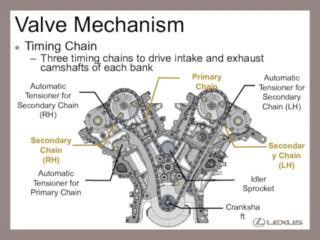
General
Three timing chains to drive intake and exhaust camshafts of each
Valve Mechanism
General
Three timing chains to drive intake and exhaust camshafts of each
Слайд 17Valve Mechanism
Camshaft
VVT-i system is used for intake & exhaust camshafts (Dual VVT-i)
VVT-i
Valve Mechanism
Camshaft
VVT-i system is used for intake & exhaust camshafts (Dual VVT-i)
VVT-i
Слайд 18Valve Mechanism
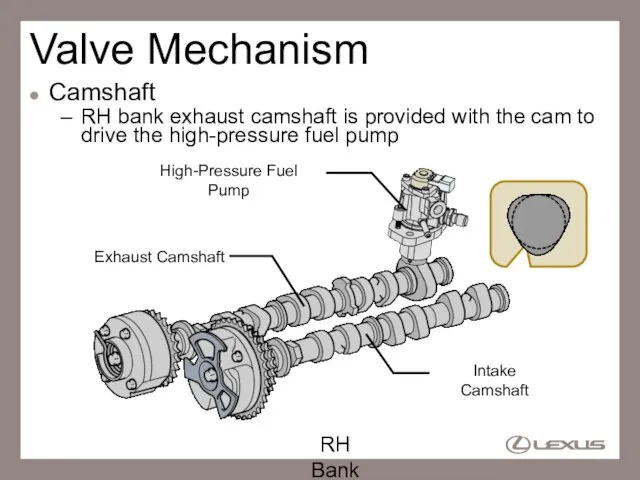
Camshaft
RH bank exhaust camshaft is provided with the cam to drive
Valve Mechanism
Camshaft
RH bank exhaust camshaft is provided with the cam to drive
Слайд 19Valve Mechanism
Timing Chain
Three timing chains to drive intake and exhaust camshafts of
Valve Mechanism
Timing Chain
Three timing chains to drive intake and exhaust camshafts of
Слайд 20Valve Mechanism
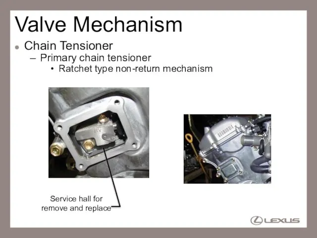
Chain Tensioner
Primary chain tensioner
Ratchet type non-return mechanism
Service hall for
Valve Mechanism
Chain Tensioner
Primary chain tensioner
Ratchet type non-return mechanism
Service hall for
Слайд 21Valve Mechanism
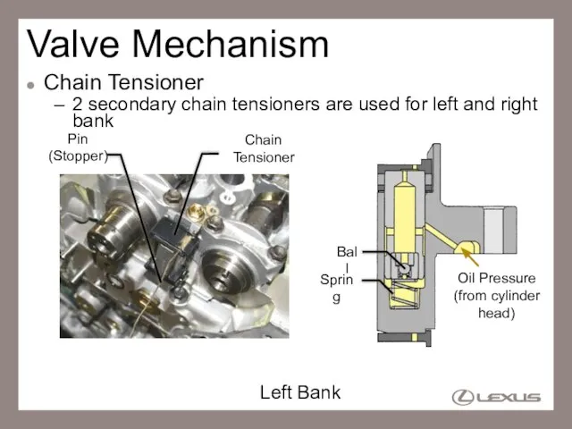
Chain Tensioner
2 secondary chain tensioners are used for left and right
Valve Mechanism
Chain Tensioner
2 secondary chain tensioners are used for left and right
Слайд 22Reference (Valve Mechanism)
Hydraulic Lash Adjuster
Maintaining a constant zero valve clearance through use
Reference (Valve Mechanism)
Hydraulic Lash Adjuster
Maintaining a constant zero valve clearance through use
Слайд 23Reference (Valve Mechanism)
Hydraulic Lash Adjuster
Start cam lift, plunger is pressed and oil
Reference (Valve Mechanism)
Hydraulic Lash Adjuster
Start cam lift, plunger is pressed and oil
Слайд 24Reference (Valve Mechanism)
Hydraulic Lash Adjuster
Then the rocker arm pushes the valve by
Reference (Valve Mechanism)
Hydraulic Lash Adjuster
Then the rocker arm pushes the valve by
Слайд 25Reference (Valve Mechanism)
Hydraulic Lash Adjuster
Plunger pushes back, check valve is opened and
Reference (Valve Mechanism)
Hydraulic Lash Adjuster
Plunger pushes back, check valve is opened and
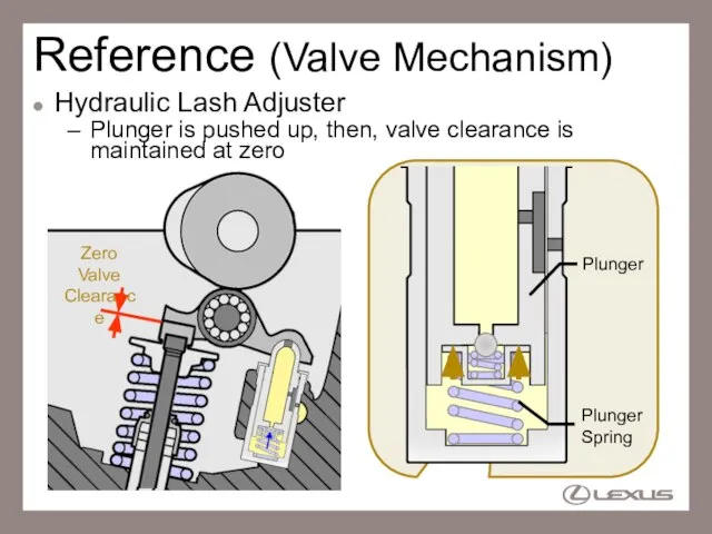
Слайд 26Zero Valve Clearance
Reference (Valve Mechanism)
Hydraulic Lash Adjuster
Plunger is pushed up, then, valve
Zero Valve Clearance
Reference (Valve Mechanism)
Hydraulic Lash Adjuster
Plunger is pushed up, then, valve
Слайд 27Reference (Valve Mechanism)
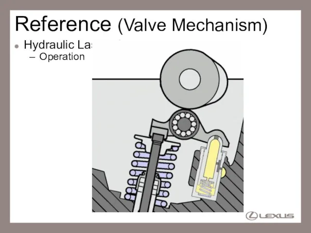
Hydraulic Lash Adjuster
Operation
Reference (Valve Mechanism)
Hydraulic Lash Adjuster
Operation
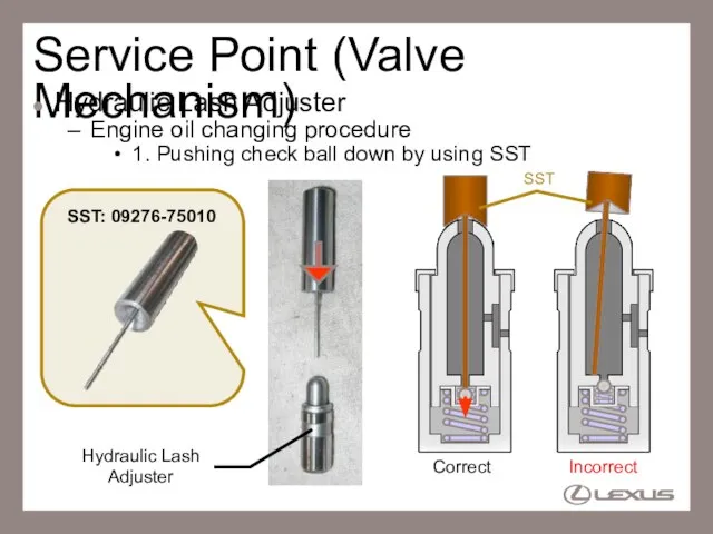
Слайд 28Service Point (Valve Mechanism)
Hydraulic Lash Adjuster
Engine oil changing procedure
1. Pushing check ball
Service Point (Valve Mechanism)
Hydraulic Lash Adjuster
Engine oil changing procedure
1. Pushing check ball
Слайд 29Service Point (Valve Mechanism)
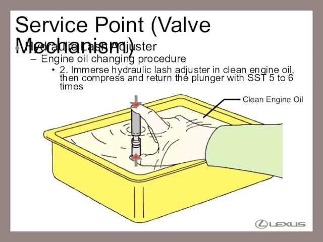
Hydraulic Lash Adjuster
Engine oil changing procedure
2. Immerse hydraulic lash
Service Point (Valve Mechanism)
Hydraulic Lash Adjuster
Engine oil changing procedure
2. Immerse hydraulic lash
Слайд 30Service Point (Valve Mechanism)
Hydraulic Lash Adjuster
Engine oil changing procedure
3. Press the plunger
Service Point (Valve Mechanism)
Hydraulic Lash Adjuster
Engine oil changing procedure
3. Press the plunger
Слайд 31Service Point (Valve Mechanism)
Hydraulic Lash Adjuster
Engine oil changing procedure
If plunger is compressed
Service Point (Valve Mechanism)
Hydraulic Lash Adjuster
Engine oil changing procedure
If plunger is compressed

Слайд 32Lubrication System
Oil Delivery Pipe
Oil delivery pipe is used to lubricate cam and
Lubrication System
Oil Delivery Pipe
Oil delivery pipe is used to lubricate cam and
Слайд 33Lubrication System
Oil Filter (2WD)
Element replacing type oil filter is used
Oil Filter Cap
Oil
Lubrication System
Oil Filter (2WD)
Element replacing type oil filter is used
Oil Filter Cap
Oil
Слайд 34Service Point (Lubrication System)
Oil Filter (2WD)
Oil filter replacement
Removal
Loosen the filter cap
Service Point (Lubrication System)
Oil Filter (2WD)
Oil filter replacement
Removal
Loosen the filter cap
Слайд 35Service Point (Lubrication System)
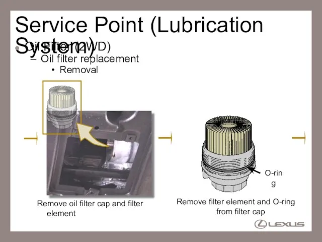
Oil Filter (2WD)
Oil filter replacement
Removal
Remove oil filter cap and
Service Point (Lubrication System)
Oil Filter (2WD)
Oil filter replacement
Removal
Remove oil filter cap and
Слайд 36Service Point (Lubrication System)
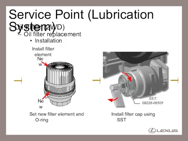
Oil Filter (2WD)
Oil filter replacement
Installation
Set new filter element and
Service Point (Lubrication System)
Oil Filter (2WD)
Oil filter replacement
Installation
Set new filter element and
Слайд 37Service Point (Lubrication System)
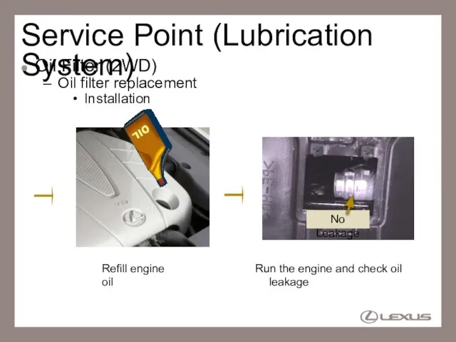
Oil Filter (2WD)
Oil filter replacement
Installation
Refill engine oil
Run the engine
Service Point (Lubrication System)
Oil Filter (2WD)
Oil filter replacement
Installation
Refill engine oil
Run the engine
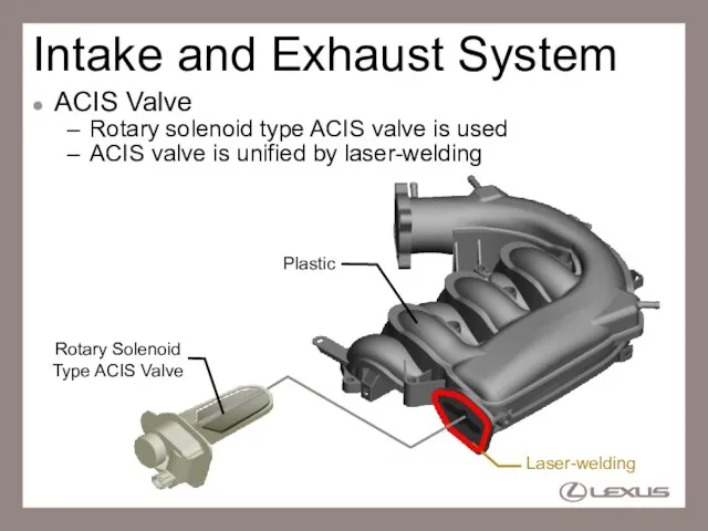
Слайд 38Intake and Exhaust System
ACIS Valve
Rotary solenoid type ACIS valve is used
ACIS
Intake and Exhaust System
ACIS Valve
Rotary solenoid type ACIS valve is used
ACIS
Слайд 39Reference (Intake & Exhaust System)
ACIS Valve
Rotary solenoid type ACIS valve is used
Valve
Rotary
Reference (Intake & Exhaust System)
ACIS Valve
Rotary solenoid type ACIS valve is used
Valve
Rotary
Слайд 40Intake and Exhaust System
Intake Air Control Valve
Intake air control valve is
Intake and Exhaust System
Intake Air Control Valve
Intake air control valve is
Слайд 41Valve is closed at low engine speed, or cold engine start
Intake and
Valve is closed at low engine speed, or cold engine start
Intake and
Слайд 42D-4 System
General
4GR-FSE engine uses D-4 System
D-4 (Direct injection 4-stroke gasoline engine)
D-4 System
General
4GR-FSE engine uses D-4 System
D-4 (Direct injection 4-stroke gasoline engine)
Слайд 43D-4 System
System Diagram
High-Pressure Fuel Pump
Injector
Fuel Pressure Sensor
Fuel Tank
Delivery Pipe
Fuel Pump
Pressure Regulator
: 4
D-4 System
System Diagram
High-Pressure Fuel Pump
Injector
Fuel Pressure Sensor
Fuel Tank
Delivery Pipe
Fuel Pump
Pressure Regulator
: 4
Слайд 44D-4 System
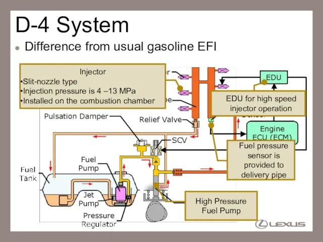
Difference from usual gasoline EFI
Injector
Slit-nozzle type
Injection pressure is 4 –13 MPa
D-4 System
Difference from usual gasoline EFI
Injector
Slit-nozzle type
Injection pressure is 4 –13 MPa
Слайд 45Reference
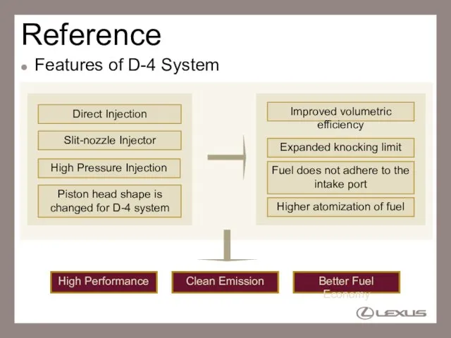
Features of D-4 System
Direct Injection
High Pressure Injection
Slit-nozzle Injector
Fuel does not adhere to
Reference
Features of D-4 System
Direct Injection
High Pressure Injection
Slit-nozzle Injector
Fuel does not adhere to
Слайд 46D-4 System
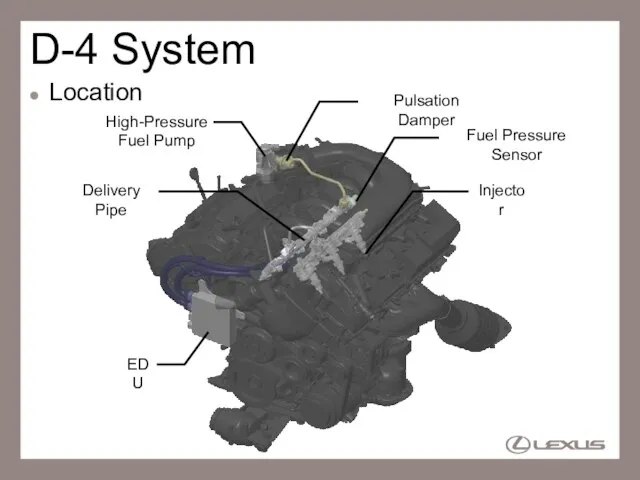
Location
High-Pressure Fuel Pump
Injector
Fuel Pressure Sensor
Delivery Pipe
EDU
Pulsation Damper
D-4 System
Location
High-Pressure Fuel Pump
Injector
Fuel Pressure Sensor
Delivery Pipe
EDU
Pulsation Damper
Слайд 47D-4 System
High-Pressure Fuel Pump
Supplies the high pressure fuel to the delivery pipe
SCV
D-4 System
High-Pressure Fuel Pump
Supplies the high pressure fuel to the delivery pipe
SCV
Слайд 48D-4 System
High-Pressure Fuel Pump
Fuel control operation (SCV close timing is late)
Plunger Lift
SCV
Open
Close
Close
ON
Open
(OFF)
Open
(OFF)
[Suction]
[Inactive]
Check
D-4 System
High-Pressure Fuel Pump
Fuel control operation (SCV close timing is late)
Plunger Lift
SCV
Open
Close
Close
ON
Open
(OFF)
Open
(OFF)
[Suction]
[Inactive]
Check
Слайд 49D-4 System
High-Pressure Fuel Pump
Fuel control operation (SCV close timing is early)
Plunger Lift
SCV
Open
Close
Close
(ON)
Open
(OFF)
Open
(OFF)
[Suction]
[Inactive]
[Pumping]
Check
D-4 System
High-Pressure Fuel Pump
Fuel control operation (SCV close timing is early)
Plunger Lift
SCV
Open
Close
Close
(ON)
Open
(OFF)
Open
(OFF)
[Suction]
[Inactive]
[Pumping]
Check
Слайд 50D-4 System
High-Pressure Fuel Pump
The SCV close timing regulates the pumping volume to
D-4 System
High-Pressure Fuel Pump
The SCV close timing regulates the pumping volume to
Слайд 51D-4 System
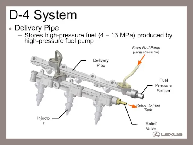
Delivery Pipe
Stores high-pressure fuel (4 – 13 MPa) produced by high-pressure
D-4 System
Delivery Pipe
Stores high-pressure fuel (4 – 13 MPa) produced by high-pressure
Слайд 52D-4 System
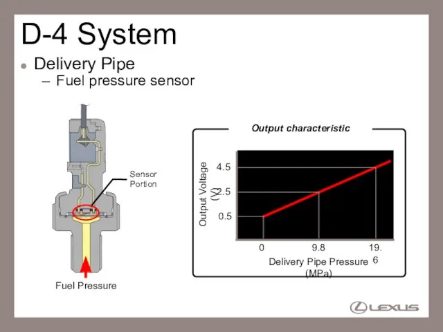
Delivery Pipe
Fuel pressure sensor
Fuel Pressure
0
19.6
0.5
4.5
Delivery Pipe Pressure (MPa)
Output Voltage (V)
Output characteristic
D-4 System
Delivery Pipe
Fuel pressure sensor
Fuel Pressure
0
19.6
0.5
4.5
Delivery Pipe Pressure (MPa)
Output Voltage (V)
Output characteristic
Слайд 53D-4 System
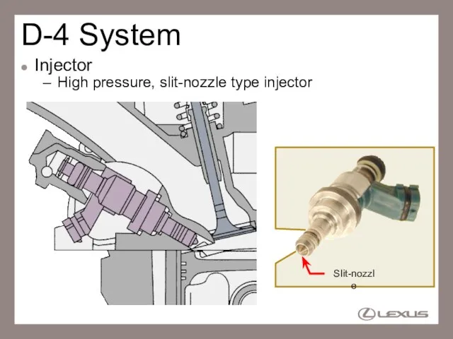
Injector
High pressure, slit-nozzle type injector
Slit-nozzle
D-4 System
Injector
High pressure, slit-nozzle type injector
Slit-nozzle
Слайд 54D-4 System
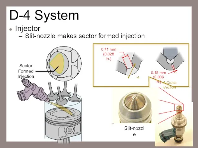
Injector
Slit-nozzle makes sector formed injection
Sector Formed Injection
0.71 mm
(0.028 in.)
A
0.15 mm
(0.006 in.)
A
D-4 System
Injector
Slit-nozzle makes sector formed injection
Sector Formed Injection
0.71 mm
(0.028 in.)
A
0.15 mm
(0.006 in.)
A
Слайд 55D-4 System
Injector
Construction
Injector Seal
Back-up Ring
O-ring
Nozzle-needle
from Delivery Pipe
Coil
D-4 System
Injector
Construction
Injector Seal
Back-up Ring
O-ring
Nozzle-needle
from Delivery Pipe
Coil
Слайд 56Service Point (D-4 System)
Injector
When remove the injector from cylinder head, replace the
Service Point (D-4 System)
Injector
When remove the injector from cylinder head, replace the
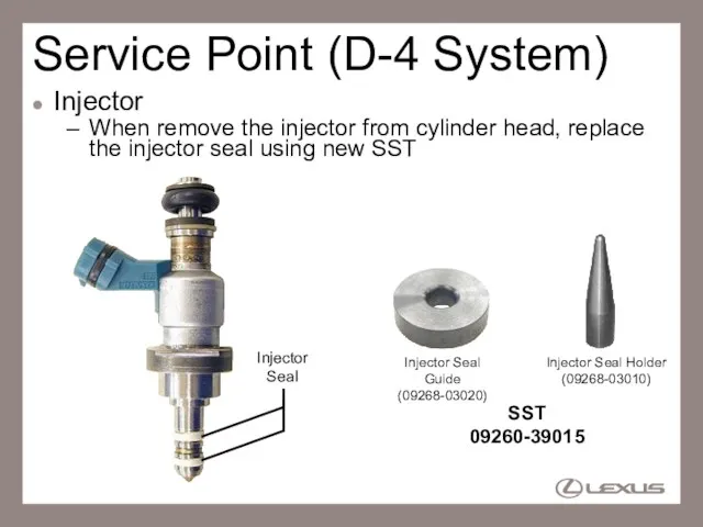
Слайд 57Service Point (D-4 System)
Injector
Replacement of injector seals (using SST)
Needle-nosed Pliers
1. Remove injector
Service Point (D-4 System)
Injector
Replacement of injector seals (using SST)
Needle-nosed Pliers
1. Remove injector
Слайд 58Service Point (D-4 System)
Injector
Replacement of injector seals (using SST)
3. Install a new
Service Point (D-4 System)
Injector
Replacement of injector seals (using SST)
3. Install a new
Слайд 59Service Point (D-4 System)
Injector
Replacement of injector seals (using SST)
6. Install a new
Service Point (D-4 System)
Injector
Replacement of injector seals (using SST)
6. Install a new
Слайд 60Service Point (D-4 System)
Injector
Replacement of injector seals (using SST)
8. Fully align the
Service Point (D-4 System)
Injector
Replacement of injector seals (using SST)
8. Fully align the
Слайд 61Service Point (D-4 System)
Injector
Replacement of injector seals (using SST)
10. Fully align the
Service Point (D-4 System)
Injector
Replacement of injector seals (using SST)
10. Fully align the
Слайд 62Service Point (D-4 System)
Injector
Replacement of injector seals (using SST)
11. Check the injector
Service Point (D-4 System)
Injector
Replacement of injector seals (using SST)
11. Check the injector
Слайд 63D-4 System
EDU (Electronic Driver Unit)
Drives the injectors at high speed
Engine ECU (ECM)
EDU
Injectors
High
D-4 System
EDU (Electronic Driver Unit)
Drives the injectors at high speed
Engine ECU (ECM)
EDU
Injectors
High
Слайд 64Ignition System
Spark Plug
Long-reach type spark plug to improve cooling performance on cylinder
Ignition System
Spark Plug
Long-reach type spark plug to improve cooling performance on cylinder
Слайд 65Charging System
Alternator Pulley
One-way clutch is used in the pulley to absorb engine
Charging System
Alternator Pulley
One-way clutch is used in the pulley to absorb engine
Слайд 66Service Point (Charging System)
Alternator Pulley
Using a SST, when remove or install the
Service Point (Charging System)
Alternator Pulley
Using a SST, when remove or install the
Слайд 67Service Point (Charging System)
Alternator Pulley
Alternator pulley cap is non-reusable part
Alternator Pulley Cap
(Non-reusable
Service Point (Charging System)
Alternator Pulley
Alternator pulley cap is non-reusable part
Alternator Pulley Cap
(Non-reusable
Слайд 68Engine Control System
D-4 EFI Control (for 4GR-FSE)
D-4 EFI conducts the injection volume
Engine Control System
D-4 EFI Control (for 4GR-FSE)
D-4 EFI conducts the injection volume
Слайд 69Engine Control System
D-4 EFI Control (for 4GR-FSE)
At cold start, weak stratification combustion
Engine Control System
D-4 EFI Control (for 4GR-FSE)
At cold start, weak stratification combustion
Слайд 70Reference (Engine Control System)
D-4 EFI Control (for 4GR-FSE)
Weak stratification combustion
Creates rich
Reference (Engine Control System)
D-4 EFI Control (for 4GR-FSE)
Weak stratification combustion
Creates rich
Слайд 71Engine Control System
VVT Sensor
4 MRE type VVT sensors are used for intake
Engine Control System
VVT Sensor
4 MRE type VVT sensors are used for intake
Слайд 72Reference (Engine Control System)
VVT Sensor
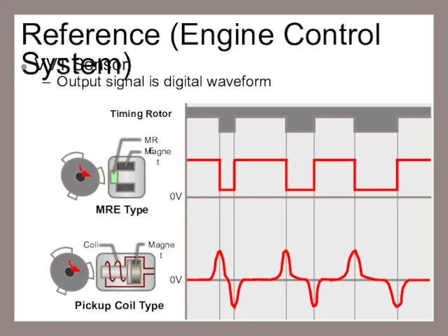
Output signal is digital waveform
MRE Type
Pickup Coil
Reference (Engine Control System)
VVT Sensor
Output signal is digital waveform
MRE Type
Pickup Coil
Слайд 73Reference (Engine Control System)
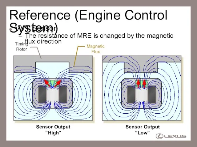
VVT Sensor
The resistance of MRE is changed by the
Reference (Engine Control System)
VVT Sensor
The resistance of MRE is changed by the
Слайд 74Reference (Engine Control System)
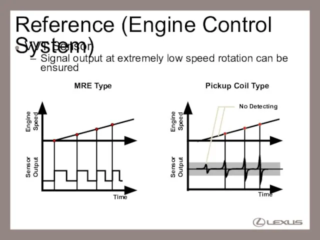
VVT Sensor
Signal output at extremely low speed rotation can
Reference (Engine Control System)
VVT Sensor
Signal output at extremely low speed rotation can
Слайд 75Reference (Engine Control System)
VVT Sensor
By the adoption of MRE type VVT sensor,
Reference (Engine Control System)
VVT Sensor
By the adoption of MRE type VVT sensor,
Слайд 76Engine Control System
Dual VVT-i (Variable Valve Timing – intelligent)
VVT-i is used for
Engine Control System
Dual VVT-i (Variable Valve Timing – intelligent)
VVT-i is used for
Слайд 77Reference (Engine Control System)
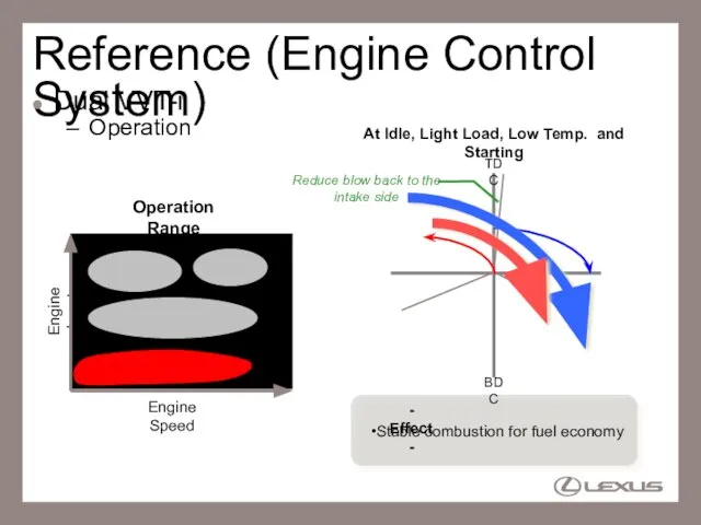
Dual VVT-i
Operation
At Idle, Light Load, Low Temp. and Starting
TDC
BDC
Reduce
Reference (Engine Control System)
Dual VVT-i
Operation
At Idle, Light Load, Low Temp. and Starting
TDC
BDC
Reduce
Слайд 78Reference (Engine Control System)
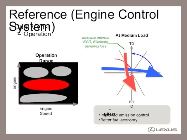
Dual VVT-i
Operation
At Medium Load
TDC
BDC
Increase internal EGR, Eliminate pumping loss
Engine
Reference (Engine Control System)
Dual VVT-i
Operation
At Medium Load
TDC
BDC
Increase internal EGR, Eliminate pumping loss
Engine
Слайд 79Reference (Engine Control System)
Dual VVT-i
Operation
At Low/Middle speed
Heavy Load
TDC
BDC
Using the combustion pressure completely
Reference (Engine Control System)
Dual VVT-i
Operation
At Low/Middle speed
Heavy Load
TDC
BDC
Using the combustion pressure completely
Слайд 80Reference (Engine Control System)
Dual VVT-i
Operation
Engine Load
Engine Speed
At High speed
Heavy Load
Operation Range
TDC
BDC
volumetric efficiency
Reference (Engine Control System)
Dual VVT-i
Operation
Engine Load
Engine Speed
At High speed
Heavy Load
Operation Range
TDC
BDC
volumetric efficiency
Слайд 81Service Point (Engine Control System)
Dual VVT-i
Following 14 DTCs are added by adoption
Service Point (Engine Control System)
Dual VVT-i
Following 14 DTCs are added by adoption
Слайд 82Engine Control System
Cranking Hold Function
Once the power mode is turned to “Engine
Engine Control System
Cranking Hold Function
Once the power mode is turned to “Engine
Слайд 83Reference (Engine Control System)
Cranking Hold Function
Operation
Start Signal
Starter Relay
ACC Relay
NE Signal
Time
ON
Automatically Controlled
Judgment
OFF
ON
OFF
ON
OFF
Reference (Engine Control System)
Cranking Hold Function
Operation
Start Signal
Starter Relay
ACC Relay
NE Signal
Time
ON
Automatically Controlled
Judgment
OFF
ON
OFF
ON
OFF
Слайд 84Reference (Engine Control System)
Cranking Hold Function
Judgment of the engine firing
Maximum cranking time
Engine
Reference (Engine Control System)
Cranking Hold Function
Judgment of the engine firing
Maximum cranking time
Engine
Слайд 85Reference (Engine Control System)
Cranking Hold Function
Protection during engine starting
1200 rpm
OFF
NE Signal
ON
Start Signal
OFF
Starter
Reference (Engine Control System)
Cranking Hold Function
Protection during engine starting
1200 rpm
OFF
NE Signal
ON
Start Signal
OFF
Starter
Слайд 86Reference (Engine Control System)
Cranking Hold Function
Protection during engine starting
Engine does not start
Reference (Engine Control System)
Cranking Hold Function
Protection during engine starting
Engine does not start
 Young people. What are they like
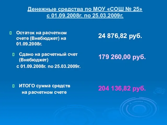 24 876,82 руб.
 Литье металлов 8 класс
 Дизайн-проект автомата для приема пластиковых бутылок
 Звуки [ Г ] [ Г ' ]. Буквы Г, г
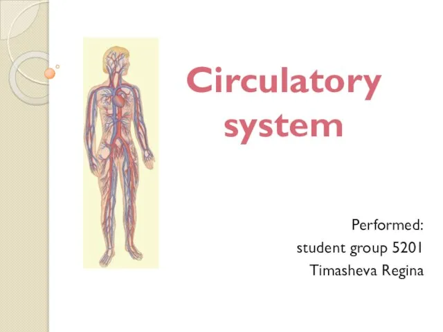 Кровяносная система
 Духовная жизнь в 1930-е гг.
 На пути к мечте
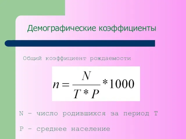 Демографические коэффициенты
 ЗВУКИ И БУКВЫ, ПРОИЗНОШЕНИЕ И ПРАВОПИСАНИЕ
 Изготовление снежинки 1-2 класс
 Презентация на тему Фламинго
  Системы тяги и тягового электроснабжения
 Взаимосвязь имиджа региона и продукции в их продвижении(на примере Беларуси)
 Технология саморазвития личности школьника
 Аналитическая записка по теме 3.3. Информационное обеспечение международной перевозки грузов Безнощук Богдан, Белоглазова Юлия, Б
 Использование альтернативных источников энергии
 Правописание приставок (5 класс)
 Неопределённые местоимения
 Лексика и фразеология (7 класс)
 Новые нормативные документы в области строительных металлоконструкций и их реализация в SCAD Office
 ЛИНС-М
 Что дает лес человеку?
 Преимущества предлагаемой технологии сухого совместного помола для цеха мелких силикатных блоков 1. Снижение расхода цемента на 1
  Презентация по английскому Католическая церковь
  Как найти идею
 Воображение
 Методика обучения технике нападения и тактике персональной защиты