- VRF_EHS-Installation_GL_EN_2019_Ver1.0_Cycle

Содержание
- 2. Modification history
- 3. Process and General installation guide Tank Integrated Hydro unit Split outdoor unit Mono outdoor unit External
- 4. Process Before start What is EHS Nomenclature Preparation of installation General guide of pipe drawing Installation
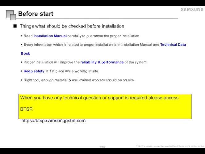
- 5. Before start ▶ Read Installation Manual carefully to guarantee the proper installation ▶ Every information which
- 6. What is EHS What is EHS Heating or Cooling can be used with Hot or Cold
- 7. System Types – Tank Integrated Split What is EHS Both water heating and hot water supply
- 8. System Types – Tank Integrated Mono What is EHS Both water heating and hot water supply
- 10. Preparation of installation Precautions IMPORTANT: When installing the unit, always remember to connect first the refrigerant
- 11. Preparation of installation Precautions ▶ Upon leakage of the refrigerant, ventilate the room.When the leaked refrigerant
- 12. Indoor unit / Outdoor unit compatibility Preparation of installation
- 13. Move the unit ▷ Moving the indoor unit with a fork lift - elect the moving
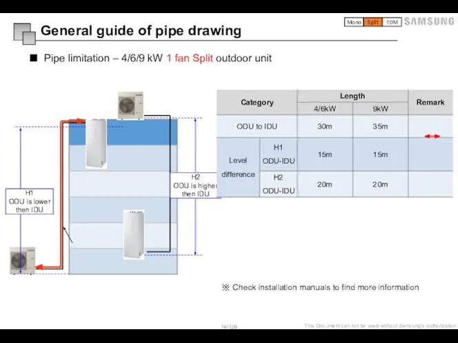
- 14. Pipe limitation – 4/6/9 kW 1 fan Split outdoor unit General guide of pipe drawing H1
- 15. Additional refrigerant charging [ SPLIT ] Mono Split TDM
- 16. - Use a tube Cutter ASTM standard copper pipe Follow the minimum thickness & temper grade.
- 17. Nitrogen gas blowing Nitrogen gas blowing - To prevent buildup of non-condensable substances in the refrigerant
- 18. Nitrogen gas blowing Nitrogen gas blowing Good Bad open open Nitrogen is not available to stay
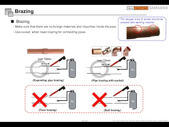
- 19. - Make sure that there are no foreign materials and impurities inside the pipe. - Use
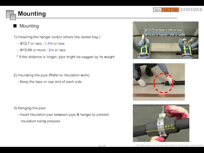
- 20. 1) Installing the hanger bolt(or others like ladder tray ) - Φ12.7 or less : 1.5m
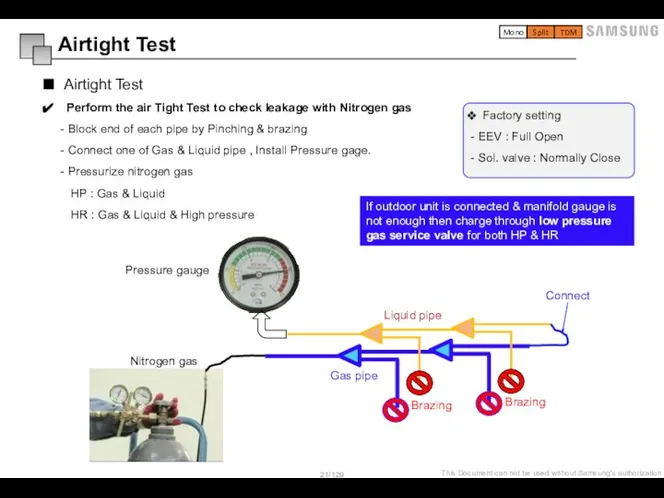
- 21. Perform the air Tight Test to check leakage with Nitrogen gas - Block end of each
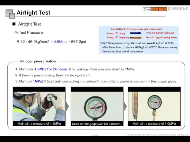
- 22. ※ Test Pressure - R-32 : 46.9kgf/cm2 = 4.6Mpa = 667.2psi 1. Maintains 4.6MPa for 24
- 23. 1) Insulate the refrigerant pipe based on the proper thickness of insulator for each pipe size.
- 24. Put the pipe in EPDM insulation carefully so that the pipe will not get damaged with
- 25. - Refrigerant pipe before EEV kit or without EEV kit You can contact the gas side
- 26. Wire pipe (tube) Selection of wire and circuit breaker Install the pipe (tube) for power and
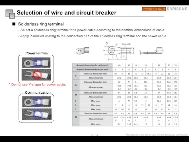
- 27. - Select a solderless ring terminal for a power cable according to the nominal dimensions of
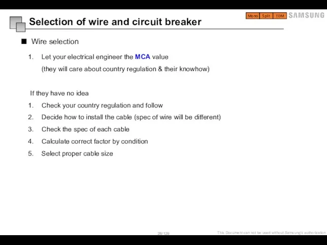
- 28. Wire selection Selection of wire and circuit breaker Let your electrical engineer the MCA value (they
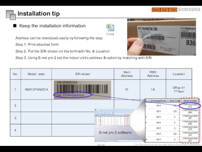
- 29. Address can be check(set) easily by following the step Step 1. Print attached form Step 2.
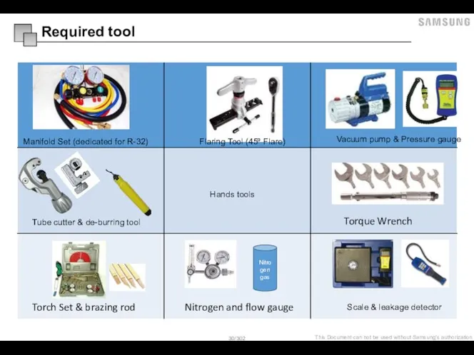
- 30. Required tool Tube cutter & de-burring tool Hands tools Manifold Set (dedicated for R-32) Flaring Tool
- 31. Tank intergrated Hydro unit Example of application Installation information Mounting the Hydro unit Charging a water
- 32. 1. Space heating + Water heating Example of application An example of field supply scope space
- 33. 2. Hybrid application (Back-up boiler and solar panel connected) Example of application Mono Split TDM An
- 34. Accessories Installation information Mono Split
- 35. Split Main components Mono Split
- 36. Mono Mono Split
- 37. Dimensional drawing of Hydro unit Installation information Mono Split
- 38. Installation of the Indoor unit Installation information The indoor unit should be installed indoors and meet
- 39. Mounting the Hydro unit Installation information A minimum of two people should lift the unit by
- 40. Base construction and installation of the Tank hydro unit Installation information Manufacturer is not responsible for
- 41. Drain Work Installation information In the cooling operation, defrost water may be produced from the pipes
- 42. Refrigerant pipe work Charging a water into the system For all guide lines, specifications regarding refrigerant
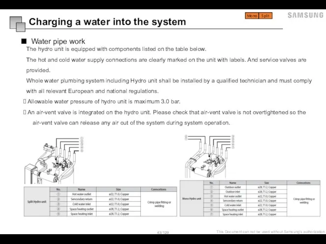
- 43. Water pipe work Charging a water into the system The hydro unit is equipped with components
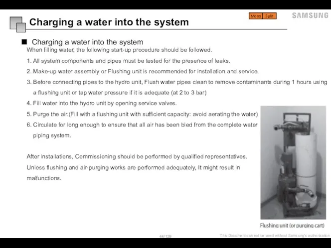
- 44. Charging a water into the system When filling water, the following start-up procedure should be followed.
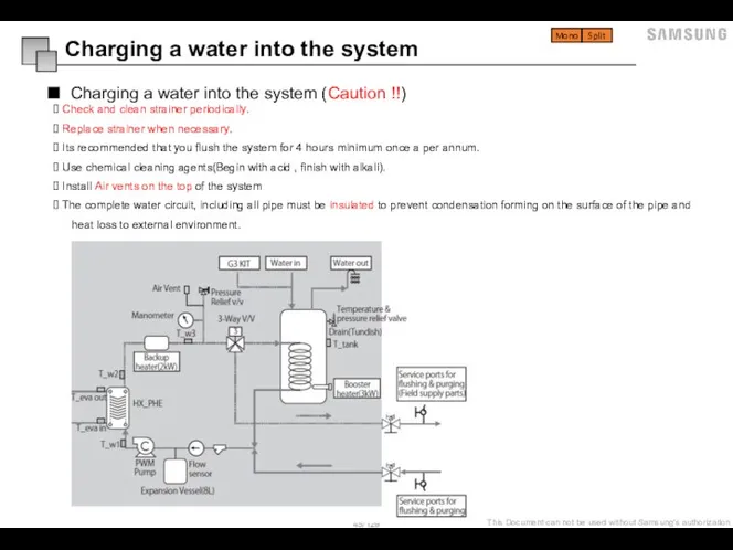
- 45. Charging a water into the system (Caution !!) Check and clean strainer periodically. Replace strainer when
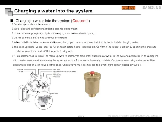
- 46. Charging a water into the system (Caution !!) Service space should be secured. Water pipe and
- 47. How to choose an expansion vessel When it is required to change the default pre-pressure of
- 48. How to choose a water pump The illustration below shows the external static pressure of the
- 49. Freeze protection Freeze protection solutions must use propylene glycol with a toxicity rating of Class 1
- 50. Split outdoor unit Installation information Wiring
- 51. Space requirements Installation information Mono Split TDM
- 52. Base and anchor bolts Installation information AE040/050/060RX**EG AE080/090/120/160RXYD*G Mono Split TDM
- 53. Drainage In case there is not enough space for drainage of the unit, additional drain works
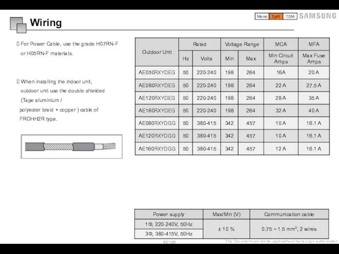
- 54. For Power Cable, use the grade H07RN-F or H05RN-F materials. When installing the indoor unit, outdoor
- 55. Mono outdoor unit Installation information Wiring
- 56. Drainage In case there is not enough space for drainage of the unit, additional drain works
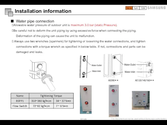
- 57. Water pipe connection Allowable water pressure of outdoor unit is maximum 3.0 bar (static Pressure). Be
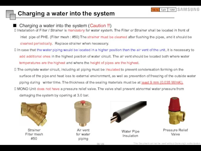
- 58. Charging a water into the system (Caution !!) Installation of Filter / Strainer is mandatory for
- 59. Flow Sensor Flow sensor is not an integrated part of ODU. But the installation is essential
- 60. Freeze protection Freeze protection solutions must use propylene glycol with a toxicity rating of Class 1
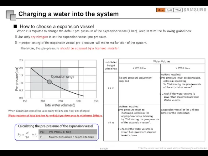
- 61. How to choose a expansion vessel When it is required to change the default pre-pressure of
- 62. For Power Cable, use the grade H07RN-F or H05RN-F materials. When installing the indoor unit, outdoor
- 63. External wiring and set up with Hydro unit, Control kit Board features Information of connecting terminal
- 64. Control box features Control kit control panel (Mono) Hydro unit control panel (Split/Mono) Mono Split TDM
- 65. Hydro unit / Control kit board Board features Mono Split TDM
- 66. Main board of Hydro unit & Control kit(mono) Board features Mono Split TDM
- 67. Information of connecting terminal block Main Power ELCB Mixing V/V Solar Pump Room thermostat1 Room thermostat2
- 68. External contact of Hydro unit and Control kit Booster heater (Inside of DHW tank) Sensor OD
- 69. Inverter water pump and PWM External contact of Hydro unit and Control kit PWM signal (Inverter
- 70. External contact information Additional pump (Fixed) ※ When connect multi water pump to 1 port, Magnet
- 71. External contact information Mixing valve ※ Hydro unit or Control kit power should be turned off
- 72. External contact information Mixing valve temperature sensor Mono Split TDM
- 73. External contact information Backup boiler ※ Control kit power should be turned off before the installation.
- 74. External contact information 2 way valves ※ When outlet water temperature reach to lower than 16
- 75. External contact information 3 way valve for DHW Mono Split TDM
- 76. External contact information Thermostats ※ Contact signal must be “L“. If you install two thermostats, thermostat2
- 77. External contact information Solar pump signal for DHW In operating mode, signal shall be around 230Vac
- 78. External contact information Peak Control (FSV 5041 = “1”) Mono Split TDM ※ Smart grid signal
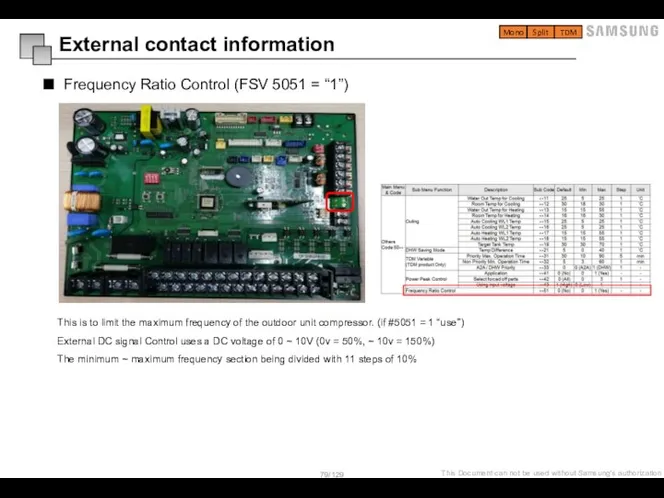
- 79. External contact information Frequency Ratio Control (FSV 5051 = “1”) Mono Split TDM This is to
- 80. Switches of unit Switch configuration (Outdoor unit / Hydro unit / Control kit) Hydro unit /
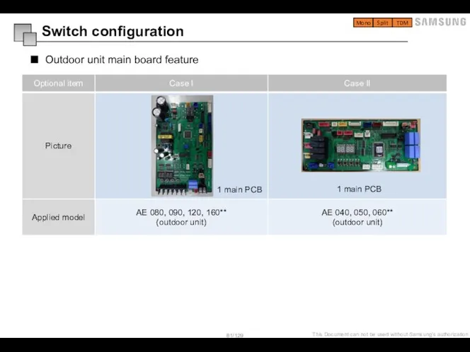
- 81. Outdoor unit main board feature Switch configuration Mono Split TDM 1 main PCB 1 main PCB
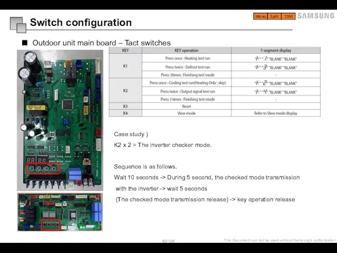
- 82. Outdoor unit main board – Tact switches Switch configuration Case study ) K2 x 2 =
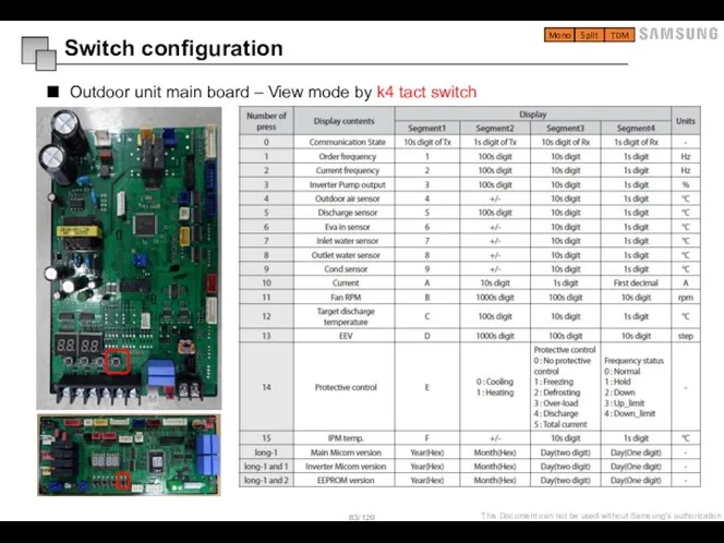
- 83. Switch configuration Outdoor unit main board – View mode by k4 tact switch Mono Split TDM
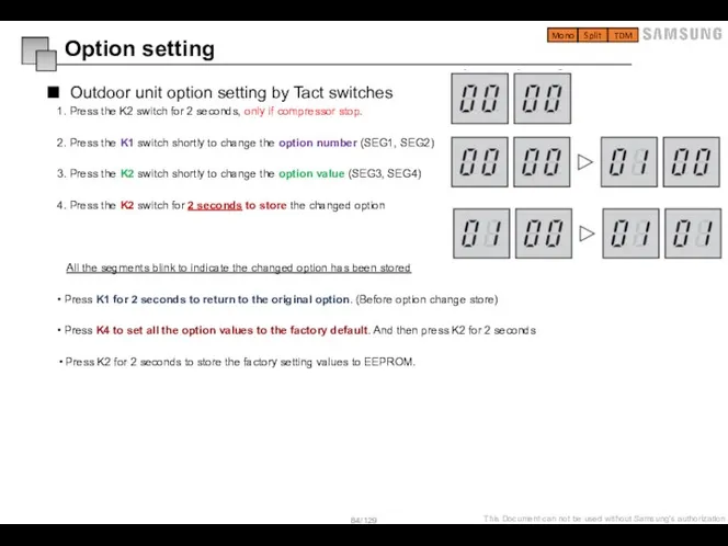
- 84. 1. Press the K2 switch for 2 seconds, only if compressor stop. 2. Press the K1
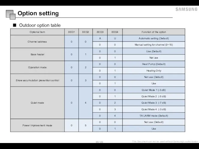
- 85. Outdoor option table Option setting
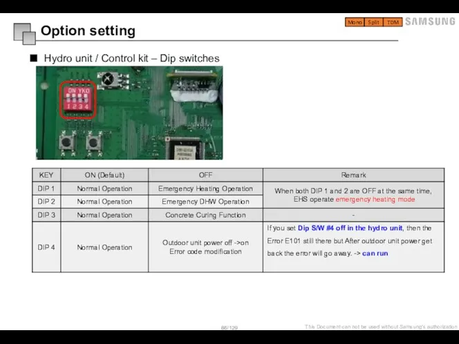
- 86. Hydro unit / Control kit – Dip switches Option setting Mono Split TDM
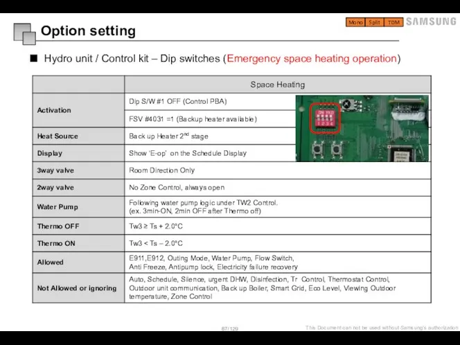
- 87. Hydro unit / Control kit – Dip switches (Emergency space heating operation) Option setting Mono Split
- 88. Hydro unit / Control kit – Dip switches (Emergency DHW operation) Option setting Mono Split TDM
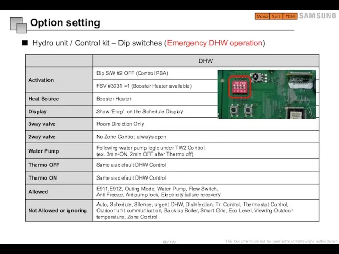
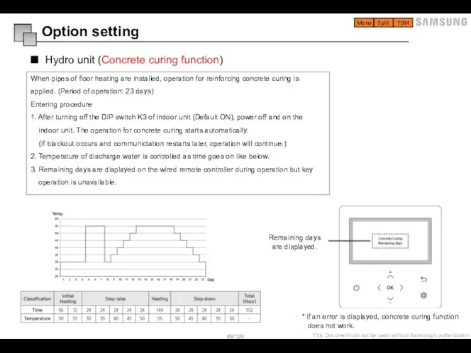
- 89. When pipes of floor heating are installed, operation for reinforcing concrete curing is applied. (Period of
- 90. Field Setting Value Service Mode Setting Field Setting Value
- 91. Remote controller Overview (MWR-WW00N) Service mode Setting Mono Split TDM 01 Operation status display - Displays
- 92. How to set the service mode with wired remote controller (MWR-WW00N) Service mode Setting Mono Split
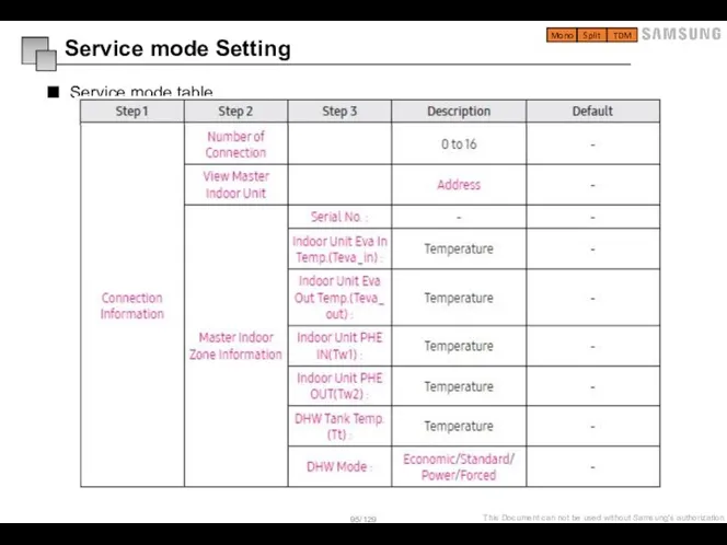
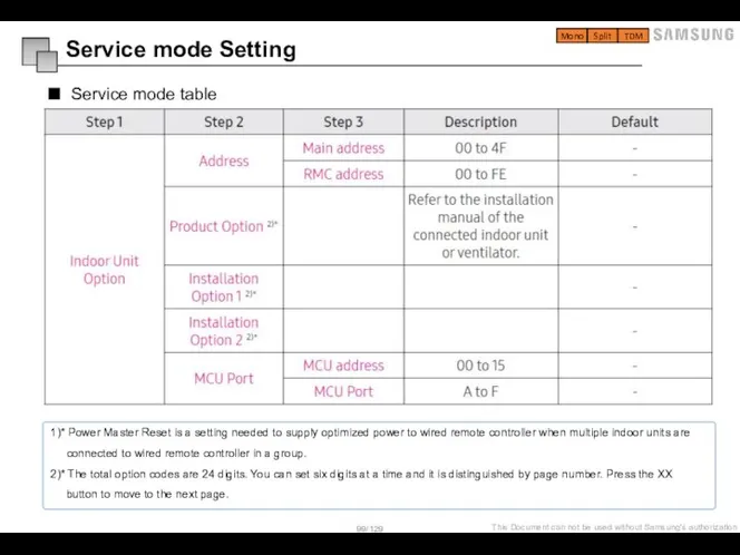
- 93. Service mode table Mono Split TDM Service mode Setting 1. Unavailable functions are marked inactive and
- 94. Service mode table Mono Split TDM Service mode Setting
- 95. Service mode table Mono Split TDM Service mode Setting
- 96. Service mode table Mono Split TDM Service mode Setting
- 97. Service mode table Mono Split TDM Service mode Setting
- 98. Service mode table Mono Split TDM Service mode Setting
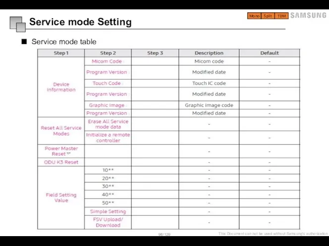
- 99. Service mode table Mono Split TDM Service mode Setting 1)* Power Master Reset is a setting
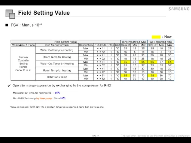
- 100. FSV : Menus 10** : New Operation range expansion by exchanging to the compressor for R-32
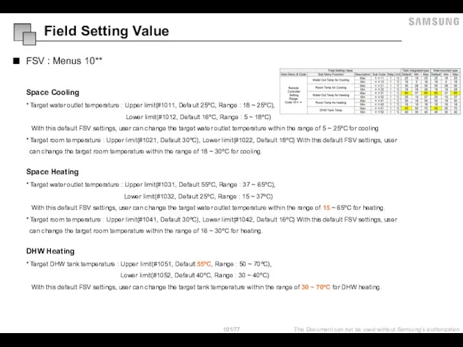
- 101. FSV : Menus 10** Space Cooling * Target water outlet temperature : Upper limit(#1011, Default 25ºC,
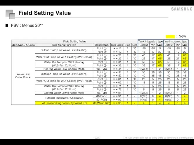
- 102. FSV : Menus 20** : New Field Setting Value
- 103. FSV : Menus 20** Water Law - This function is used by room sensor of wired
- 104. FSV : Menus 2091/2092 External Room Thermostat (Field Option) ( #2091 = 1, #2092 = 1
- 105. FSV : Menus 2093 Wired Remote Controller ( #2093 = 1 ) Judgment for “Thermo On”
- 106. FSV : Menus 30** : New Field Setting Value
- 107. FSV : Menus 302* / 303* - 302∗ : Heat pump variables for tank temp. control
- 108. FSV : Menus 302* / 303* - 302∗ : Heat pump variables for tank temp. control
- 109. FSV : Menus 304* - 304∗ : Periodical disinfection heating of water tank [ Time variation
- 110. FSV : Menus 30** - 305∗ : Forced DHW operation . FSV #3011, should be set
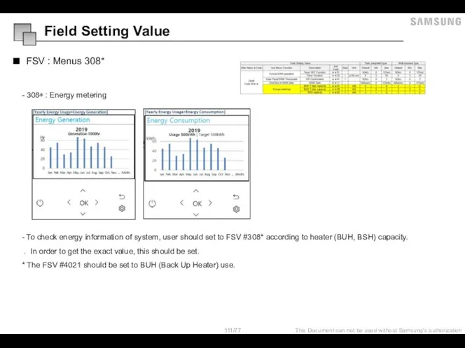
- 111. FSV : Menus 308* - 308∗ : Energy metering - To check energy information of system,
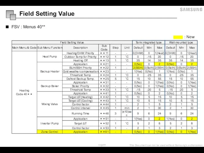
- 112. FSV : Menus 40** : New Field Setting Value
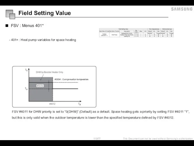
- 113. FSV : Menus 401* - 401∗ : Heat pump variables for space heating FSV #4011 for
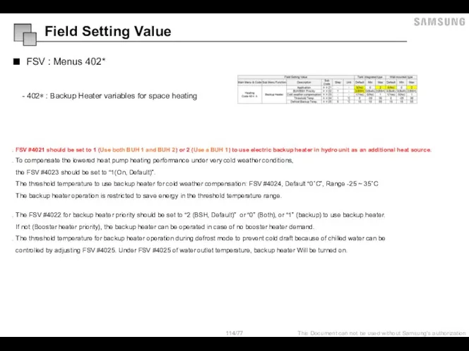
- 114. FSV : Menus 402* - 402∗ : Backup Heater variables for space heating . FSV #4021
- 115. FSV : Menus 403* - 403∗ : External Backup Boiler for space heating . FSV #4031
- 116. FSV : Menus 404* - 404∗ : Mixing valve installation ΔT(heat) = Tw3 - Tw4 .
- 117. FSV : Menus 405* - 405∗ : Inverter pump control The FSV #4051 should be set
- 118. FSV : Menus 4061 - 4061 : Zone control The FSV #4061 should be set to
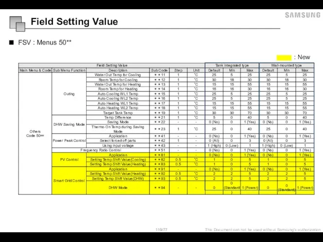
- 119. FSV : Menus 50** : New Field Setting Value
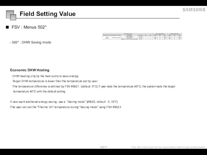
- 120. FSV : Menus 502* - 502* : DHW Saving mode Economic DHW Heating . DHW heating
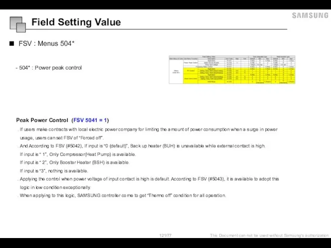
- 121. FSV : Menus 504* - 504* : Power peak control Peak Power Control (FSV 5041 =
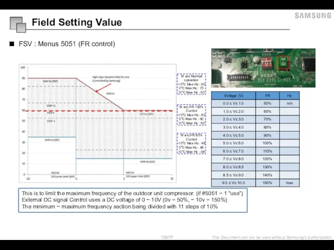
- 122. FSV : Menus 5051 (FR control) This is to limit the maximum frequency of the outdoor
- 123. FSV : Menus 508* - 508* : PV Control (Photovoltaics control) - This is for energy
- 124. FSV : Menus 509* Operation mode for Smart Grid 1) Mode 1 : Forced thermo off
- 125. FSV : Menus 50** 3) Mode 3 : When operating on, the setting temperature is reflected
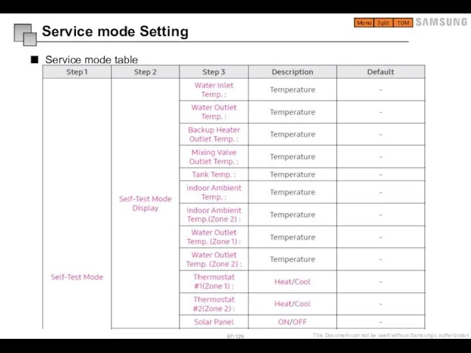
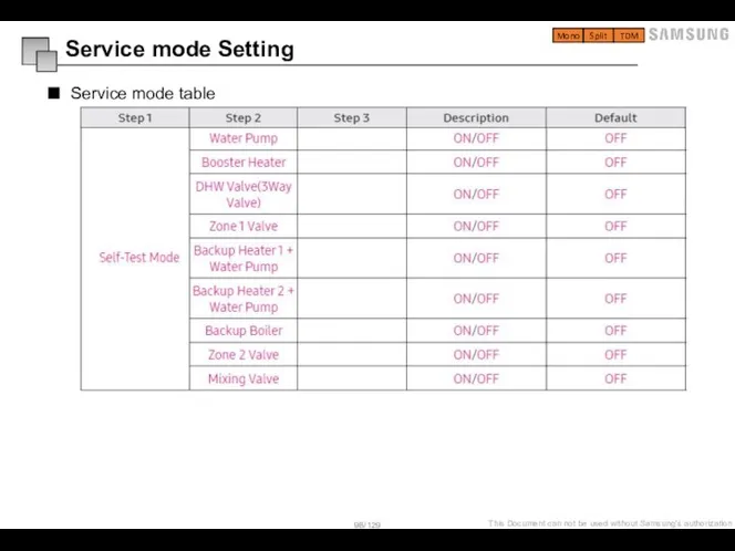
- 126. Special mode Self-Test mode - Enter the self-test mode using wired remote controller, * Load list
- 128. Скачать презентацию
Слайд 3Process and General installation guide
Tank Integrated Hydro unit
Split outdoor unit
Mono outdoor unit
External
Process and General installation guide
Tank Integrated Hydro unit
Split outdoor unit
Mono outdoor unit
External
Слайд 4Process
Before start
What is EHS
Nomenclature
Preparation of installation
General guide of pipe drawing
Installation tip
Required tool
Process
Before start
What is EHS
Nomenclature
Preparation of installation
General guide of pipe drawing
Installation tip
Required tool
Слайд 5Before start
▶ Read Installation Manual carefully to guarantee the proper installation
▶
Before start
▶ Read Installation Manual carefully to guarantee the proper installation
▶
Слайд 6What is EHS
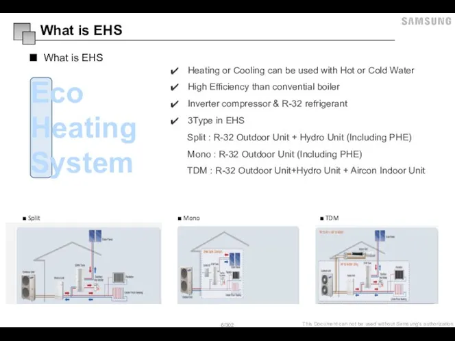
What is EHS
Heating or Cooling can be used with Hot
What is EHS
What is EHS
Heating or Cooling can be used with Hot
Слайд 7System Types – Tank Integrated Split
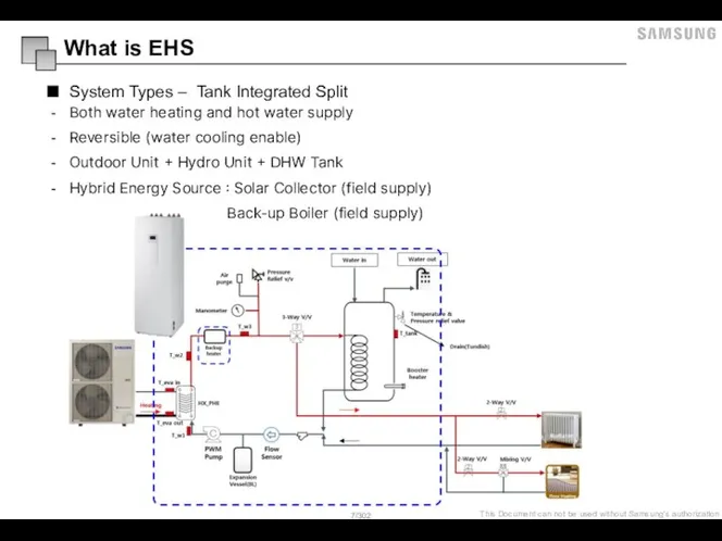
What is EHS
Both water heating and
System Types – Tank Integrated Split
What is EHS
Both water heating and
Слайд 8System Types – Tank Integrated Mono
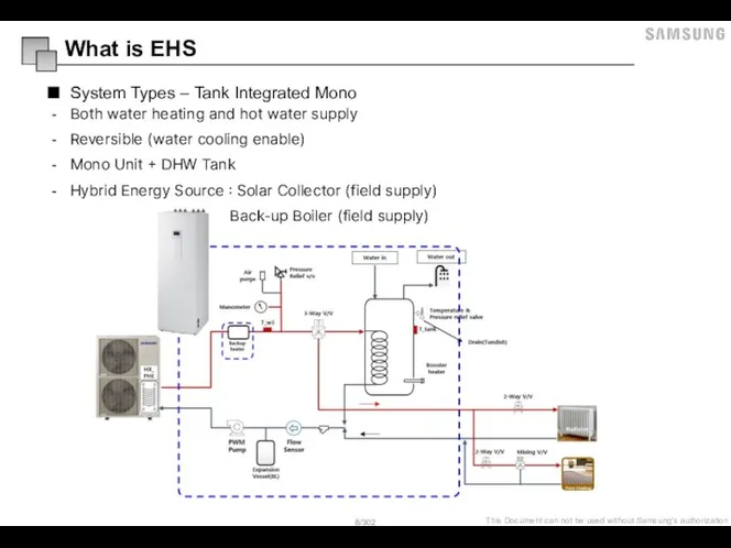
What is EHS
Both water heating and
System Types – Tank Integrated Mono
What is EHS
Both water heating and
Слайд 10Preparation of installation
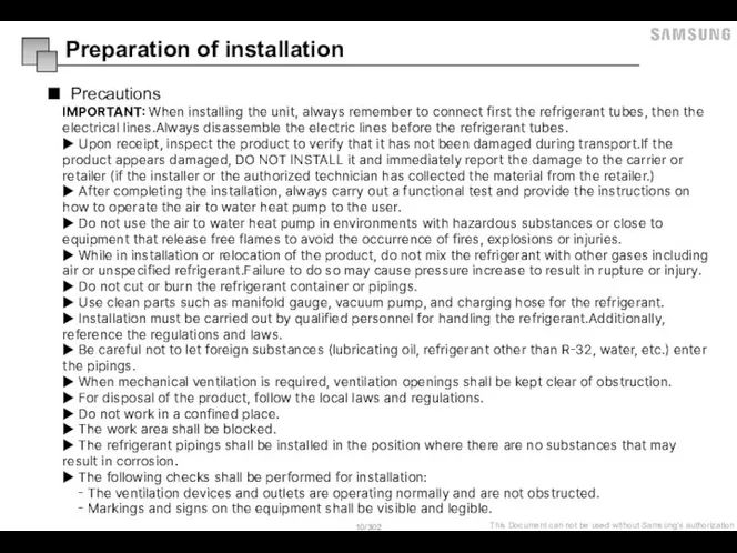
Precautions
IMPORTANT: When installing the unit, always remember to connect first
Preparation of installation
Precautions
IMPORTANT: When installing the unit, always remember to connect first
Слайд 11Preparation of installation
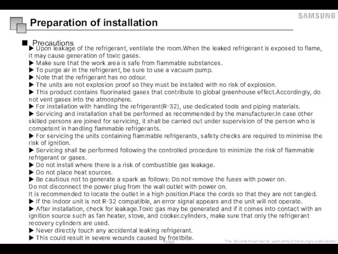
Precautions
▶ Upon leakage of the refrigerant, ventilate the room.When the
Preparation of installation
Precautions
▶ Upon leakage of the refrigerant, ventilate the room.When the
Слайд 12Indoor unit / Outdoor unit compatibility
Preparation of installation
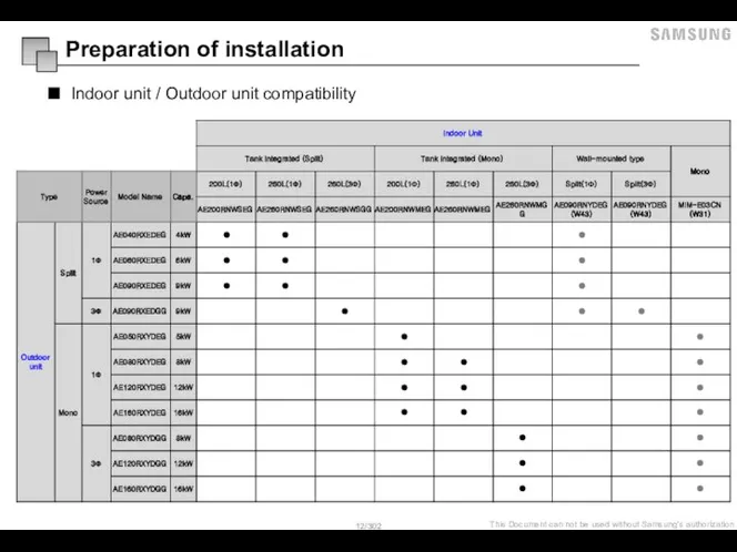
Indoor unit / Outdoor unit compatibility
Preparation of installation
Слайд 13Move the unit
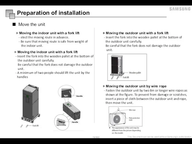
▷ Moving the indoor unit with a fork lift
-
Move the unit
▷ Moving the indoor unit with a fork lift
-
Слайд 14Pipe limitation – 4/6/9 kW 1 fan Split outdoor unit
General guide of
Pipe limitation – 4/6/9 kW 1 fan Split outdoor unit
General guide of
Слайд 15Additional refrigerant charging
[ SPLIT ]
Mono
Split
TDM
Additional refrigerant charging
[ SPLIT ]
Mono
Split
TDM
![Additional refrigerant charging [ SPLIT ] Mono Split TDM](/_ipx/f_webp&q_80&fit_contain&s_1440x1080/imagesDir/jpg/951622/slide-14.jpg)
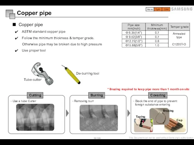
Слайд 16- Use a tube Cutter
ASTM standard copper pipe
Follow the minimum thickness &
ASTM standard copper pipe
Follow the minimum thickness &
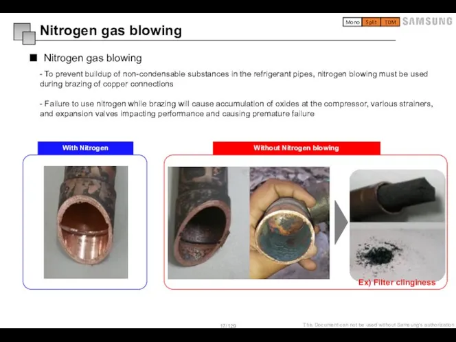
Слайд 17Nitrogen gas blowing
Nitrogen gas blowing
- To prevent buildup of non-condensable substances in
Nitrogen gas blowing
Nitrogen gas blowing
- To prevent buildup of non-condensable substances in
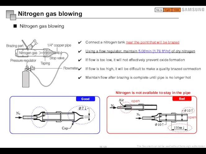
Слайд 18Nitrogen gas blowing
Nitrogen gas blowing
Good
Bad
open
open
Nitrogen is not available to stay in
Nitrogen gas blowing
Nitrogen gas blowing
Good
Bad
open
open
Nitrogen is not available to stay in
Слайд 19- Make sure that there are no foreign materials and impurities inside
- Make sure that there are no foreign materials and impurities inside
Слайд 201) Installing the hanger bolt(or others like ladder tray )
-
1) Installing the hanger bolt(or others like ladder tray )
-
Слайд 21Perform the air Tight Test to check leakage with Nitrogen gas
-
Perform the air Tight Test to check leakage with Nitrogen gas
-
Слайд 22※ Test Pressure
- R-32 : 46.9kgf/cm2 = 4.6Mpa = 667.2psi
1. Maintains 4.6MPa
※ Test Pressure
- R-32 : 46.9kgf/cm2 = 4.6Mpa = 667.2psi
1. Maintains 4.6MPa
Слайд 231) Insulate the refrigerant pipe based on the proper thickness of insulator
1) Insulate the refrigerant pipe based on the proper thickness of insulator
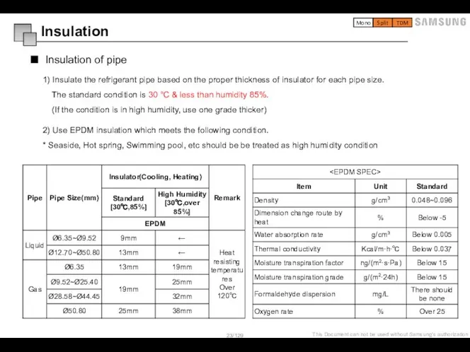
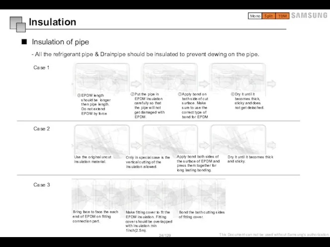
Слайд 24Put the pipe in EPDM insulation carefully so that the pipe will
Put the pipe in EPDM insulation carefully so that the pipe will
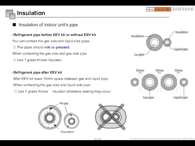
Слайд 25- Refrigerant pipe before EEV kit or without EEV kit
You
- Refrigerant pipe before EEV kit or without EEV kit
You
Слайд 26Wire pipe (tube)
Selection of wire and circuit breaker
Install the pipe (tube)
Wire pipe (tube)
Selection of wire and circuit breaker
Install the pipe (tube)
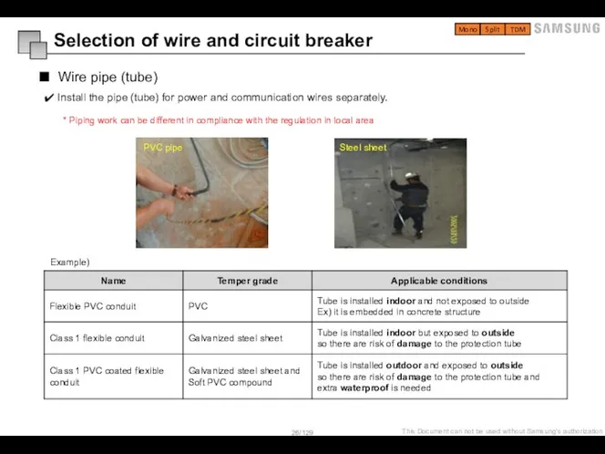
Слайд 27 - Select a solderless ring terminal for a power cable according
- Select a solderless ring terminal for a power cable according
Слайд 28Wire selection
Selection of wire and circuit breaker
Let your electrical engineer the MCA
Wire selection
Selection of wire and circuit breaker
Let your electrical engineer the MCA
Слайд 29Address can be check(set) easily by following the step
Step 1. Print attached
Address can be check(set) easily by following the step
Step 1. Print attached
Слайд 30Required tool
Tube cutter & de-burring tool
Hands tools
Manifold Set (dedicated for R-32)
Flaring Tool
Required tool
Tube cutter & de-burring tool
Hands tools
Manifold Set (dedicated for R-32)
Flaring Tool
Слайд 31Tank intergrated Hydro unit
Example of application
Installation information
Mounting the Hydro unit
Charging a water
Tank intergrated Hydro unit
Example of application
Installation information
Mounting the Hydro unit
Charging a water
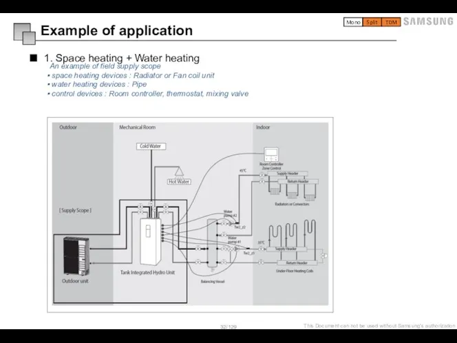
Слайд 321. Space heating + Water heating
Example of application
An example of field supply
1. Space heating + Water heating
Example of application
An example of field supply
Слайд 332. Hybrid application (Back-up boiler and solar panel connected)
Example of application
Mono
Split
TDM
An example
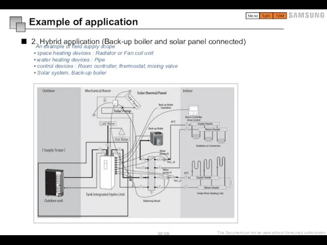
2. Hybrid application (Back-up boiler and solar panel connected)
Example of application
Mono
Split
TDM
An example
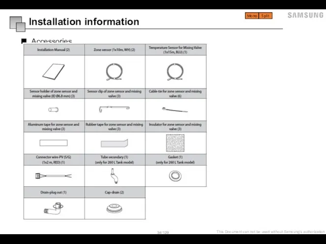
Слайд 34Accessories
Installation information
Mono
Split
Accessories
Installation information
Mono
Split
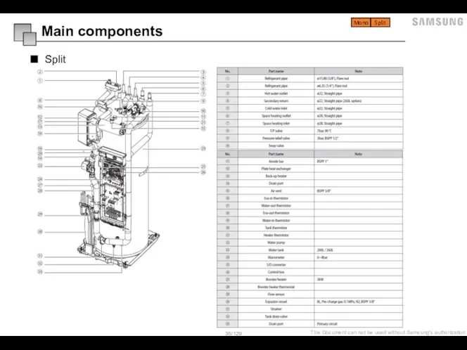
Слайд 35Split
Main components
Mono
Split
Split
Main components
Mono
Split
Слайд 36Mono
Mono
Split
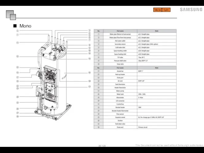
Mono
Mono
Split
Слайд 37Dimensional drawing of Hydro unit
Installation information
Mono
Split
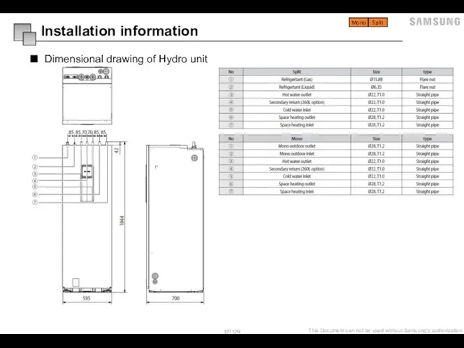
Dimensional drawing of Hydro unit
Installation information
Mono
Split
Слайд 38Installation of the Indoor unit
Installation information
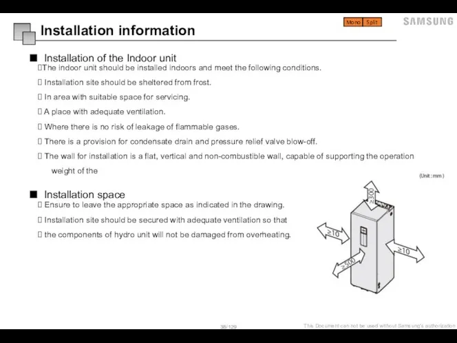
The indoor unit should be installed indoors
Installation of the Indoor unit
Installation information
The indoor unit should be installed indoors
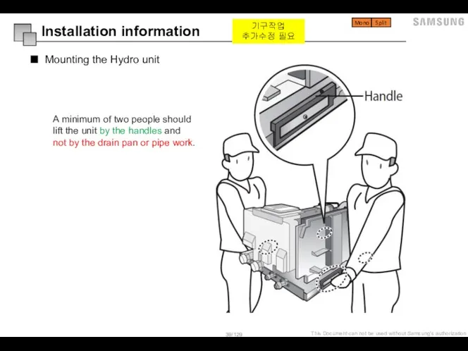
Слайд 39Mounting the Hydro unit
Installation information
A minimum of two people should
lift the unit
Mounting the Hydro unit
Installation information
A minimum of two people should
lift the unit
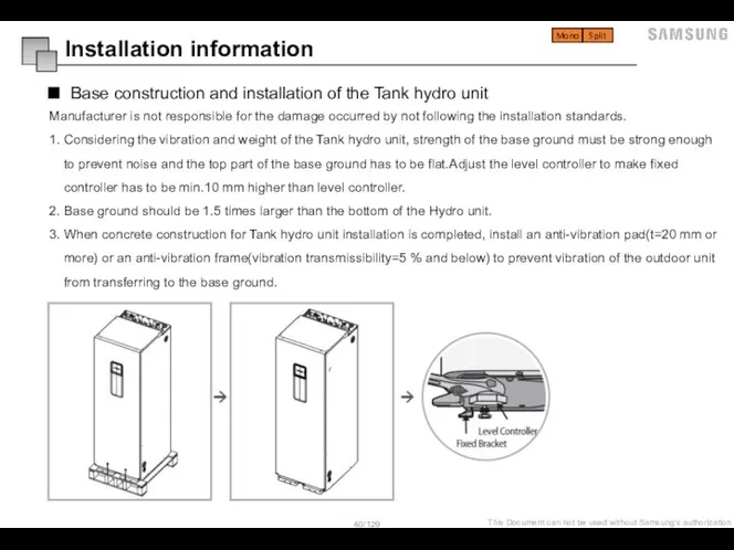
Слайд 40Base construction and installation of the Tank hydro unit
Installation information
Manufacturer is
Base construction and installation of the Tank hydro unit
Installation information
Manufacturer is
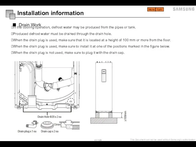
Слайд 41Drain Work
Installation information
In the cooling operation, defrost water may be produced from
Drain Work
Installation information
In the cooling operation, defrost water may be produced from
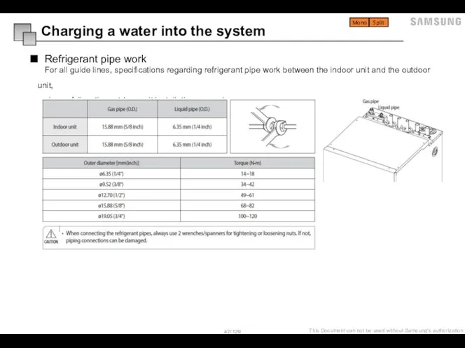
Слайд 42Refrigerant pipe work
Charging a water into the system
For all guide lines,
Refrigerant pipe work
Charging a water into the system
For all guide lines,
Слайд 43Water pipe work
Charging a water into the system
The hydro unit is equipped
Water pipe work
Charging a water into the system
The hydro unit is equipped
Слайд 44Charging a water into the system
When filling water, the following start-up procedure
Charging a water into the system
When filling water, the following start-up procedure
Слайд 45Charging a water into the system (Caution !!)
Check and clean strainer
Charging a water into the system (Caution !!)
Check and clean strainer
Слайд 46Charging a water into the system (Caution !!)
Service space should be
Charging a water into the system (Caution !!)
Service space should be
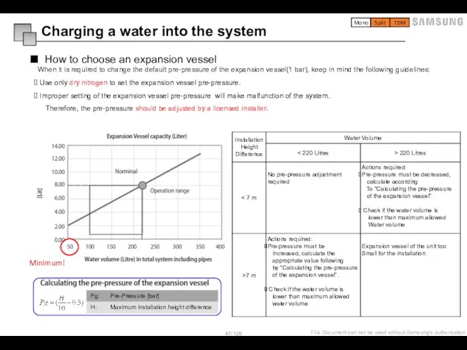
Слайд 47How to choose an expansion vessel
When it is required to change the
How to choose an expansion vessel
When it is required to change the
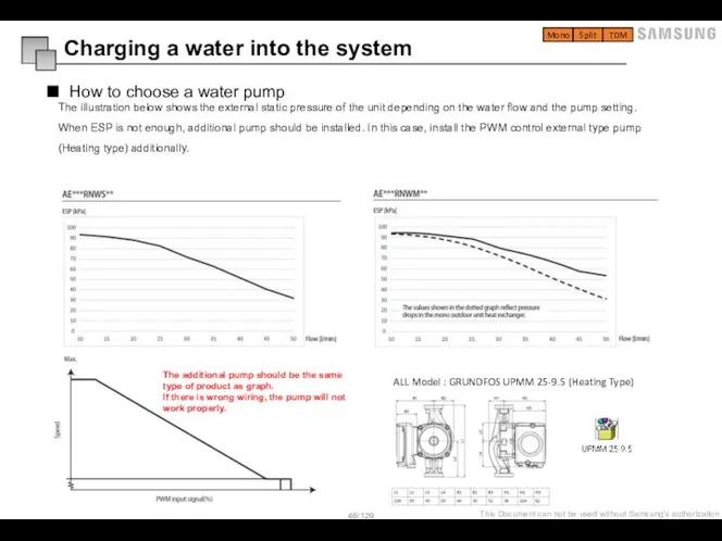
Слайд 48How to choose a water pump
The illustration below shows the external static
How to choose a water pump
The illustration below shows the external static
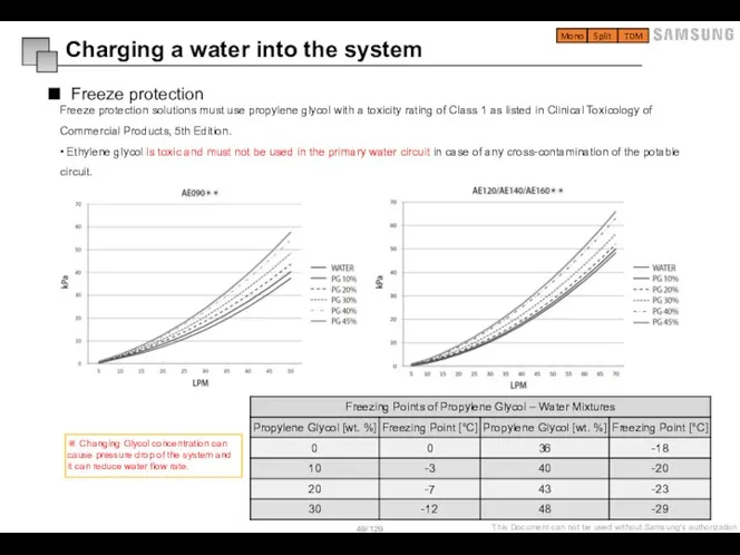
Слайд 49Freeze protection
Freeze protection solutions must use propylene glycol with a toxicity rating
Freeze protection
Freeze protection solutions must use propylene glycol with a toxicity rating
Слайд 50Split outdoor unit
Installation information
Wiring
Split outdoor unit
Installation information
Wiring
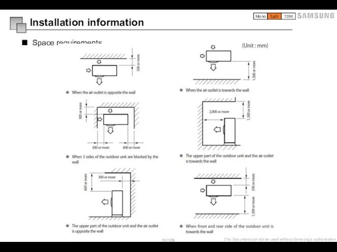
Слайд 51Space requirements
Installation information
Mono
Split
TDM
Space requirements
Installation information
Mono
Split
TDM
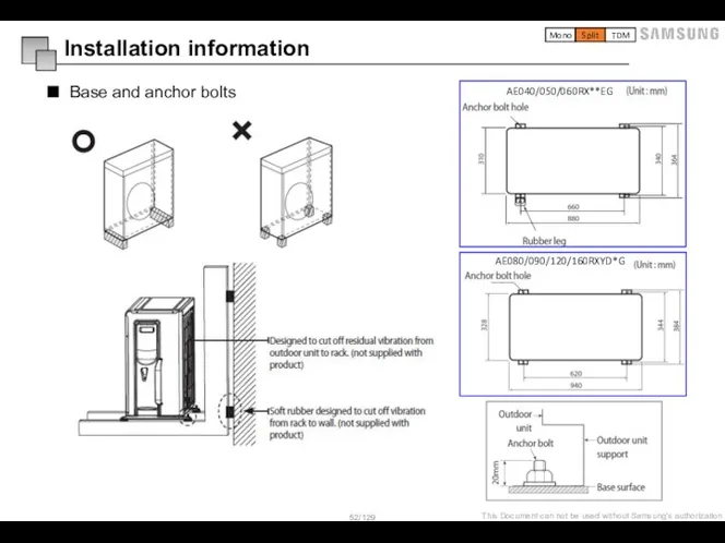
Слайд 52Base and anchor bolts
Installation information
AE040/050/060RX**EG
AE080/090/120/160RXYD*G
Mono
Split
TDM
Base and anchor bolts
Installation information
AE040/050/060RX**EG
AE080/090/120/160RXYD*G
Mono
Split
TDM
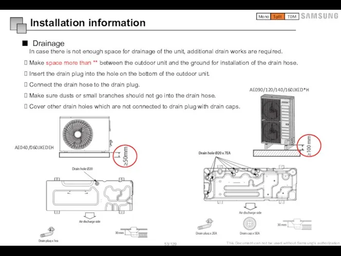
Слайд 53Drainage
In case there is not enough space for drainage of the
Drainage
In case there is not enough space for drainage of the
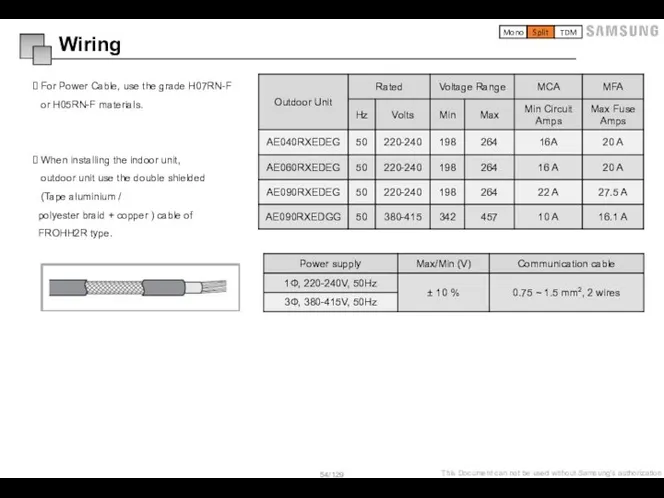
Слайд 54 For Power Cable, use the grade H07RN-F
or H05RN-F materials.
When installing
For Power Cable, use the grade H07RN-F
or H05RN-F materials.
When installing
Слайд 55Mono outdoor unit
Installation information
Wiring
Mono outdoor unit
Installation information
Wiring
Слайд 56Drainage
In case there is not enough space for drainage of the
Drainage
In case there is not enough space for drainage of the

Слайд 57Water pipe connection
Allowable water pressure of outdoor unit is maximum 3.0 bar
Water pipe connection
Allowable water pressure of outdoor unit is maximum 3.0 bar
Слайд 58Charging a water into the system (Caution !!)
Installation of Filter /
Charging a water into the system (Caution !!)
Installation of Filter /
Слайд 59Flow Sensor
Flow sensor is not an integrated part of ODU. But
Flow Sensor
Flow sensor is not an integrated part of ODU. But

Слайд 60Freeze protection
Freeze protection solutions must use propylene glycol with a toxicity rating
Freeze protection
Freeze protection solutions must use propylene glycol with a toxicity rating

Слайд 61How to choose a expansion vessel
When it is required to change the
How to choose a expansion vessel
When it is required to change the
Слайд 62 For Power Cable, use the grade H07RN-F
or H05RN-F materials.
When installing
For Power Cable, use the grade H07RN-F
or H05RN-F materials.
When installing
Слайд 63External wiring and set up with
Hydro unit, Control kit
Board features
Information of
External wiring and set up with
Hydro unit, Control kit
Board features
Information of
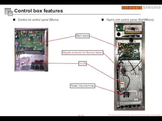
Слайд 64Control box features
Control kit control panel (Mono)
Hydro unit control panel (Split/Mono)
Mono
Split
TDM
Control box features
Control kit control panel (Mono)
Hydro unit control panel (Split/Mono)
Mono
Split
TDM
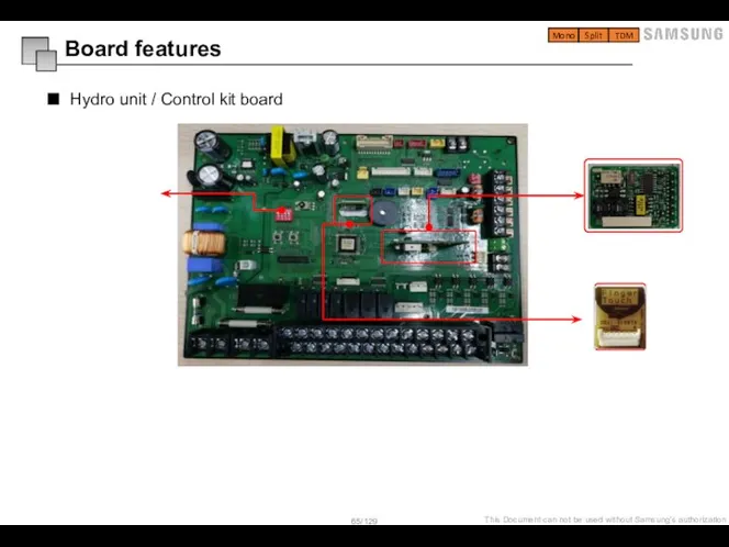
Слайд 65Hydro unit / Control kit board
Board features
Mono
Split
TDM
Hydro unit / Control kit board
Board features
Mono
Split
TDM
Слайд 66Main board of Hydro unit & Control kit(mono)
Board features
Mono
Split
TDM
Main board of Hydro unit & Control kit(mono)
Board features
Mono
Split
TDM
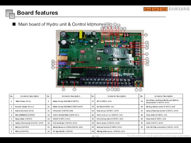
Слайд 67Information of connecting terminal block
Main Power
ELCB
Mixing V/V
Solar Pump
Room
thermostat1
Room
thermostat2
3way V/V
(DHW)
2way V/V
(Zone#2)
FCU
2way V/V
(Zone#1)
UFH
Additional
Water
Pump
Water
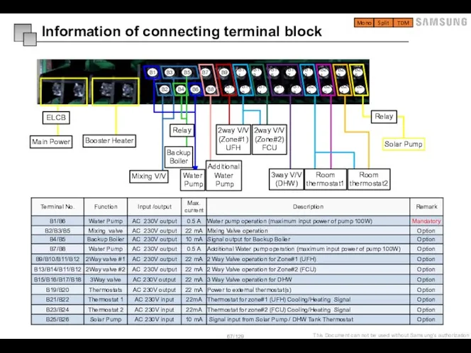
Information of connecting terminal block
Main Power
ELCB
Mixing V/V
Solar Pump
Room
thermostat1
Room
thermostat2
3way V/V
(DHW)
2way V/V
(Zone#2)
FCU
2way V/V
(Zone#1)
UFH
Additional
Water
Pump
Water
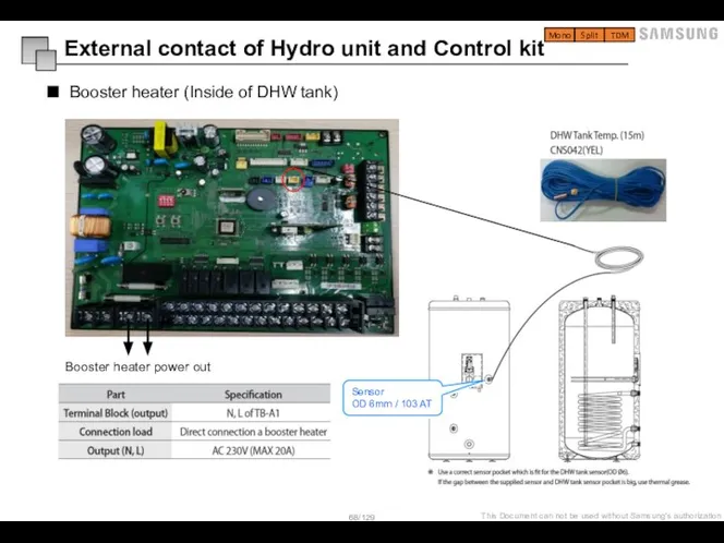
Слайд 68External contact of Hydro unit and Control kit
Booster heater (Inside of
External contact of Hydro unit and Control kit
Booster heater (Inside of
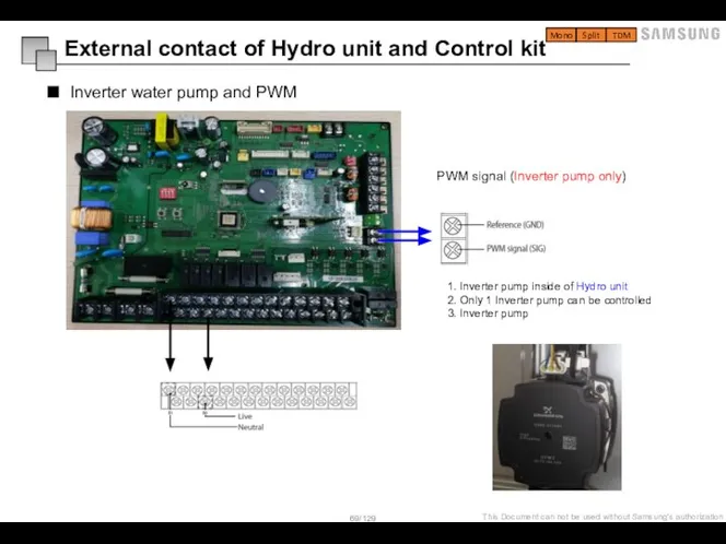
Слайд 69Inverter water pump and PWM
External contact of Hydro unit and Control
Inverter water pump and PWM
External contact of Hydro unit and Control
Слайд 70External contact information
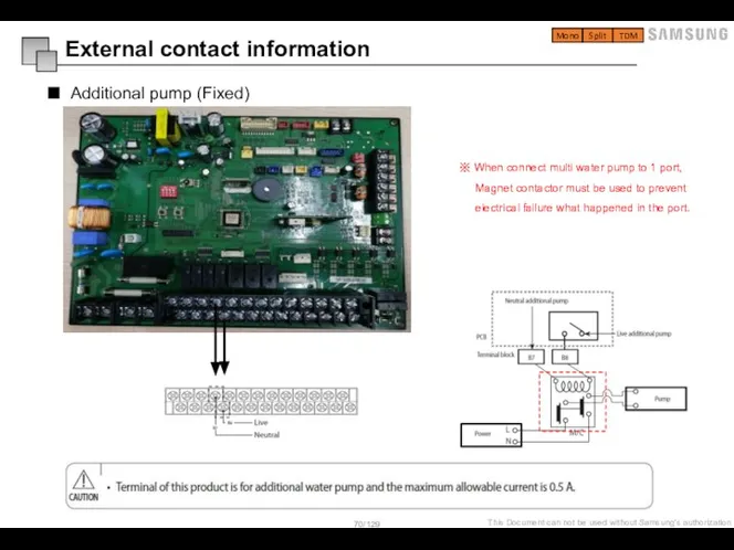
Additional pump (Fixed)
※ When connect multi water pump to 1
External contact information
Additional pump (Fixed)
※ When connect multi water pump to 1
Слайд 71External contact information
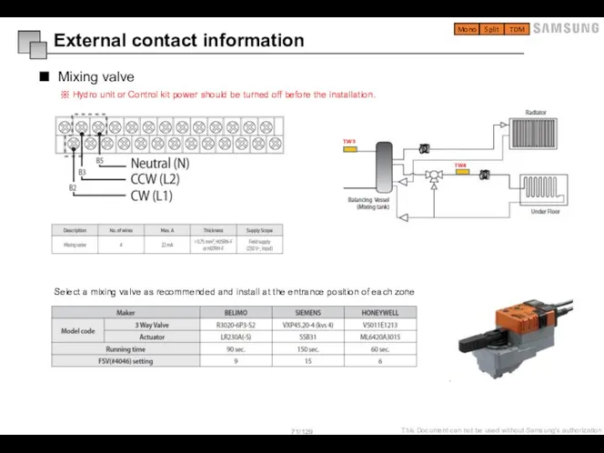
Mixing valve
※ Hydro unit or Control kit power should be
External contact information
Mixing valve
※ Hydro unit or Control kit power should be
Слайд 72External contact information
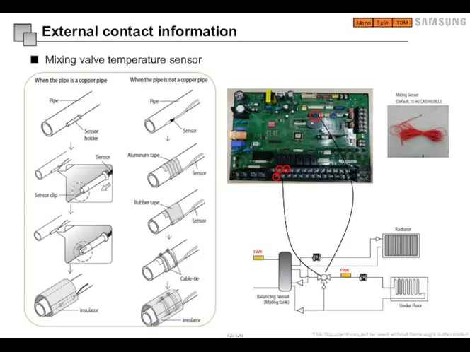
Mixing valve temperature sensor
Mono
Split
TDM
External contact information
Mixing valve temperature sensor
Mono
Split
TDM
Слайд 73External contact information
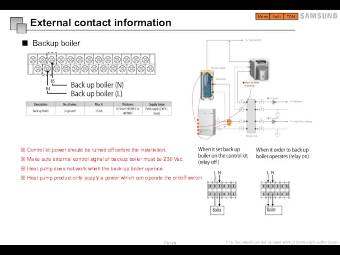
Backup boiler
※ Control kit power should be turned off before
External contact information
Backup boiler
※ Control kit power should be turned off before
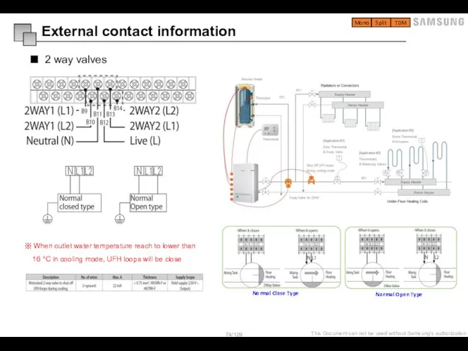
Слайд 74External contact information
2 way valves
※ When outlet water temperature reach to lower
External contact information
2 way valves
※ When outlet water temperature reach to lower
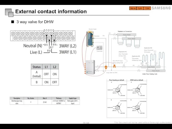
Слайд 75External contact information
3 way valve for DHW
Mono
Split
TDM
External contact information
3 way valve for DHW
Mono
Split
TDM
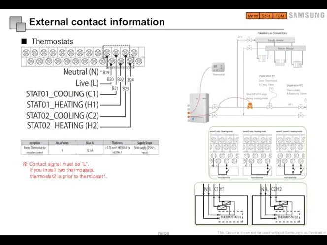
Слайд 76External contact information
Thermostats
※ Contact signal must be “L“.
If you install
External contact information
Thermostats
※ Contact signal must be “L“.
If you install
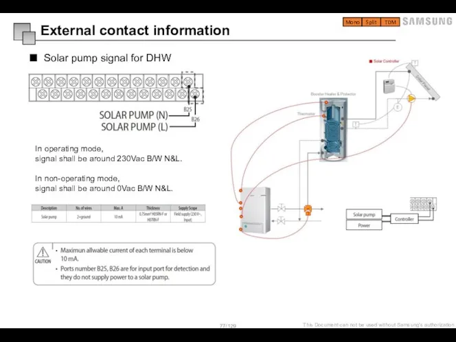
Слайд 77External contact information
Solar pump signal for DHW
In operating mode, signal shall be
External contact information
Solar pump signal for DHW
In operating mode, signal shall be
Слайд 78External contact information
Peak Control (FSV 5041 = “1”)
Mono
Split
TDM
※ Smart grid signal input
External contact information
Peak Control (FSV 5041 = “1”)
Mono
Split
TDM
※ Smart grid signal input

Слайд 79External contact information
Frequency Ratio Control (FSV 5051 = “1”)
Mono
Split
TDM
This is to limit
External contact information
Frequency Ratio Control (FSV 5051 = “1”)
Mono
Split
TDM
This is to limit
Слайд 80Switches of unit
Switch configuration (Outdoor unit / Hydro unit / Control kit)
Hydro
Switches of unit
Switch configuration (Outdoor unit / Hydro unit / Control kit)
Hydro
Слайд 81Outdoor unit main board feature
Switch configuration
Mono
Split
TDM
1 main PCB
1 main PCB
Outdoor unit main board feature
Switch configuration
Mono
Split
TDM
1 main PCB
1 main PCB
Слайд 82Outdoor unit main board – Tact switches
Switch configuration
Case study )
K2 x
Outdoor unit main board – Tact switches
Switch configuration
Case study )
K2 x
Слайд 83Switch configuration
Outdoor unit main board – View mode by k4 tact switch
Mono
Split
TDM
Switch configuration
Outdoor unit main board – View mode by k4 tact switch
Mono
Split
TDM
Слайд 841. Press the K2 switch for 2 seconds, only if compressor stop.
2.
1. Press the K2 switch for 2 seconds, only if compressor stop.
2.
Слайд 85Outdoor option table
Option setting
Outdoor option table
Option setting
Слайд 86Hydro unit / Control kit – Dip switches
Option setting
Mono
Split
TDM
Hydro unit / Control kit – Dip switches
Option setting
Mono
Split
TDM
Слайд 87Hydro unit / Control kit – Dip switches (Emergency space heating operation)
Option
Hydro unit / Control kit – Dip switches (Emergency space heating operation)
Option
Слайд 88Hydro unit / Control kit – Dip switches (Emergency DHW operation)
Option setting
Mono
Split
TDM
Hydro unit / Control kit – Dip switches (Emergency DHW operation)
Option setting
Mono
Split
TDM
Слайд 89When pipes of floor heating are installed, operation for reinforcing concrete curing
When pipes of floor heating are installed, operation for reinforcing concrete curing
Слайд 90Field Setting Value
Service Mode Setting
Field Setting Value
Field Setting Value
Service Mode Setting
Field Setting Value
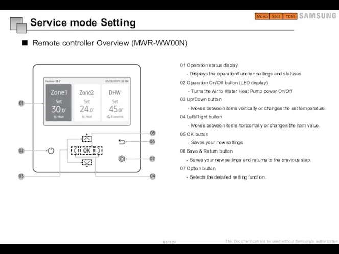
Слайд 91Remote controller Overview (MWR-WW00N)
Service mode Setting
Mono
Split
TDM
01 Operation status display
- Displays the
Remote controller Overview (MWR-WW00N)
Service mode Setting
Mono
Split
TDM
01 Operation status display
- Displays the
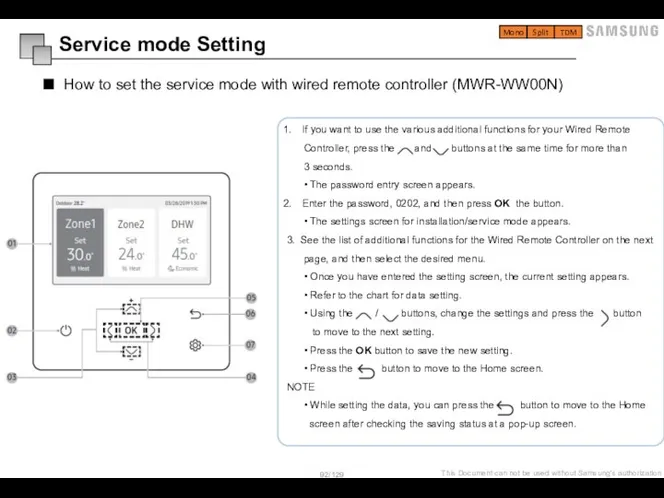
Слайд 92How to set the service mode with wired remote controller (MWR-WW00N)
Service mode
How to set the service mode with wired remote controller (MWR-WW00N)
Service mode
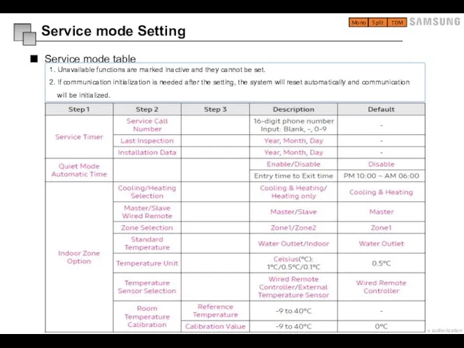
Слайд 93Service mode table
Mono
Split
TDM
Service mode Setting
1. Unavailable functions are marked inactive and they
Service mode table
Mono
Split
TDM
Service mode Setting
1. Unavailable functions are marked inactive and they
Слайд 94Service mode table
Mono
Split
TDM
Service mode Setting
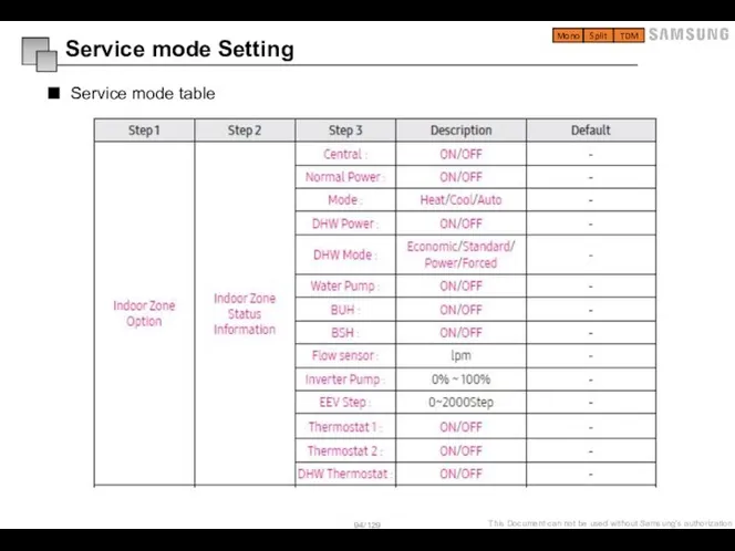
Service mode table
Mono
Split
TDM
Service mode Setting
Слайд 95Service mode table
Mono
Split
TDM
Service mode Setting
Service mode table
Mono
Split
TDM
Service mode Setting
Слайд 96Service mode table
Mono
Split
TDM
Service mode Setting
Service mode table
Mono
Split
TDM
Service mode Setting
Слайд 97Service mode table
Mono
Split
TDM
Service mode Setting
Service mode table
Mono
Split
TDM
Service mode Setting
Слайд 98Service mode table
Mono
Split
TDM
Service mode Setting
Service mode table
Mono
Split
TDM
Service mode Setting
Слайд 99Service mode table
Mono
Split
TDM
Service mode Setting
1)* Power Master Reset is a setting needed
Service mode table
Mono
Split
TDM
Service mode Setting
1)* Power Master Reset is a setting needed
Слайд 100FSV : Menus 10**
: New
Operation range expansion by exchanging to the compressor
FSV : Menus 10**
: New
Operation range expansion by exchanging to the compressor
Слайд 101FSV : Menus 10**
Space Cooling
* Target water outlet temperature : Upper
FSV : Menus 10**
Space Cooling
* Target water outlet temperature : Upper
Слайд 102FSV : Menus 20**
: New
Field Setting Value
FSV : Menus 20**
: New
Field Setting Value
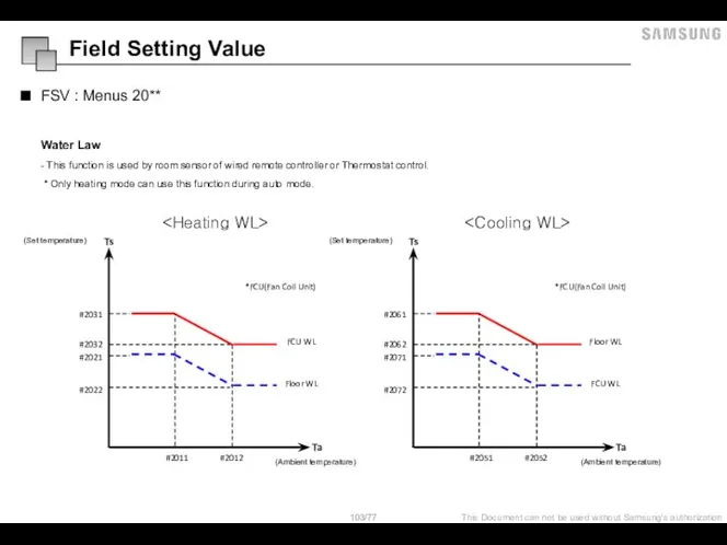
Слайд 103FSV : Menus 20**
Water Law
- This function is used by room
FSV : Menus 20**
Water Law
- This function is used by room
Слайд 104FSV : Menus 2091/2092
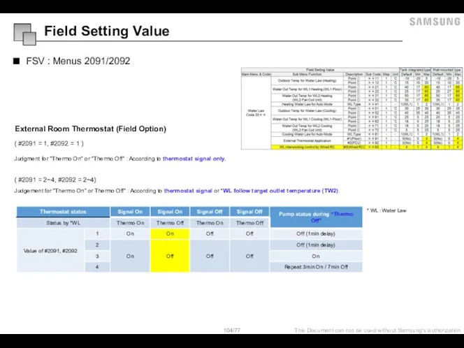
External Room Thermostat (Field Option)
( #2091 = 1, #2092
FSV : Menus 2091/2092
External Room Thermostat (Field Option)
( #2091 = 1, #2092
Слайд 105FSV : Menus 2093
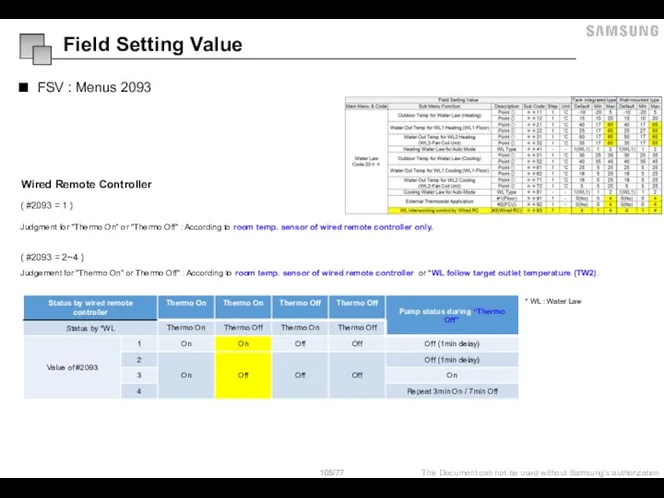
Wired Remote Controller
( #2093 = 1 )
Judgment for
FSV : Menus 2093
Wired Remote Controller
( #2093 = 1 )
Judgment for
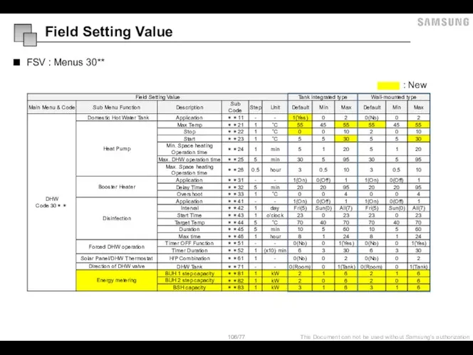
Слайд 106FSV : Menus 30**
: New
Field Setting Value
FSV : Menus 30**
: New
Field Setting Value
Слайд 107FSV : Menus 302* / 303*
- 302∗ : Heat pump variables for
FSV : Menus 302* / 303*
- 302∗ : Heat pump variables for
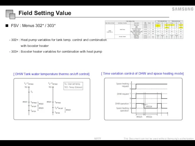
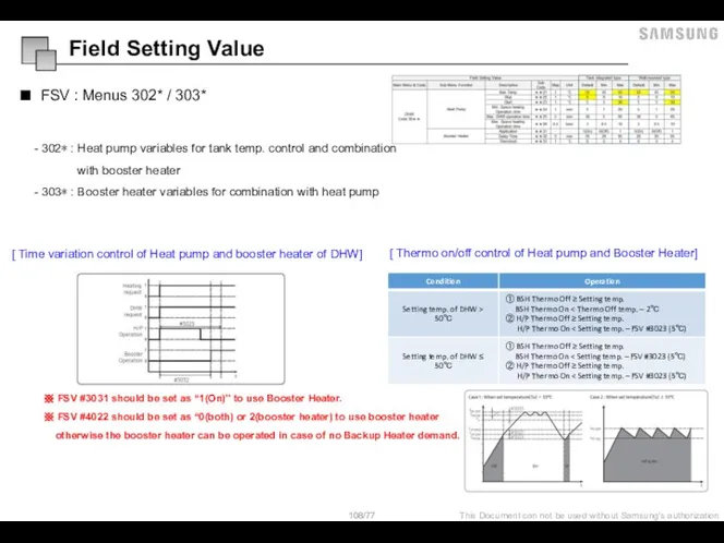
Слайд 108FSV : Menus 302* / 303*
- 302∗ : Heat pump variables for
FSV : Menus 302* / 303*
- 302∗ : Heat pump variables for
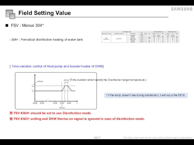
Слайд 109FSV : Menus 304*
- 304∗ : Periodical disinfection heating of water tank
FSV : Menus 304*
- 304∗ : Periodical disinfection heating of water tank
Слайд 110FSV : Menus 30**
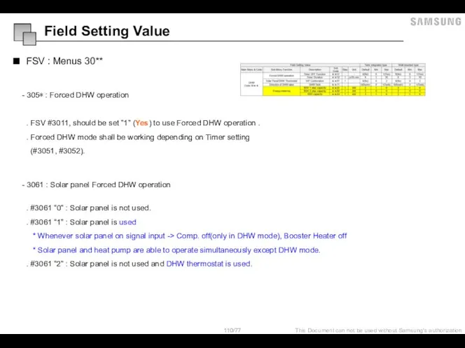
- 305∗ : Forced DHW operation
. FSV #3011,
FSV : Menus 30**
- 305∗ : Forced DHW operation
. FSV #3011,
Слайд 111FSV : Menus 308*
- 308∗ : Energy metering
- To check energy
FSV : Menus 308*
- 308∗ : Energy metering
- To check energy
Слайд 112FSV : Menus 40**
: New
Field Setting Value
FSV : Menus 40**
: New
Field Setting Value
Слайд 113FSV : Menus 401*
- 401∗ : Heat pump variables for space heating
FSV
FSV : Menus 401*
- 401∗ : Heat pump variables for space heating
FSV
Слайд 114FSV : Menus 402*
- 402∗ : Backup Heater variables for space heating
.
FSV : Menus 402*
- 402∗ : Backup Heater variables for space heating
.
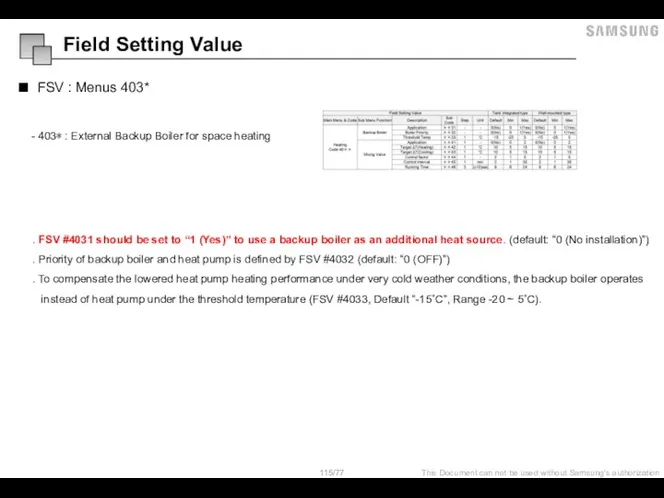
Слайд 115FSV : Menus 403*
- 403∗ : External Backup Boiler for space heating
.
FSV : Menus 403*
- 403∗ : External Backup Boiler for space heating
.
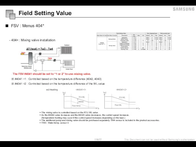
Слайд 116FSV : Menus 404*
- 404∗ : Mixing valve installation
ΔT(heat) = Tw3 -
FSV : Menus 404*
- 404∗ : Mixing valve installation
ΔT(heat) = Tw3 -
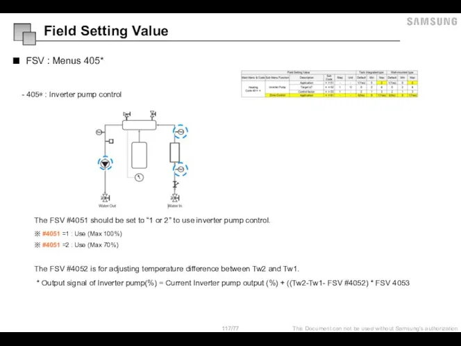
Слайд 117FSV : Menus 405*
- 405∗ : Inverter pump control
The FSV #4051 should
FSV : Menus 405*
- 405∗ : Inverter pump control
The FSV #4051 should
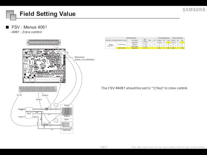
Слайд 118FSV : Menus 4061
- 4061 : Zone control
The FSV #4061 should be
FSV : Menus 4061
- 4061 : Zone control
The FSV #4061 should be
Слайд 119FSV : Menus 50**
: New
Field Setting Value
FSV : Menus 50**
: New
Field Setting Value
Слайд 120FSV : Menus 502*
- 502* : DHW Saving mode
Economic DHW Heating
FSV : Menus 502*
- 502* : DHW Saving mode
Economic DHW Heating
Слайд 121FSV : Menus 504*
- 504* : Power peak control
Peak Power Control (FSV
FSV : Menus 504*
- 504* : Power peak control
Peak Power Control (FSV
Слайд 122FSV : Menus 5051 (FR control)
This is to limit the maximum frequency
FSV : Menus 5051 (FR control)
This is to limit the maximum frequency
Слайд 123FSV : Menus 508*
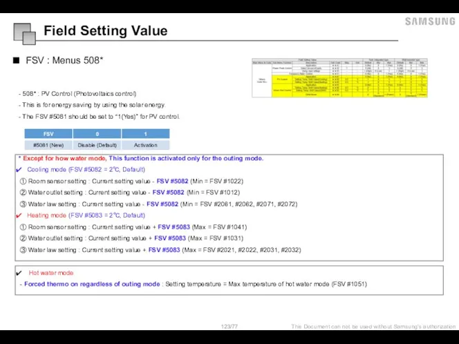
- 508* : PV Control (Photovoltaics control)
- This
FSV : Menus 508*
- 508* : PV Control (Photovoltaics control)
- This
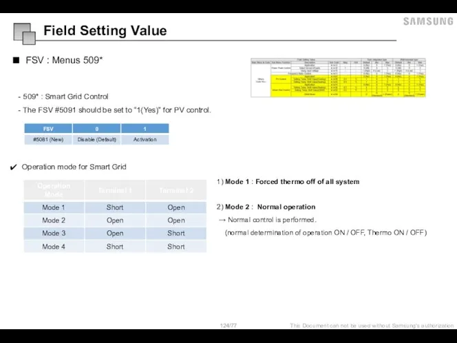
Слайд 124FSV : Menus 509*
Operation mode for Smart Grid
1) Mode 1 : Forced
FSV : Menus 509*
Operation mode for Smart Grid
1) Mode 1 : Forced
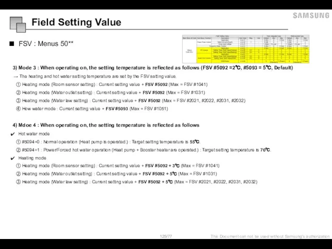
Слайд 125FSV : Menus 50**
3) Mode 3 : When operating on, the setting
FSV : Menus 50**
3) Mode 3 : When operating on, the setting
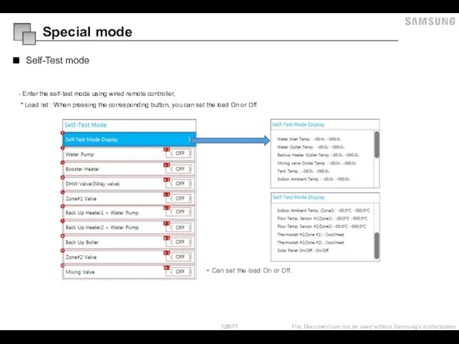
Слайд 126Special mode
Self-Test mode
- Enter the self-test mode using wired remote controller,
Special mode
Self-Test mode
- Enter the self-test mode using wired remote controller,
 Древняя Греция. Греко-персидские войны
 Решение спорных вопросов при перевозке грузов. Особенности ответственности перевозчиков. Макаров Антон МЭ 091 (ДС 01)
 Пасхальные яйца своими руками
 Игра по литературе
 Путь к успеху
 Презентация на тему Опустынивание
  Тайм-менеджмент
 15 июня - Всемирный день ветра
 HusqvarnaСтенорезные иканатная машины.
 Некоторые проблемы и итоги Великой Отечественной войны
 Цифровые данные 5-7 класс
 Перспективы выявления на территории г. Кургана объектов советской эпохи, обладающих признаками ОКН
 Операционная система MS-DOS
 Практическое занятие по решению геометрических задач
 Посвящается жизни творчеству Марины Цветаевой
 История строительства Московского Кремля
 Оценивание и обучение навыкам 21 века (ATC21S)
 Метапредметность для школы и для жизни, сопровождение профессионального самоопределения
 Презентация на тему Атомные электростанции
 Leonardo da Vinci (1452-1519)
 Порядок допуска локомотивов принадлежащих ОАО РЖД на пути общего пользования
 Национальные проекты России
 Сказочные птицы
 Презентация на тему Общее понятие о корне слова
  Имя твоё
 «Библиотека/медиатека гимназии (21 век)»
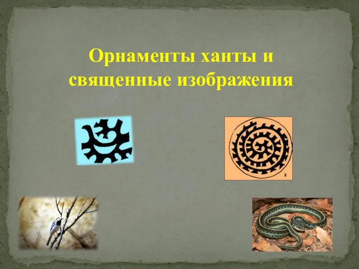 Орнаменты ханты и священные изображения
 Урок развития речи. Описание животного