- Cirras & Drawing conversion project

Содержание
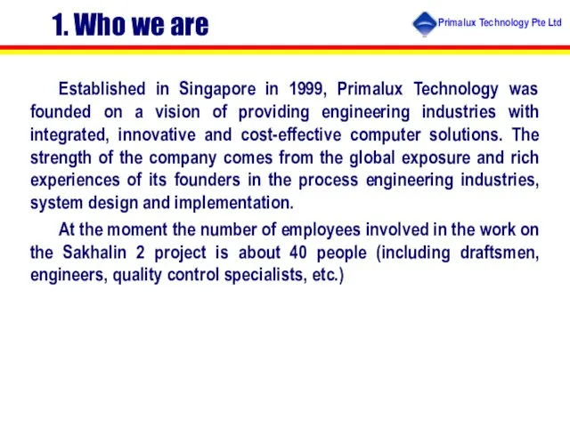
- 2. Established in Singapore in 1999, Primalux Technology was founded on a vision of providing engineering industries
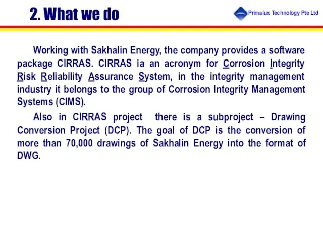
- 3. 2. What we do Working with Sakhalin Energy, the company provides a software package CIRRAS. CIRRAS
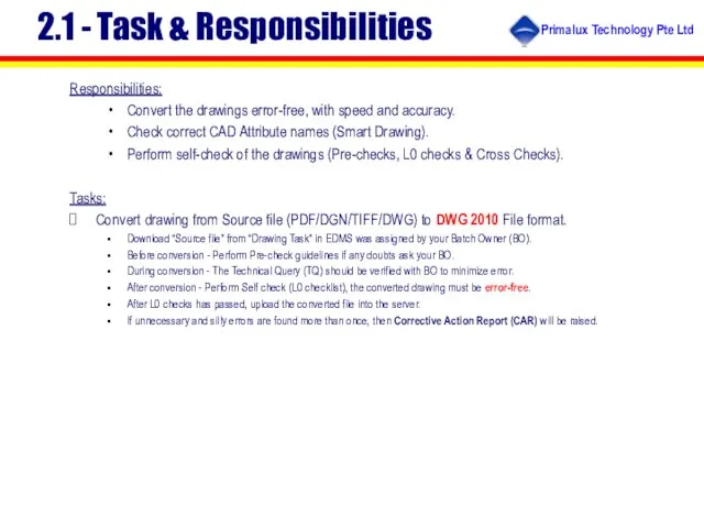
- 4. 2.1 - Task & Responsibilities Responsibilities: Convert the drawings error-free, with speed and accuracy. Check correct
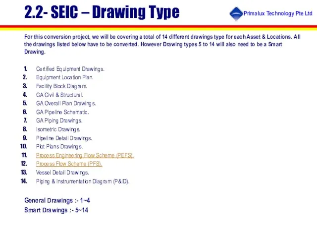
- 5. 2.2- SEIC – Drawing Type For this conversion project, we will be covering a total of
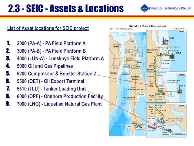
- 6. 2.3 - SEIC - Assets & Locations List of Asset locations for SEIC project 2000 (PA-A)
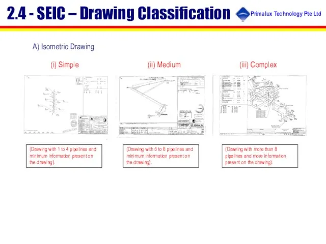
- 7. A) Isometric Drawing (i) Simple (iii) Complex (ii) Medium (Drawing with 1 to 4 pipelines and
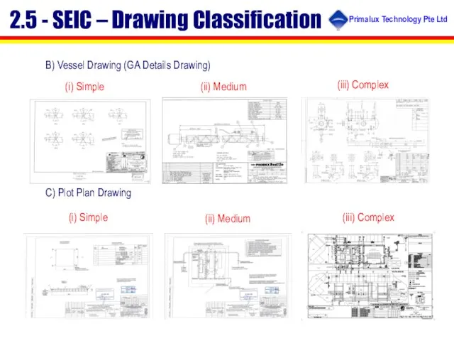
- 8. B) Vessel Drawing (GA Details Drawing) C) Plot Plan Drawing (i) Simple (iii) Complex (ii) Medium
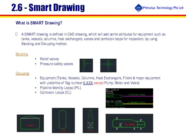
- 9. 2.6 - Smart Drawing What is SMART Drawing? A SMART drawing is defined in CAD drawing,
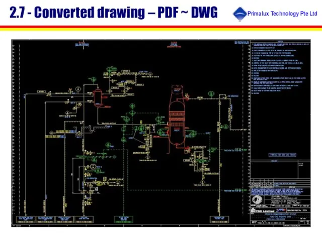
- 10. 2.7 - Converted drawing – PDF ~ DWG
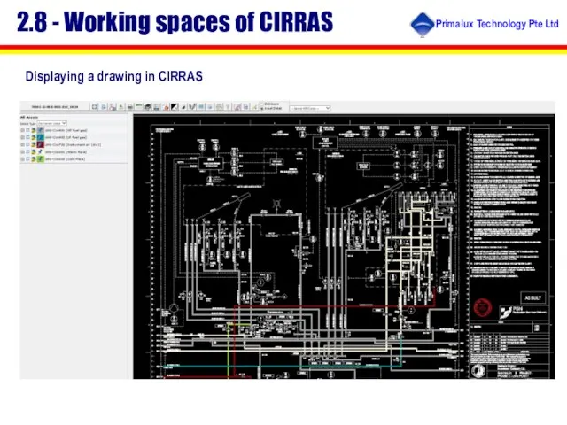
- 11. 2.8 - Working spaces of CIRRAS Displaying a drawing in CIRRAS
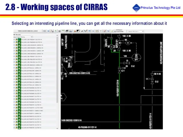
- 12. 2.8 - Working spaces of CIRRAS Selecting an interesting pipeline line, you can get all the
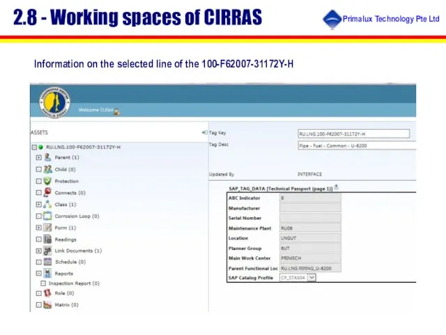
- 13. 2.8 - Working spaces of CIRRAS Information on the selected line of the 100-F62007-31172Y-H
- 14. 2.7 – Quality control All produced drawings undergo a multistage quality control system. Precheck L0 check
- 15. 3. What we can do Six specialists work in the office of the company in Yuzhno-Sakhalinsk.
- 17. Скачать презентацию
Слайд 32. What we do
Working with Sakhalin Energy, the company provides a software
2. What we do
Working with Sakhalin Energy, the company provides a software
Слайд 42.1 - Task & Responsibilities
Responsibilities:
Convert the drawings error-free, with speed and accuracy.
Check
2.1 - Task & Responsibilities
Responsibilities:
Convert the drawings error-free, with speed and accuracy.
Check
Слайд 52.2- SEIC – Drawing Type
For this conversion project, we will be covering
2.2- SEIC – Drawing Type
For this conversion project, we will be covering
Слайд 62.3 - SEIC - Assets & Locations
List of Asset locations for SEIC
2.3 - SEIC - Assets & Locations
List of Asset locations for SEIC
Слайд 7A) Isometric Drawing
(i) Simple
(iii) Complex
(ii) Medium
(Drawing with 1 to 4 pipelines and
A) Isometric Drawing
(i) Simple
(iii) Complex
(ii) Medium
(Drawing with 1 to 4 pipelines and
Слайд 8B) Vessel Drawing (GA Details Drawing)
C) Plot Plan Drawing
(i) Simple
(iii) Complex
(ii) Medium
2.5
B) Vessel Drawing (GA Details Drawing)
C) Plot Plan Drawing
(i) Simple
(iii) Complex
(ii) Medium
2.5
Слайд 92.6 - Smart Drawing
What is SMART Drawing?
A SMART drawing is defined in
2.6 - Smart Drawing
What is SMART Drawing?
A SMART drawing is defined in
Слайд 102.7 - Converted drawing – PDF ~ DWG
2.7 - Converted drawing – PDF ~ DWG
Слайд 112.8 - Working spaces of CIRRAS
Displaying a drawing in CIRRAS
2.8 - Working spaces of CIRRAS
Displaying a drawing in CIRRAS
Слайд 122.8 - Working spaces of CIRRAS
Selecting an interesting pipeline line, you can
2.8 - Working spaces of CIRRAS
Selecting an interesting pipeline line, you can
Слайд 132.8 - Working spaces of CIRRAS
Information on the selected line of the
2.8 - Working spaces of CIRRAS
Information on the selected line of the
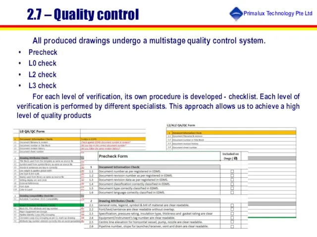
Слайд 142.7 – Quality control
All produced drawings undergo a multistage quality control system.
Precheck
L0
2.7 – Quality control
All produced drawings undergo a multistage quality control system.
Precheck
L0
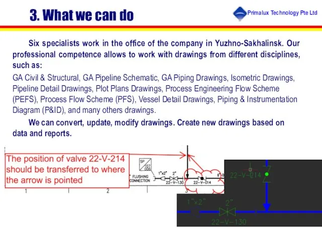
Слайд 153. What we can do
Six specialists work in the office of the
3. What we can do
Six specialists work in the office of the
 Робота з випадком. Складання картки облiку роботи
 Работа с формами. Работа с текстовыми полями и проверка их содержимого
 Операции сравнения. Программирование на языке Python
 Топ оскорблений в роблоксе
 Программирование задач с разветвленной структурой управления
 Теоретические основы информатики
 Алгоритмизация и программирование, язык Python
 Этапы создания программного обеспечения
 Интернет. Информация
 Организация вычислений в электронных таблицах. Обработка числовой информации в электронных таблицах
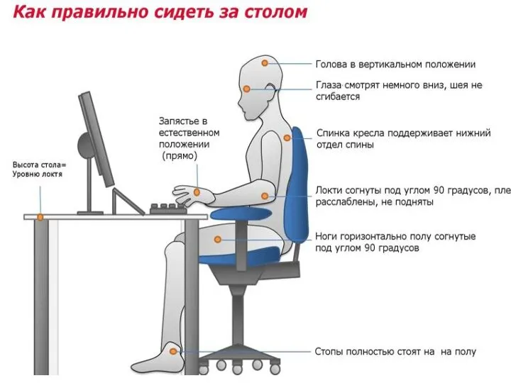 Как правильно сидеть за компьютером
 Комментарии сайт RCR
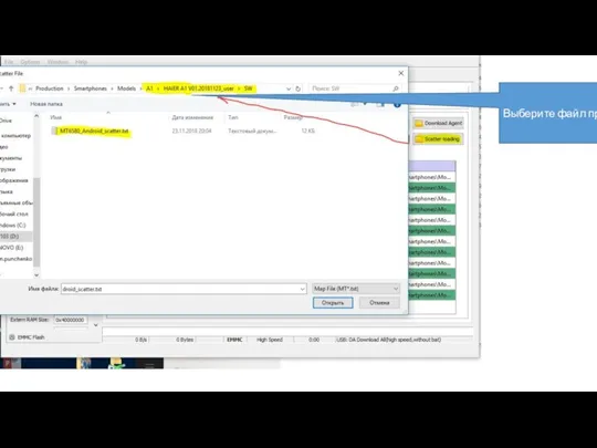 Выберите файл
 Основные этапы развития информационного общества. Этапы развития технических средств и информационных ресурсов
 Получение разрешения на добычу птицы в весенний сезон охоты
 Подготовка гиперссылки (на примере облака Мail.ru), аналогично и в других ресурсах
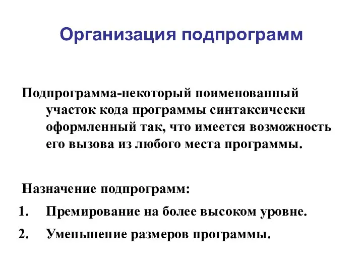 Организация подпрограмм. Программирование на яву. Лекция 5
 IT сообщество АВТФ (новичкам)
 Формирование в случае отсутствия информации
 Паттерны и фреймворки в архитектуре ИС
 Восьмеричная система счисления
 Паскаль. Теория
 Установка Aris Express
 Электронная почта
 Организация данных в ГИС. Источники данных для ГИС. Растровая модель данных. Векторная модель данных
 Телеканал ТНТ
 Методы неразрушающего контроля
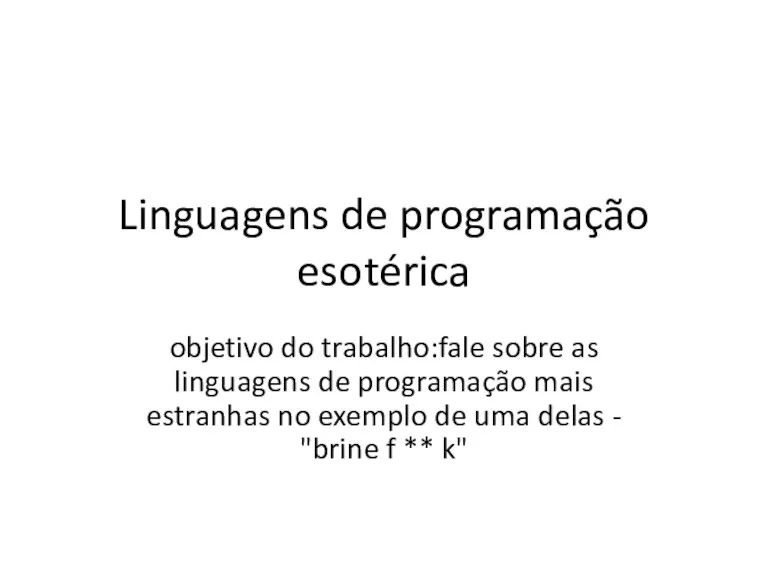 Linguagens de programação esotérica