- (009)Pulse Gen Assy Intro rev C SSlimk

Содержание
- 2. © 2001, Halliburton Energy Services, Inc. January 12, 2001 Pulse Generator Assembly Objectives At the completion
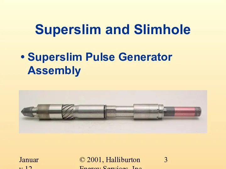
- 3. © 2001, Halliburton Energy Services, Inc. January 12, 2001 Superslim and Slimhole Superslim Pulse Generator Assembly
- 4. © 2001, Halliburton Energy Services, Inc. January 12, 2001 What does a Pulse Generator Assembly do?
- 5. © 2001, Halliburton Energy Services, Inc. January 12, 2001 What makes a Pulse Generator Assembly The
- 6. © 2001, Halliburton Energy Services, Inc. January 12, 2001 What makes a Pulse Generator Assembly The
- 7. © 2001, Halliburton Energy Services, Inc. January 12, 2001 The Pulser
- 8. © 2001, Halliburton Energy Services, Inc. January 12, 2001 The Pulser Generates electrical and hydraulic power
- 9. © 2001, Halliburton Energy Services, Inc. January 12, 2001 The Flowgear Most of the flowgear comes
- 10. © 2001, Halliburton Energy Services, Inc. January 12, 2001 Pulse Generator Assembly The four systems can
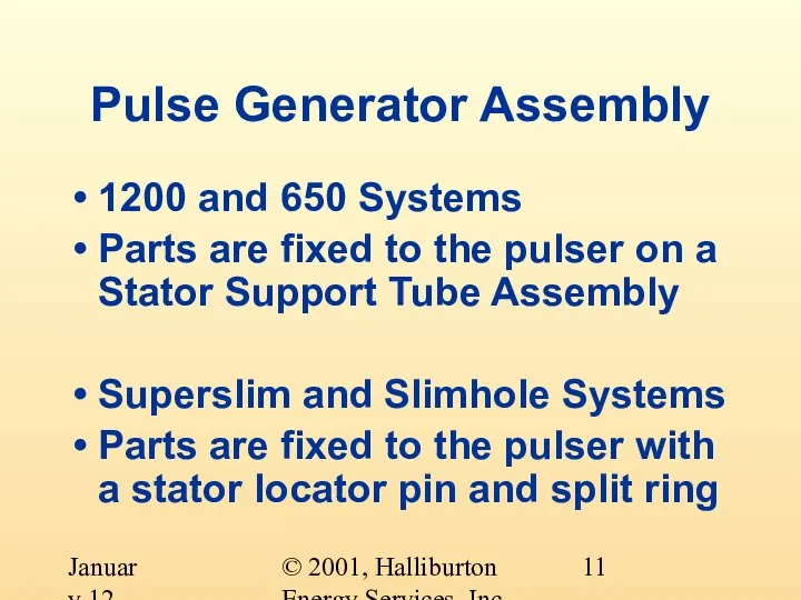
- 11. © 2001, Halliburton Energy Services, Inc. January 12, 2001 Pulse Generator Assembly 1200 and 650 Systems
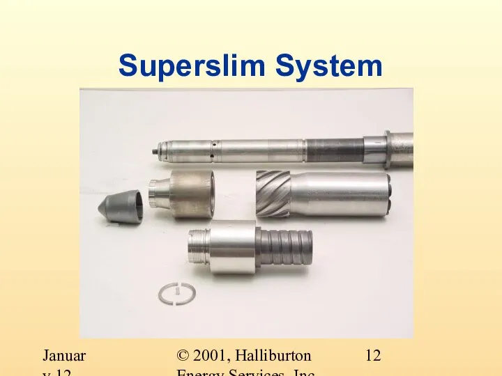
- 12. © 2001, Halliburton Energy Services, Inc. January 12, 2001 Superslim System
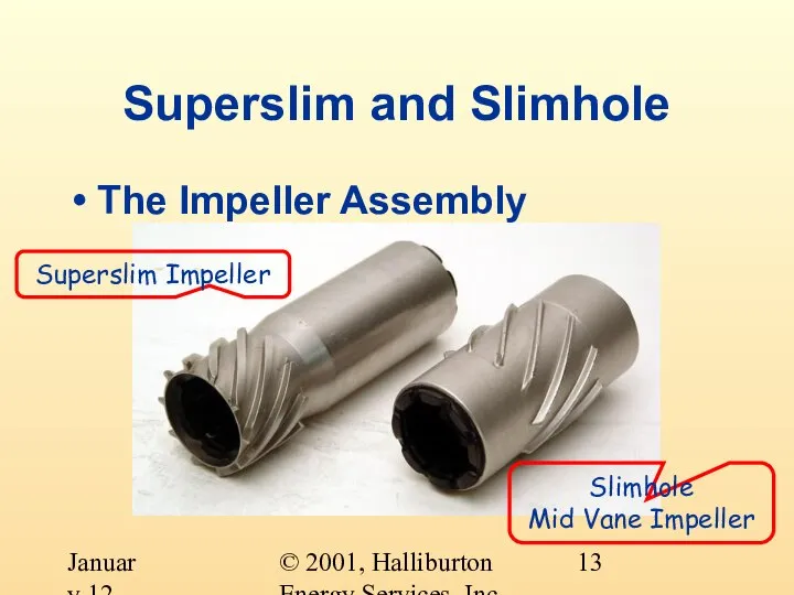
- 13. © 2001, Halliburton Energy Services, Inc. January 12, 2001 Superslim and Slimhole The Impeller Assembly Slimhole
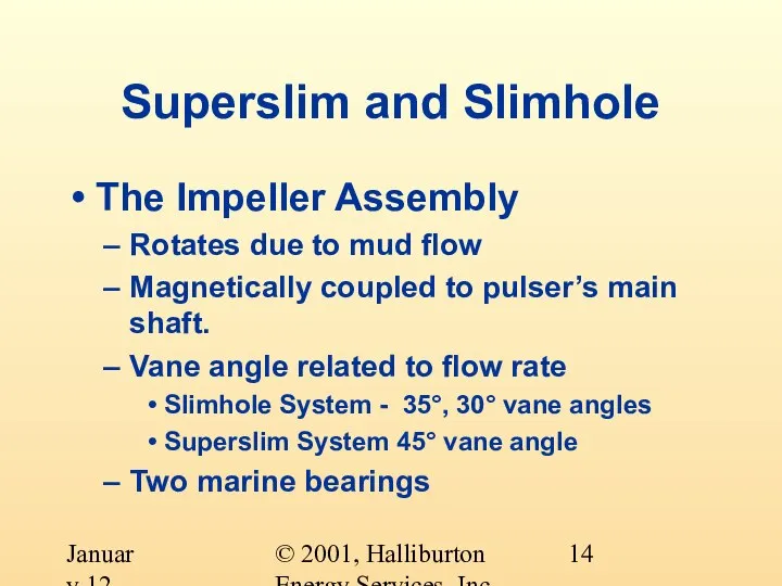
- 14. © 2001, Halliburton Energy Services, Inc. January 12, 2001 Superslim and Slimhole The Impeller Assembly Rotates
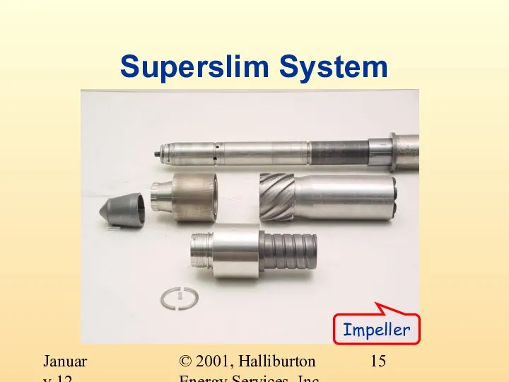
- 15. © 2001, Halliburton Energy Services, Inc. January 12, 2001 Superslim System Impeller
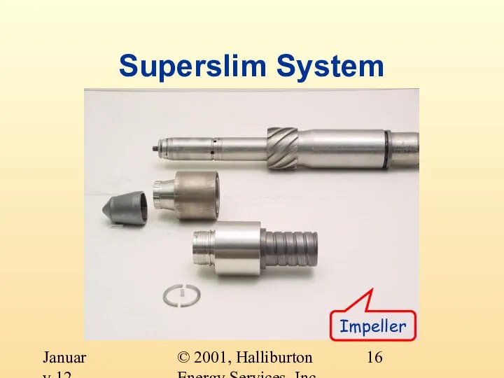
- 16. © 2001, Halliburton Energy Services, Inc. January 12, 2001 Superslim System Impeller
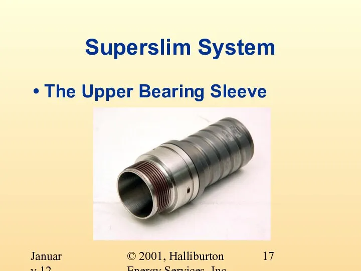
- 17. © 2001, Halliburton Energy Services, Inc. January 12, 2001 Superslim System The Upper Bearing Sleeve
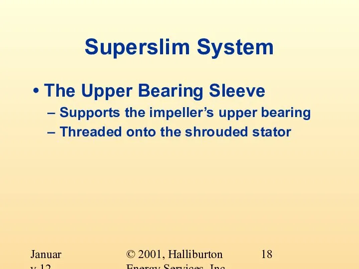
- 18. © 2001, Halliburton Energy Services, Inc. January 12, 2001 Superslim System The Upper Bearing Sleeve Supports
- 19. © 2001, Halliburton Energy Services, Inc. January 12, 2001 Superslim and Slimhole The Shrouded Stator
- 20. © 2001, Halliburton Energy Services, Inc. January 12, 2001 Superslim and Slimhole The Shrouded Stator Pinned
- 21. © 2001, Halliburton Energy Services, Inc. January 12, 2001 Superslim and Slimhole The Shrouded Stator Assembly
- 22. © 2001, Halliburton Energy Services, Inc. January 12, 2001 Superslim and Slimhole The Shrouded Stator Assembly
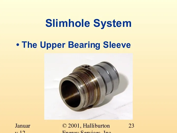
- 23. © 2001, Halliburton Energy Services, Inc. January 12, 2001 Slimhole System The Upper Bearing Sleeve
- 24. © 2001, Halliburton Energy Services, Inc. January 12, 2001 Slimhole System The Upper Bearing Sleeve Supports
- 25. © 2001, Halliburton Energy Services, Inc. January 12, 2001 Slimhole System The Flow Diverter
- 26. © 2001, Halliburton Energy Services, Inc. January 12, 2001 Slimhole System The Flow Diverter Directs flow
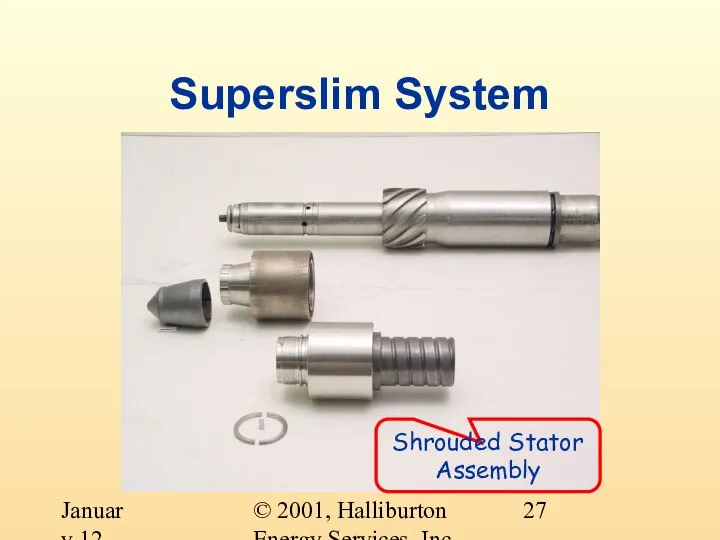
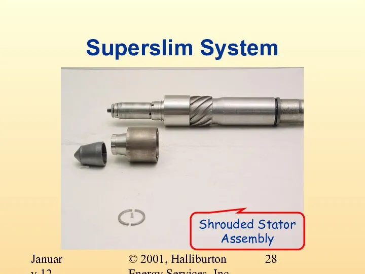
- 27. © 2001, Halliburton Energy Services, Inc. January 12, 2001 Superslim System Shrouded Stator Assembly
- 28. © 2001, Halliburton Energy Services, Inc. January 12, 2001 Superslim System Shrouded Stator Assembly
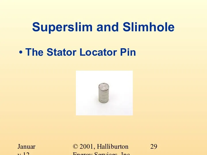
- 29. © 2001, Halliburton Energy Services, Inc. January 12, 2001 Superslim and Slimhole The Stator Locator Pin
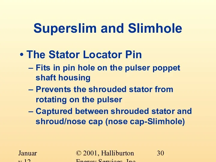
- 30. © 2001, Halliburton Energy Services, Inc. January 12, 2001 Superslim and Slimhole The Stator Locator Pin
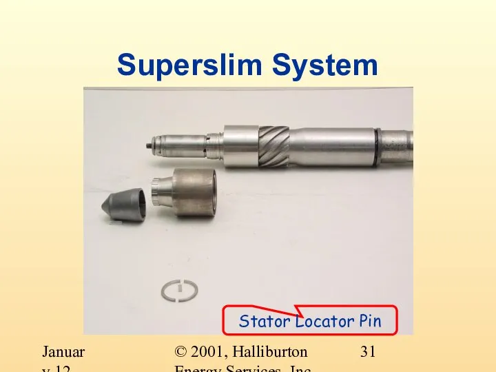
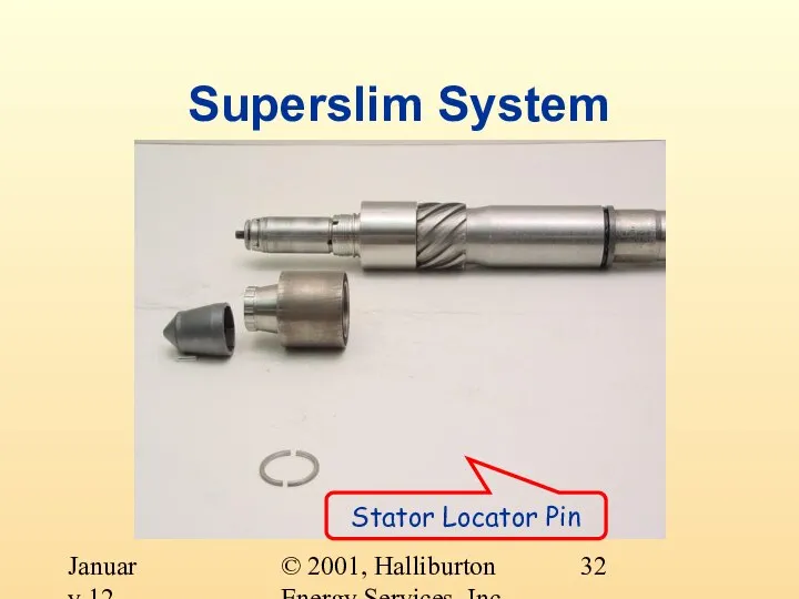
- 31. © 2001, Halliburton Energy Services, Inc. January 12, 2001 Superslim System Stator Locator Pin
- 32. © 2001, Halliburton Energy Services, Inc. January 12, 2001 Superslim System Stator Locator Pin
- 33. © 2001, Halliburton Energy Services, Inc. January 12, 2001 Superslim and Slimhole
- 34. © 2001, Halliburton Energy Services, Inc. January 12, 2001 Superslim and Slimhole
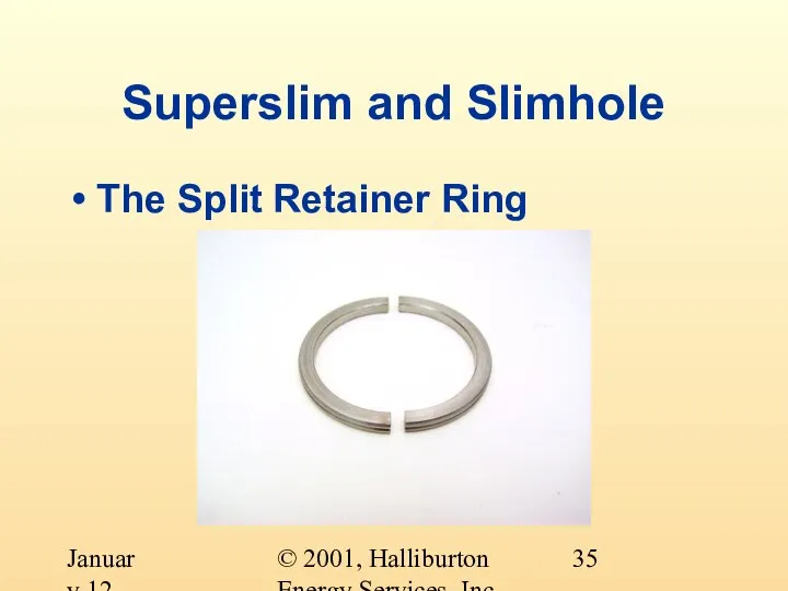
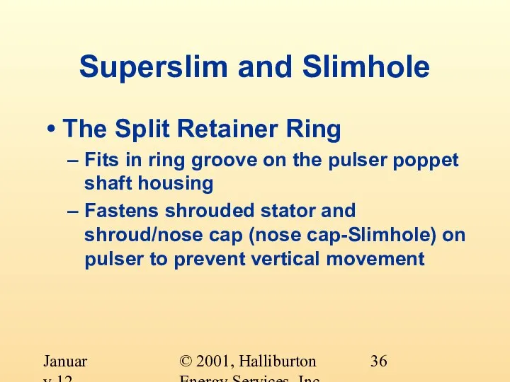
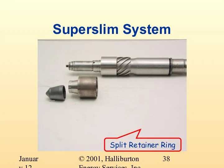
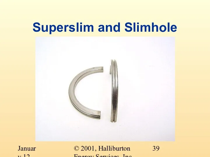
- 35. © 2001, Halliburton Energy Services, Inc. January 12, 2001 Superslim and Slimhole The Split Retainer Ring
- 36. © 2001, Halliburton Energy Services, Inc. January 12, 2001 Superslim and Slimhole The Split Retainer Ring
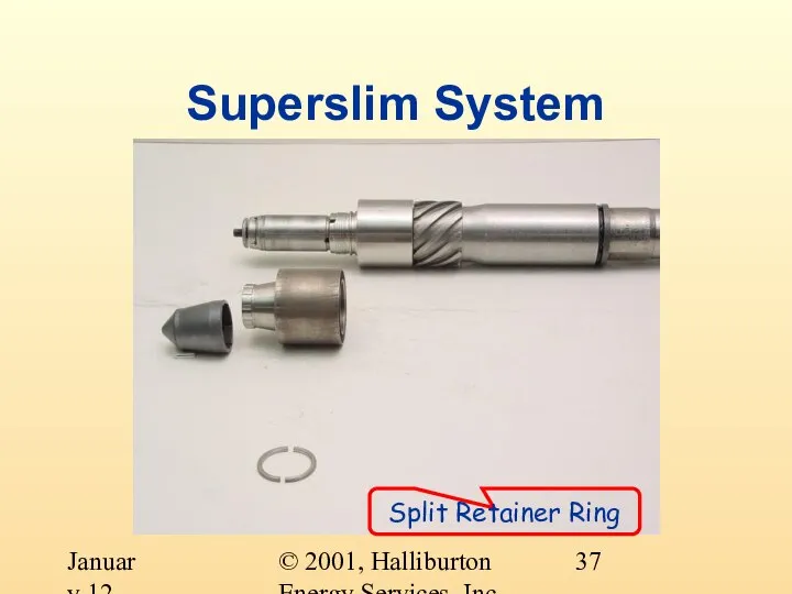
- 37. © 2001, Halliburton Energy Services, Inc. January 12, 2001 Superslim System Split Retainer Ring
- 38. © 2001, Halliburton Energy Services, Inc. January 12, 2001 Superslim System Split Retainer Ring
- 39. © 2001, Halliburton Energy Services, Inc. January 12, 2001 Superslim and Slimhole
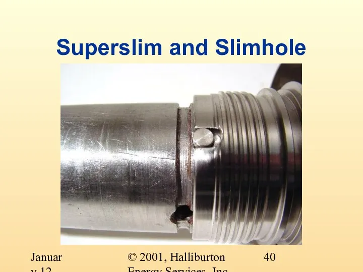
- 40. © 2001, Halliburton Energy Services, Inc. January 12, 2001 Superslim and Slimhole
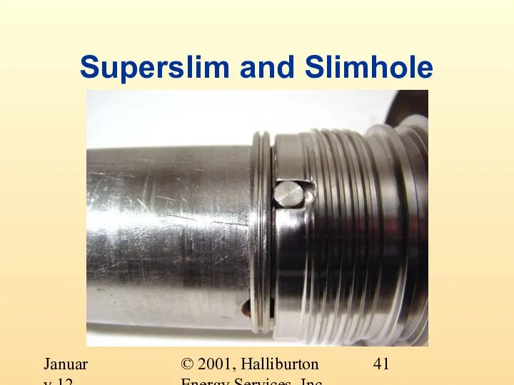
- 41. © 2001, Halliburton Energy Services, Inc. January 12, 2001 Superslim and Slimhole
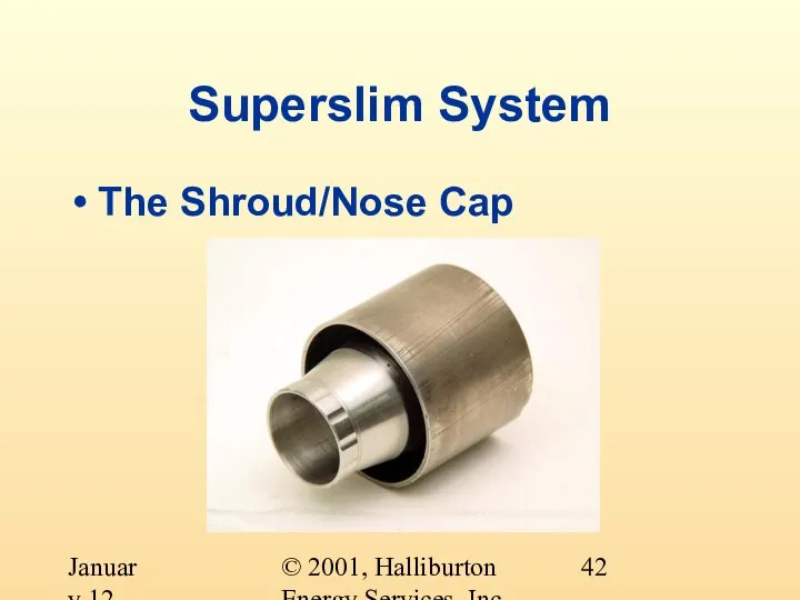
- 42. © 2001, Halliburton Energy Services, Inc. January 12, 2001 Superslim System The Shroud/Nose Cap
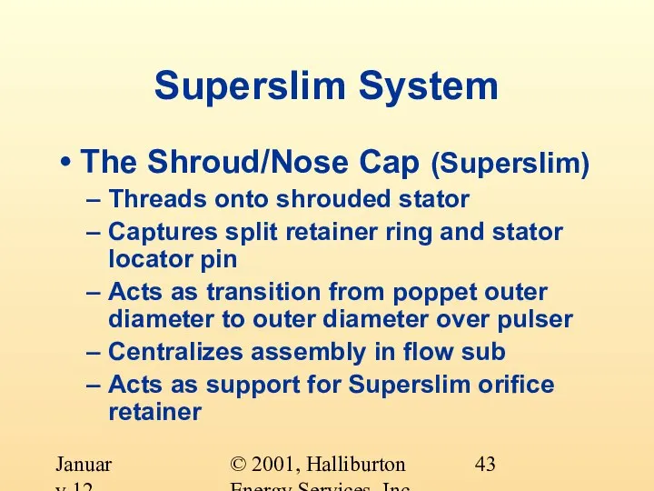
- 43. © 2001, Halliburton Energy Services, Inc. January 12, 2001 Superslim System The Shroud/Nose Cap (Superslim) Threads
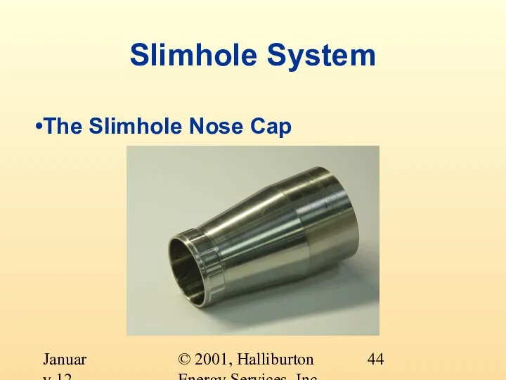
- 44. © 2001, Halliburton Energy Services, Inc. January 12, 2001 Slimhole System The Slimhole Nose Cap
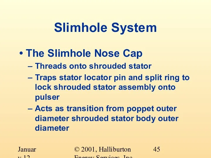
- 45. © 2001, Halliburton Energy Services, Inc. January 12, 2001 Slimhole System The Slimhole Nose Cap Threads
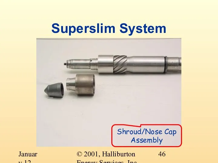
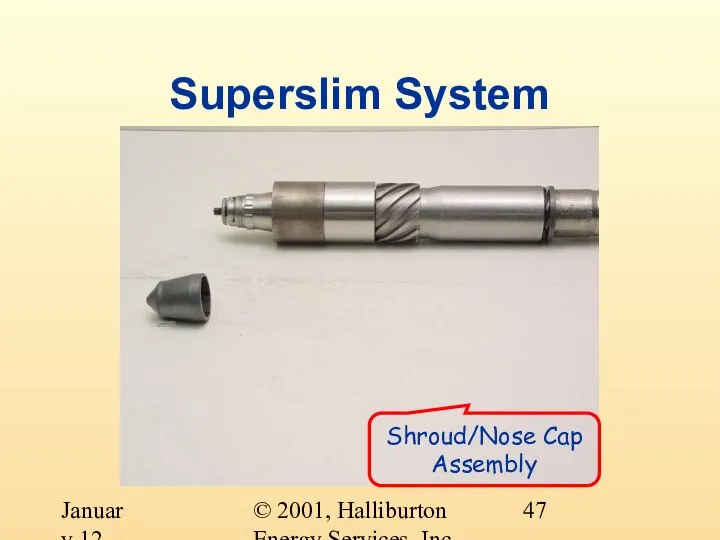
- 46. © 2001, Halliburton Energy Services, Inc. January 12, 2001 Superslim System Shroud/Nose Cap Assembly
- 47. © 2001, Halliburton Energy Services, Inc. January 12, 2001 Superslim System Shroud/Nose Cap Assembly
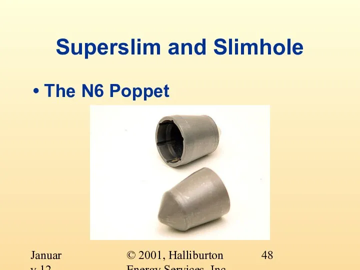
- 48. © 2001, Halliburton Energy Services, Inc. January 12, 2001 Superslim and Slimhole The N6 Poppet
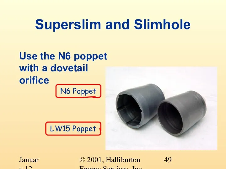
- 49. © 2001, Halliburton Energy Services, Inc. January 12, 2001 Superslim and Slimhole Use the N6 poppet
- 50. © 2001, Halliburton Energy Services, Inc. January 12, 2001 Superslim and Slimhole The Poppet Threads onto
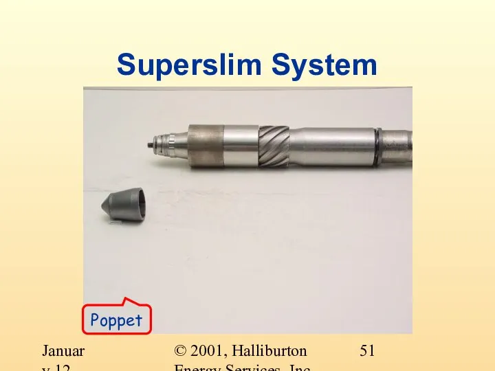
- 51. © 2001, Halliburton Energy Services, Inc. January 12, 2001 Superslim System Poppet
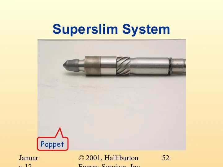
- 52. © 2001, Halliburton Energy Services, Inc. January 12, 2001 Superslim System Poppet
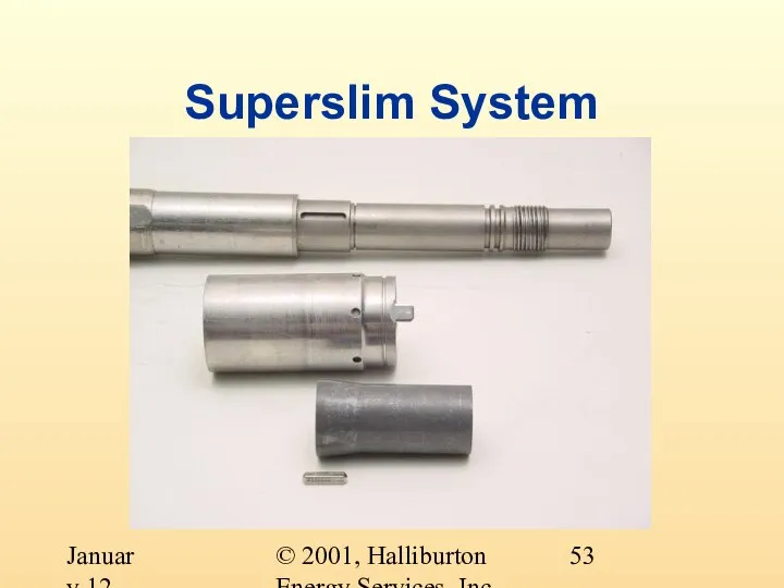
- 53. © 2001, Halliburton Energy Services, Inc. January 12, 2001 Superslim System
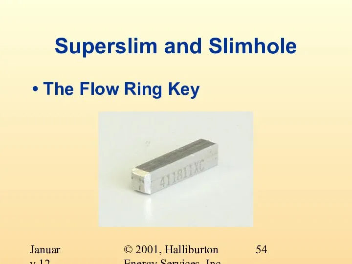
- 54. © 2001, Halliburton Energy Services, Inc. January 12, 2001 Superslim and Slimhole The Flow Ring Key
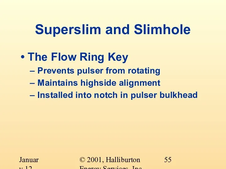
- 55. © 2001, Halliburton Energy Services, Inc. January 12, 2001 Superslim and Slimhole The Flow Ring Key
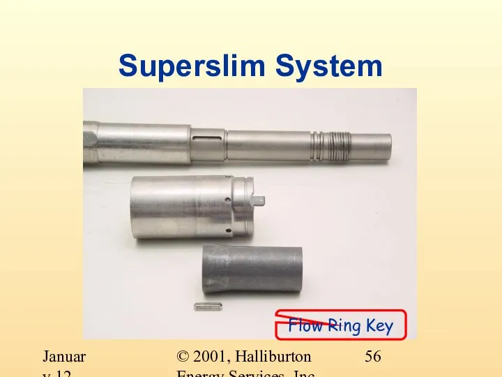
- 56. © 2001, Halliburton Energy Services, Inc. January 12, 2001 Superslim System Flow Ring Key
- 57. © 2001, Halliburton Energy Services, Inc. January 12, 2001 Superslim System Flow Ring Key
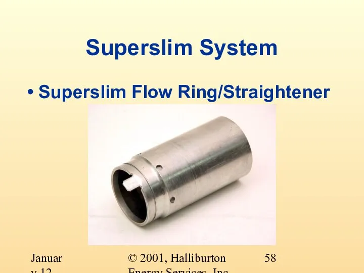
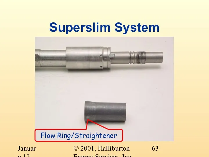
- 58. © 2001, Halliburton Energy Services, Inc. January 12, 2001 Superslim System Superslim Flow Ring/Straightener
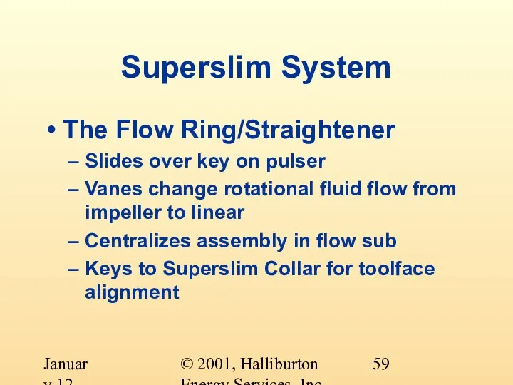
- 59. © 2001, Halliburton Energy Services, Inc. January 12, 2001 Superslim System The Flow Ring/Straightener Slides over
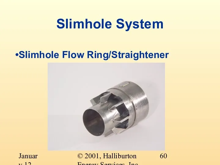
- 60. © 2001, Halliburton Energy Services, Inc. January 12, 2001 Slimhole System Slimhole Flow Ring/Straightener
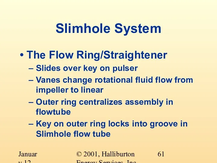
- 61. © 2001, Halliburton Energy Services, Inc. January 12, 2001 Slimhole System The Flow Ring/Straightener Slides over
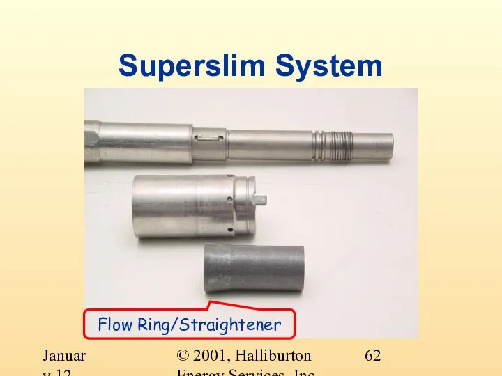
- 62. © 2001, Halliburton Energy Services, Inc. January 12, 2001 Superslim System Flow Ring/Straightener
- 63. © 2001, Halliburton Energy Services, Inc. January 12, 2001 Superslim System Flow Ring/Straightener
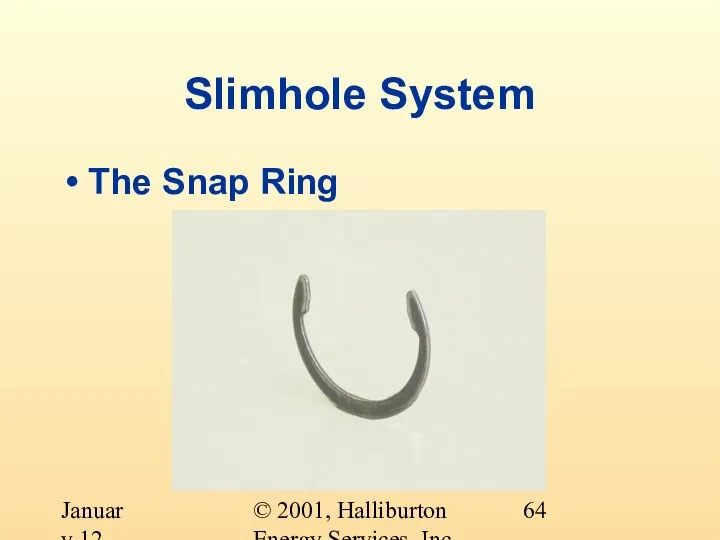
- 64. © 2001, Halliburton Energy Services, Inc. January 12, 2001 Slimhole System The Snap Ring
- 65. © 2001, Halliburton Energy Services, Inc. January 12, 2001 Slimhole System The Snap Ring Holds flow
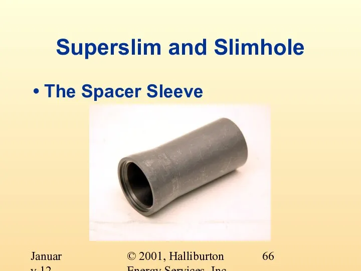
- 66. © 2001, Halliburton Energy Services, Inc. January 12, 2001 Superslim and Slimhole The Spacer Sleeve
- 67. © 2001, Halliburton Energy Services, Inc. January 12, 2001 Superslim and Slimhole The Spacer Sleeve Provides
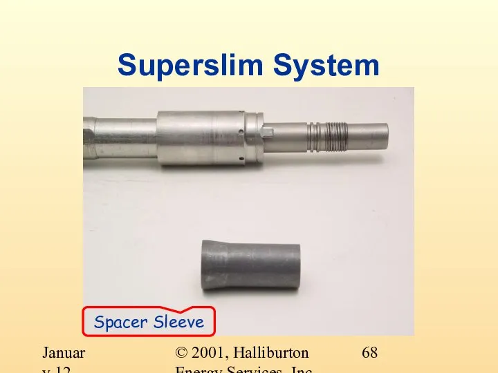
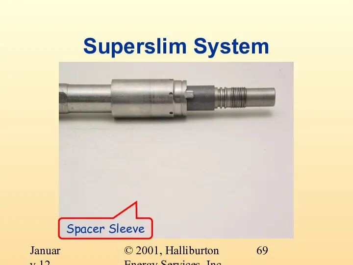
- 68. © 2001, Halliburton Energy Services, Inc. January 12, 2001 Superslim System Spacer Sleeve
- 69. © 2001, Halliburton Energy Services, Inc. January 12, 2001 Superslim System Spacer Sleeve
- 71. Скачать презентацию
Слайд 2© 2001, Halliburton Energy Services, Inc.
January 12, 2001
Pulse Generator Assembly Objectives
At the
© 2001, Halliburton Energy Services, Inc.
January 12, 2001
Pulse Generator Assembly Objectives
At the

Слайд 3© 2001, Halliburton Energy Services, Inc.
January 12, 2001
Superslim and Slimhole
Superslim Pulse Generator
© 2001, Halliburton Energy Services, Inc.
January 12, 2001
Superslim and Slimhole
Superslim Pulse Generator
Слайд 4© 2001, Halliburton Energy Services, Inc.
January 12, 2001
What does a Pulse Generator
© 2001, Halliburton Energy Services, Inc.
January 12, 2001
What does a Pulse Generator

Слайд 5© 2001, Halliburton Energy Services, Inc.
January 12, 2001
What makes a Pulse Generator
© 2001, Halliburton Energy Services, Inc.
January 12, 2001
What makes a Pulse Generator

Слайд 6© 2001, Halliburton Energy Services, Inc.
January 12, 2001
What makes a Pulse Generator
© 2001, Halliburton Energy Services, Inc.
January 12, 2001
What makes a Pulse Generator

Слайд 7© 2001, Halliburton Energy Services, Inc.
January 12, 2001
The Pulser
© 2001, Halliburton Energy Services, Inc.
January 12, 2001
The Pulser

Слайд 8© 2001, Halliburton Energy Services, Inc.
January 12, 2001
The Pulser
Generates electrical and hydraulic
© 2001, Halliburton Energy Services, Inc.
January 12, 2001
The Pulser
Generates electrical and hydraulic
Слайд 9© 2001, Halliburton Energy Services, Inc.
January 12, 2001
The Flowgear
Most of the flowgear
© 2001, Halliburton Energy Services, Inc.
January 12, 2001
The Flowgear
Most of the flowgear
Слайд 10© 2001, Halliburton Energy Services, Inc.
January 12, 2001
Pulse Generator Assembly
The four systems
© 2001, Halliburton Energy Services, Inc.
January 12, 2001
Pulse Generator Assembly
The four systems
Слайд 11© 2001, Halliburton Energy Services, Inc.
January 12, 2001
Pulse Generator Assembly
1200 and 650
© 2001, Halliburton Energy Services, Inc.
January 12, 2001
Pulse Generator Assembly
1200 and 650
Слайд 12© 2001, Halliburton Energy Services, Inc.
January 12, 2001
Superslim System
© 2001, Halliburton Energy Services, Inc.
January 12, 2001
Superslim System
Слайд 13© 2001, Halliburton Energy Services, Inc.
January 12, 2001
Superslim and Slimhole
The Impeller Assembly
Slimhole
Mid
© 2001, Halliburton Energy Services, Inc.
January 12, 2001
Superslim and Slimhole
The Impeller Assembly
Slimhole
Mid
Слайд 14© 2001, Halliburton Energy Services, Inc.
January 12, 2001
Superslim and Slimhole
The Impeller Assembly
Rotates
© 2001, Halliburton Energy Services, Inc.
January 12, 2001
Superslim and Slimhole
The Impeller Assembly
Rotates
Слайд 15© 2001, Halliburton Energy Services, Inc.
January 12, 2001
Superslim System
Impeller
© 2001, Halliburton Energy Services, Inc.
January 12, 2001
Superslim System
Impeller
Слайд 16© 2001, Halliburton Energy Services, Inc.
January 12, 2001
Superslim System
Impeller
© 2001, Halliburton Energy Services, Inc.
January 12, 2001
Superslim System
Impeller
Слайд 17© 2001, Halliburton Energy Services, Inc.
January 12, 2001
Superslim System
The Upper Bearing Sleeve
© 2001, Halliburton Energy Services, Inc.
January 12, 2001
Superslim System
The Upper Bearing Sleeve
Слайд 18© 2001, Halliburton Energy Services, Inc.
January 12, 2001
Superslim System
The Upper Bearing Sleeve
Supports
© 2001, Halliburton Energy Services, Inc.
January 12, 2001
Superslim System
The Upper Bearing Sleeve
Supports
Слайд 19© 2001, Halliburton Energy Services, Inc.
January 12, 2001
Superslim and Slimhole
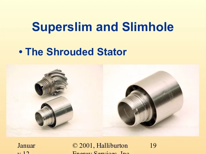
The Shrouded Stator
© 2001, Halliburton Energy Services, Inc.
January 12, 2001
Superslim and Slimhole
The Shrouded Stator
Слайд 20© 2001, Halliburton Energy Services, Inc.
January 12, 2001
Superslim and Slimhole
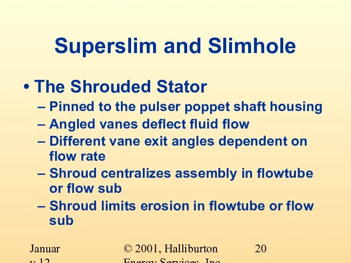
The Shrouded Stator
Pinned
© 2001, Halliburton Energy Services, Inc.
January 12, 2001
Superslim and Slimhole
The Shrouded Stator
Pinned
Слайд 21© 2001, Halliburton Energy Services, Inc.
January 12, 2001
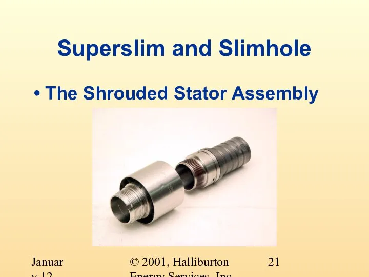
Superslim and Slimhole
The Shrouded Stator
© 2001, Halliburton Energy Services, Inc.
January 12, 2001
Superslim and Slimhole
The Shrouded Stator
Слайд 22© 2001, Halliburton Energy Services, Inc.
January 12, 2001
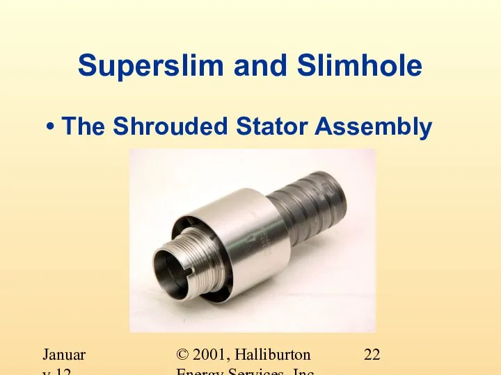
Superslim and Slimhole
The Shrouded Stator
© 2001, Halliburton Energy Services, Inc.
January 12, 2001
Superslim and Slimhole
The Shrouded Stator
Слайд 23© 2001, Halliburton Energy Services, Inc.
January 12, 2001
Slimhole System
The Upper Bearing Sleeve
© 2001, Halliburton Energy Services, Inc.
January 12, 2001
Slimhole System
The Upper Bearing Sleeve
Слайд 24© 2001, Halliburton Energy Services, Inc.
January 12, 2001
Slimhole System
The Upper Bearing Sleeve
Supports
© 2001, Halliburton Energy Services, Inc.
January 12, 2001
Slimhole System
The Upper Bearing Sleeve
Supports
Слайд 25© 2001, Halliburton Energy Services, Inc.
January 12, 2001
Slimhole System
The Flow Diverter
© 2001, Halliburton Energy Services, Inc.
January 12, 2001
Slimhole System
The Flow Diverter

Слайд 26© 2001, Halliburton Energy Services, Inc.
January 12, 2001
Slimhole System
The Flow Diverter
Directs flow
© 2001, Halliburton Energy Services, Inc.
January 12, 2001
Slimhole System
The Flow Diverter
Directs flow
Слайд 27© 2001, Halliburton Energy Services, Inc.
January 12, 2001
Superslim System
Shrouded Stator
Assembly
© 2001, Halliburton Energy Services, Inc.
January 12, 2001
Superslim System
Shrouded Stator
Assembly
Слайд 28© 2001, Halliburton Energy Services, Inc.
January 12, 2001
Superslim System
Shrouded Stator
Assembly
© 2001, Halliburton Energy Services, Inc.
January 12, 2001
Superslim System
Shrouded Stator
Assembly
Слайд 29© 2001, Halliburton Energy Services, Inc.
January 12, 2001
Superslim and Slimhole
The Stator Locator
© 2001, Halliburton Energy Services, Inc.
January 12, 2001
Superslim and Slimhole
The Stator Locator
Слайд 30© 2001, Halliburton Energy Services, Inc.
January 12, 2001
Superslim and Slimhole
The Stator Locator
© 2001, Halliburton Energy Services, Inc.
January 12, 2001
Superslim and Slimhole
The Stator Locator
Слайд 31© 2001, Halliburton Energy Services, Inc.
January 12, 2001
Superslim System
Stator Locator Pin
© 2001, Halliburton Energy Services, Inc.
January 12, 2001
Superslim System
Stator Locator Pin
Слайд 32© 2001, Halliburton Energy Services, Inc.
January 12, 2001
Superslim System
Stator Locator Pin
© 2001, Halliburton Energy Services, Inc.
January 12, 2001
Superslim System
Stator Locator Pin
Слайд 33© 2001, Halliburton Energy Services, Inc.
January 12, 2001
Superslim and Slimhole
© 2001, Halliburton Energy Services, Inc.
January 12, 2001
Superslim and Slimhole

Слайд 34© 2001, Halliburton Energy Services, Inc.
January 12, 2001
Superslim and Slimhole
© 2001, Halliburton Energy Services, Inc.
January 12, 2001
Superslim and Slimhole

Слайд 35© 2001, Halliburton Energy Services, Inc.
January 12, 2001
Superslim and Slimhole
The Split Retainer
© 2001, Halliburton Energy Services, Inc.
January 12, 2001
Superslim and Slimhole
The Split Retainer
Слайд 36© 2001, Halliburton Energy Services, Inc.
January 12, 2001
Superslim and Slimhole
The Split Retainer
© 2001, Halliburton Energy Services, Inc.
January 12, 2001
Superslim and Slimhole
The Split Retainer
Слайд 37© 2001, Halliburton Energy Services, Inc.
January 12, 2001
Superslim System
Split Retainer Ring
© 2001, Halliburton Energy Services, Inc.
January 12, 2001
Superslim System
Split Retainer Ring
Слайд 38© 2001, Halliburton Energy Services, Inc.
January 12, 2001
Superslim System
Split Retainer Ring
© 2001, Halliburton Energy Services, Inc.
January 12, 2001
Superslim System
Split Retainer Ring
Слайд 39© 2001, Halliburton Energy Services, Inc.
January 12, 2001
Superslim and Slimhole
© 2001, Halliburton Energy Services, Inc.
January 12, 2001
Superslim and Slimhole
Слайд 40© 2001, Halliburton Energy Services, Inc.
January 12, 2001
Superslim and Slimhole
© 2001, Halliburton Energy Services, Inc.
January 12, 2001
Superslim and Slimhole
Слайд 41© 2001, Halliburton Energy Services, Inc.
January 12, 2001
Superslim and Slimhole
© 2001, Halliburton Energy Services, Inc.
January 12, 2001
Superslim and Slimhole
Слайд 42© 2001, Halliburton Energy Services, Inc.
January 12, 2001
Superslim System
The Shroud/Nose Cap
© 2001, Halliburton Energy Services, Inc.
January 12, 2001
Superslim System
The Shroud/Nose Cap
Слайд 43© 2001, Halliburton Energy Services, Inc.
January 12, 2001
Superslim System
The Shroud/Nose Cap (Superslim)
Threads
© 2001, Halliburton Energy Services, Inc.
January 12, 2001
Superslim System
The Shroud/Nose Cap (Superslim)
Threads
Слайд 44© 2001, Halliburton Energy Services, Inc.
January 12, 2001
Slimhole System
The Slimhole Nose Cap
© 2001, Halliburton Energy Services, Inc.
January 12, 2001
Slimhole System
The Slimhole Nose Cap
Слайд 45© 2001, Halliburton Energy Services, Inc.
January 12, 2001
Slimhole System
The Slimhole Nose Cap
Threads
© 2001, Halliburton Energy Services, Inc.
January 12, 2001
Slimhole System
The Slimhole Nose Cap
Threads
Слайд 46© 2001, Halliburton Energy Services, Inc.
January 12, 2001
Superslim System
Shroud/Nose Cap
Assembly
© 2001, Halliburton Energy Services, Inc.
January 12, 2001
Superslim System
Shroud/Nose Cap
Assembly
Слайд 47© 2001, Halliburton Energy Services, Inc.
January 12, 2001
Superslim System
Shroud/Nose Cap
Assembly
© 2001, Halliburton Energy Services, Inc.
January 12, 2001
Superslim System
Shroud/Nose Cap
Assembly
Слайд 48© 2001, Halliburton Energy Services, Inc.
January 12, 2001
Superslim and Slimhole
The N6 Poppet
© 2001, Halliburton Energy Services, Inc.
January 12, 2001
Superslim and Slimhole
The N6 Poppet
Слайд 49© 2001, Halliburton Energy Services, Inc.
January 12, 2001
Superslim and Slimhole
Use the N6
© 2001, Halliburton Energy Services, Inc.
January 12, 2001
Superslim and Slimhole
Use the N6
Слайд 50© 2001, Halliburton Energy Services, Inc.
January 12, 2001
Superslim and Slimhole
The Poppet
Threads onto
© 2001, Halliburton Energy Services, Inc.
January 12, 2001
Superslim and Slimhole
The Poppet
Threads onto
Слайд 51© 2001, Halliburton Energy Services, Inc.
January 12, 2001
Superslim System
Poppet
© 2001, Halliburton Energy Services, Inc.
January 12, 2001
Superslim System
Poppet
Слайд 52© 2001, Halliburton Energy Services, Inc.
January 12, 2001
Superslim System
Poppet
© 2001, Halliburton Energy Services, Inc.
January 12, 2001
Superslim System
Poppet
Слайд 53© 2001, Halliburton Energy Services, Inc.
January 12, 2001
Superslim System
© 2001, Halliburton Energy Services, Inc.
January 12, 2001
Superslim System
Слайд 54© 2001, Halliburton Energy Services, Inc.
January 12, 2001
Superslim and Slimhole
The Flow Ring
© 2001, Halliburton Energy Services, Inc.
January 12, 2001
Superslim and Slimhole
The Flow Ring
Слайд 55© 2001, Halliburton Energy Services, Inc.
January 12, 2001
Superslim and Slimhole
The Flow Ring
© 2001, Halliburton Energy Services, Inc.
January 12, 2001
Superslim and Slimhole
The Flow Ring
Слайд 56© 2001, Halliburton Energy Services, Inc.
January 12, 2001
Superslim System
Flow Ring Key
© 2001, Halliburton Energy Services, Inc.
January 12, 2001
Superslim System
Flow Ring Key
Слайд 57© 2001, Halliburton Energy Services, Inc.
January 12, 2001
Superslim System
Flow Ring Key
© 2001, Halliburton Energy Services, Inc.
January 12, 2001
Superslim System
Flow Ring Key

Слайд 58© 2001, Halliburton Energy Services, Inc.
January 12, 2001
Superslim System
Superslim Flow Ring/Straightener
© 2001, Halliburton Energy Services, Inc.
January 12, 2001
Superslim System
Superslim Flow Ring/Straightener
Слайд 59© 2001, Halliburton Energy Services, Inc.
January 12, 2001
Superslim System
The Flow Ring/Straightener
Slides over
© 2001, Halliburton Energy Services, Inc.
January 12, 2001
Superslim System
The Flow Ring/Straightener
Slides over
Слайд 60© 2001, Halliburton Energy Services, Inc.
January 12, 2001
Slimhole System
Slimhole Flow Ring/Straightener
© 2001, Halliburton Energy Services, Inc.
January 12, 2001
Slimhole System
Slimhole Flow Ring/Straightener
Слайд 61© 2001, Halliburton Energy Services, Inc.
January 12, 2001
Slimhole System
The Flow Ring/Straightener
Slides over
© 2001, Halliburton Energy Services, Inc.
January 12, 2001
Slimhole System
The Flow Ring/Straightener
Slides over
Слайд 62© 2001, Halliburton Energy Services, Inc.
January 12, 2001
Superslim System
Flow Ring/Straightener
© 2001, Halliburton Energy Services, Inc.
January 12, 2001
Superslim System
Flow Ring/Straightener
Слайд 63© 2001, Halliburton Energy Services, Inc.
January 12, 2001
Superslim System
Flow Ring/Straightener
© 2001, Halliburton Energy Services, Inc.
January 12, 2001
Superslim System
Flow Ring/Straightener
Слайд 64© 2001, Halliburton Energy Services, Inc.
January 12, 2001
Slimhole System
The Snap Ring
© 2001, Halliburton Energy Services, Inc.
January 12, 2001
Slimhole System
The Snap Ring
Слайд 65© 2001, Halliburton Energy Services, Inc.
January 12, 2001
Slimhole System
The Snap Ring
Holds flow
© 2001, Halliburton Energy Services, Inc.
January 12, 2001
Slimhole System
The Snap Ring
Holds flow
Слайд 66© 2001, Halliburton Energy Services, Inc.
January 12, 2001
Superslim and Slimhole
The Spacer Sleeve
© 2001, Halliburton Energy Services, Inc.
January 12, 2001
Superslim and Slimhole
The Spacer Sleeve
Слайд 67© 2001, Halliburton Energy Services, Inc.
January 12, 2001
Superslim and Slimhole
The Spacer Sleeve
Provides
© 2001, Halliburton Energy Services, Inc.
January 12, 2001
Superslim and Slimhole
The Spacer Sleeve
Provides
Слайд 68© 2001, Halliburton Energy Services, Inc.
January 12, 2001
Superslim System
Spacer Sleeve
© 2001, Halliburton Energy Services, Inc.
January 12, 2001
Superslim System
Spacer Sleeve
Слайд 69© 2001, Halliburton Energy Services, Inc.
January 12, 2001
Superslim System
Spacer Sleeve
© 2001, Halliburton Energy Services, Inc.
January 12, 2001
Superslim System
Spacer Sleeve
 Презентация на тему Что растет на клумбе (1 класс)
 Как диагностировать и лечить инфекцию Helicobacter pylori
 Алексей Константинович Толстой
 Презентация на тему Однокоренные слова 1 класс
 4 фактори успішного дослідження ринку в охороні здоров’я Павло ковтонюк
 Доля России в мировых запасах цветных металлов
 Һәр әйбернең үз үрыны бар
 game-4
 Наблюдения за погодой природные явления Сила и направление ветра Урок-обобщение
 Презентация на тему Морфемика и словообразование
 ИРЦ по модели «Информационно – культурный центр как средство для обеспечения доступности и открытости образования»
 Деревья
 ОСНОВНІ ПРАВИЛА НАБОРУ ТЕКСТУ В ТЕКСТОВОМУ РЕДАКТОРІ Microsoft Word. - презентация
 Кристина Кузьмина 10а. - презентация
 Sun-Moon-and-Earth-Overview-Differentiated-Lesson
 Merger Samara State National Research University
 О работе исполнительной дирекции и финансовой деятельности АСДГ в 2009 году. О плане работы и проекте бюджета на 2010 год
 RPR_1-1
 «Блог - инструментарий популярности или продаж? Реальность и мифы о UGC»
 Статус систем синхротронов У70 / У1.5, существенных для ускорения пучка p?
 Time management
 Презентация на тему ПЕРВОБЫТНОЕ ИСКУССТВО На заре человечества
  А ЗА ОКНАМИ ТЕМНО…(((... --- …)))
 оптимизация минерального питания озимой пшеницы в весенний период 2012 года с учетом агрохимических показателей почв
 Современный стратегический анализ
 Кляксография и монотипия
 Тема учебного проекта: Светофор
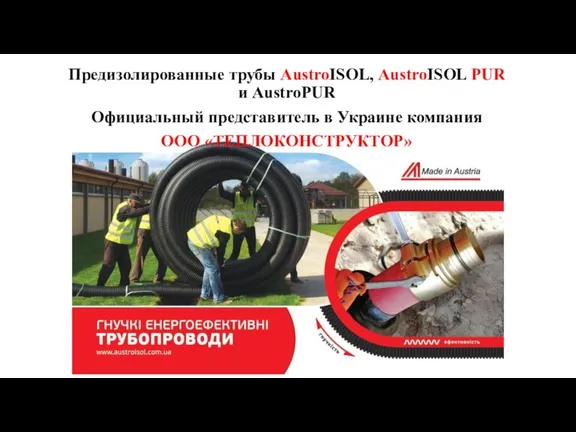 ООО Теплоконструктор