- 07 - Pulse Gen Assy Intro rev B sst

Содержание
- 2. © 2001, Halliburton Energy Services, Inc. January 12, 2001 Pulse Generator Assembly Objectives At the completion
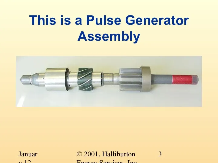
- 3. © 2001, Halliburton Energy Services, Inc. January 12, 2001 This is a Pulse Generator Assembly
- 4. © 2001, Halliburton Energy Services, Inc. January 12, 2001 What does a Pulse Generator Assembly do?
- 5. © 2001, Halliburton Energy Services, Inc. January 12, 2001 What makes a Pulse Generator Assembly The
- 6. © 2001, Halliburton Energy Services, Inc. January 12, 2001 What makes a Pulse Generator Assembly The
- 7. © 2001, Halliburton Energy Services, Inc. January 12, 2001 The Pulser
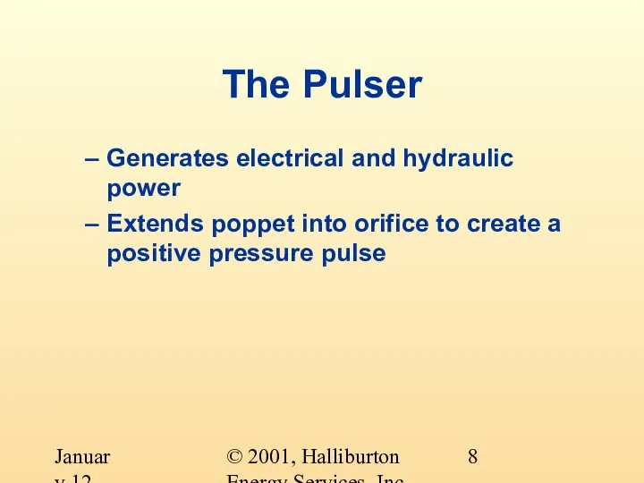
- 8. © 2001, Halliburton Energy Services, Inc. January 12, 2001 The Pulser Generates electrical and hydraulic power
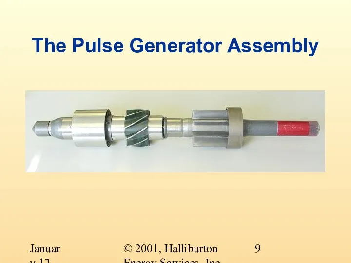
- 9. © 2001, Halliburton Energy Services, Inc. January 12, 2001 The Pulse Generator Assembly
- 10. © 2001, Halliburton Energy Services, Inc. January 12, 2001 The Flowgear Most of the flowgear comes
- 11. © 2001, Halliburton Energy Services, Inc. January 12, 2001 Pulse Generator Assembly The four systems can
- 12. © 2001, Halliburton Energy Services, Inc. January 12, 2001 Pulse Generator Assembly 1200 and 650 Systems
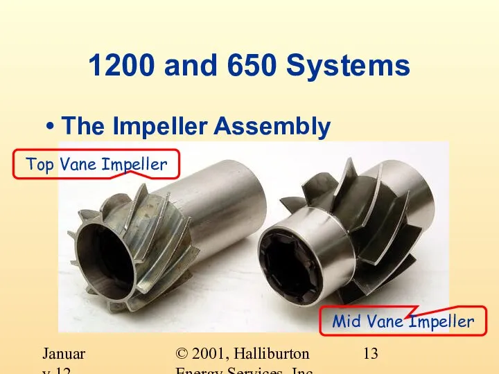
- 13. © 2001, Halliburton Energy Services, Inc. January 12, 2001 1200 and 650 Systems The Impeller Assembly
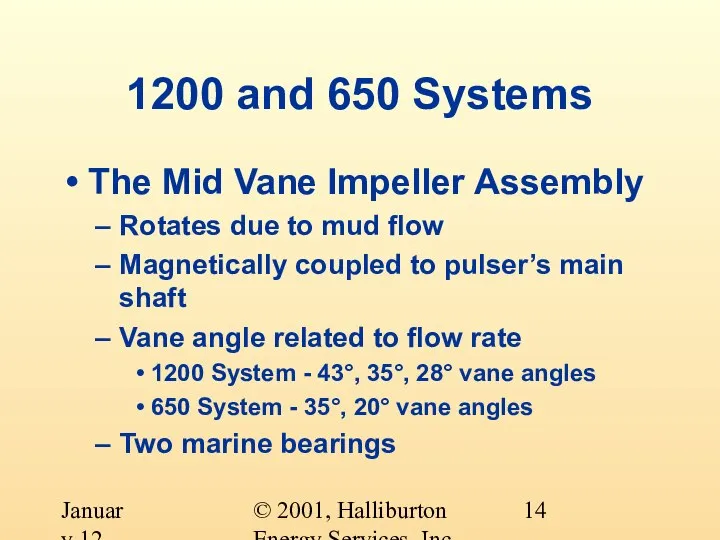
- 14. © 2001, Halliburton Energy Services, Inc. January 12, 2001 1200 and 650 Systems The Mid Vane
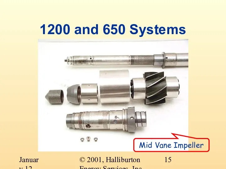
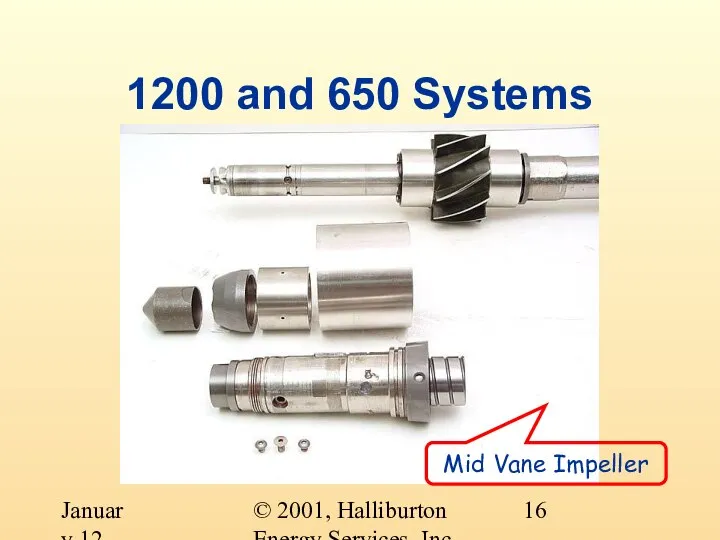
- 15. © 2001, Halliburton Energy Services, Inc. January 12, 2001 1200 and 650 Systems Mid Vane Impeller
- 16. © 2001, Halliburton Energy Services, Inc. January 12, 2001 1200 and 650 Systems Mid Vane Impeller
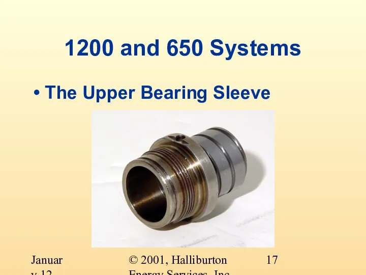
- 17. © 2001, Halliburton Energy Services, Inc. January 12, 2001 1200 and 650 Systems The Upper Bearing
- 18. © 2001, Halliburton Energy Services, Inc. January 12, 2001 1200 and 650 Systems The Upper Bearing
- 19. © 2001, Halliburton Energy Services, Inc. January 12, 2001 1200 and 650 Systems The Flow Diverter
- 20. © 2001, Halliburton Energy Services, Inc. January 12, 2001 1200 and 650 Systems The Flow Diverter
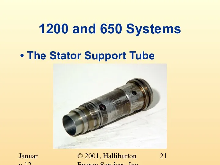
- 21. © 2001, Halliburton Energy Services, Inc. January 12, 2001 1200 and 650 Systems The Stator Support
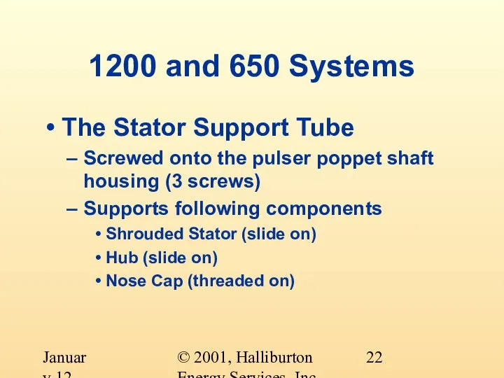
- 22. © 2001, Halliburton Energy Services, Inc. January 12, 2001 1200 and 650 Systems The Stator Support
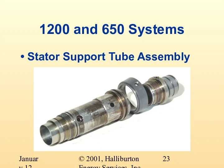
- 23. © 2001, Halliburton Energy Services, Inc. January 12, 2001 1200 and 650 Systems Stator Support Tube
- 24. © 2001, Halliburton Energy Services, Inc. January 12, 2001 1200 and 650 Systems Stator Support Tube
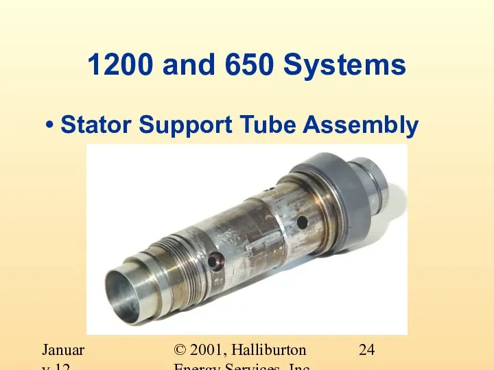
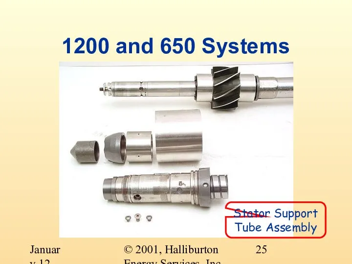
- 25. © 2001, Halliburton Energy Services, Inc. January 12, 2001 1200 and 650 Systems Stator Support Tube
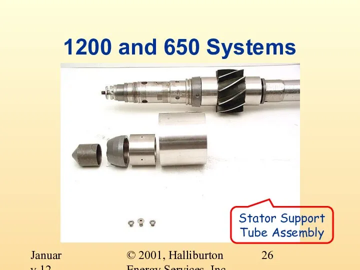
- 26. © 2001, Halliburton Energy Services, Inc. January 12, 2001 1200 and 650 Systems Stator Support Tube
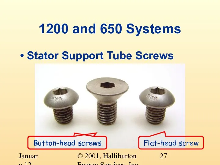
- 27. © 2001, Halliburton Energy Services, Inc. January 12, 2001 1200 and 650 Systems Stator Support Tube
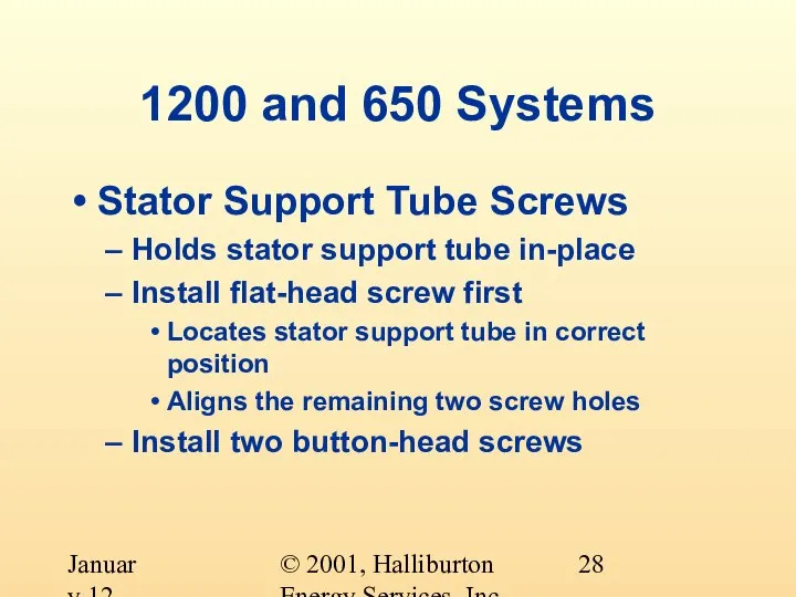
- 28. © 2001, Halliburton Energy Services, Inc. January 12, 2001 1200 and 650 Systems Stator Support Tube
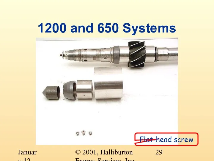
- 29. © 2001, Halliburton Energy Services, Inc. January 12, 2001 1200 and 650 Systems Flat-head screw
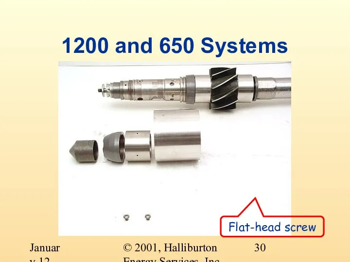
- 30. © 2001, Halliburton Energy Services, Inc. January 12, 2001 1200 and 650 Systems Flat-head screw
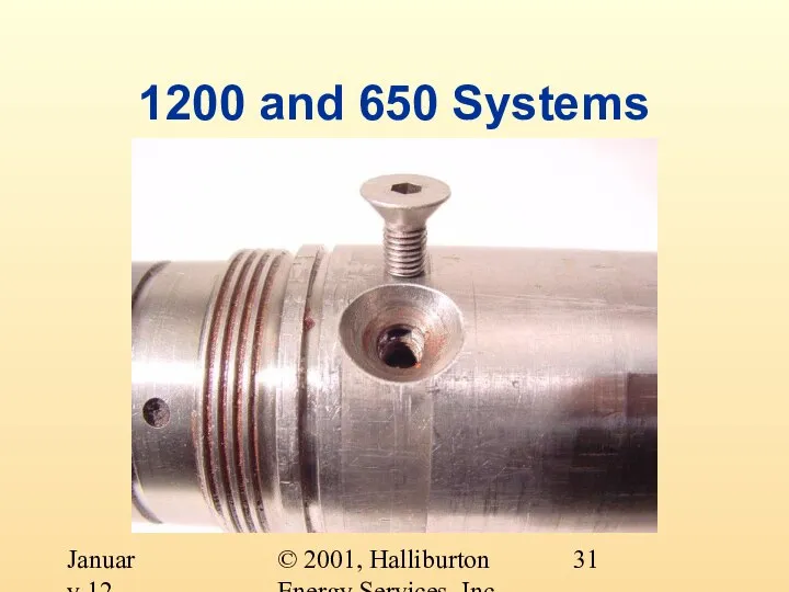
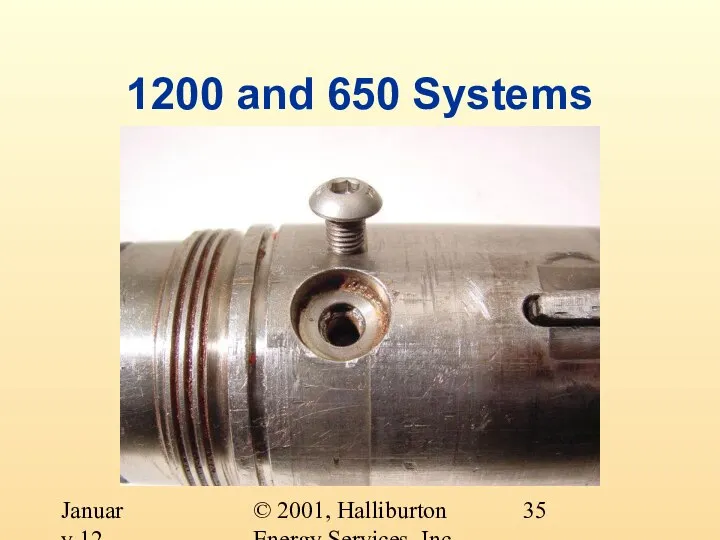
- 31. © 2001, Halliburton Energy Services, Inc. January 12, 2001 1200 and 650 Systems
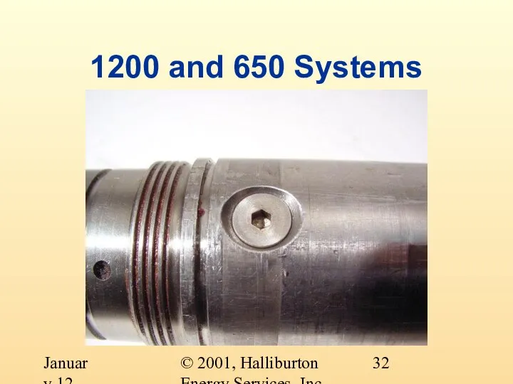
- 32. © 2001, Halliburton Energy Services, Inc. January 12, 2001 1200 and 650 Systems
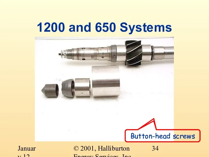
- 33. © 2001, Halliburton Energy Services, Inc. January 12, 2001 1200 and 650 Systems Button-head screws
- 34. © 2001, Halliburton Energy Services, Inc. January 12, 2001 1200 and 650 Systems Button-head screws Button-head
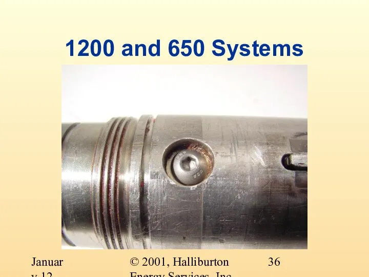
- 35. © 2001, Halliburton Energy Services, Inc. January 12, 2001 1200 and 650 Systems
- 36. © 2001, Halliburton Energy Services, Inc. January 12, 2001 1200 and 650 Systems
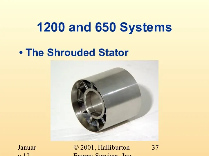
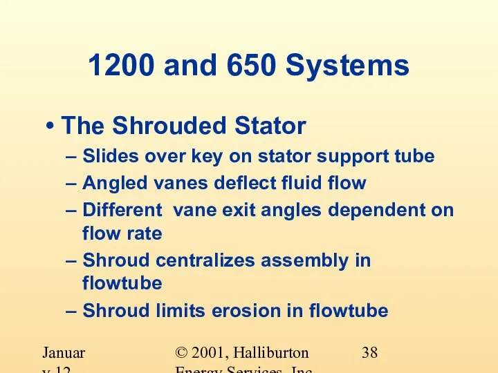
- 37. © 2001, Halliburton Energy Services, Inc. January 12, 2001 1200 and 650 Systems The Shrouded Stator
- 38. © 2001, Halliburton Energy Services, Inc. January 12, 2001 1200 and 650 Systems The Shrouded Stator
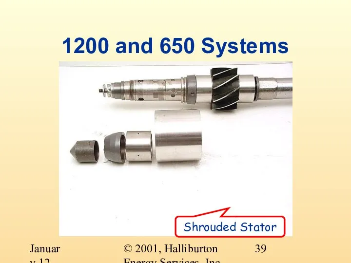
- 39. © 2001, Halliburton Energy Services, Inc. January 12, 2001 1200 and 650 Systems Shrouded Stator
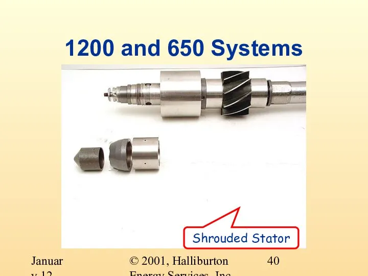
- 40. © 2001, Halliburton Energy Services, Inc. January 12, 2001 1200 and 650 Systems Shrouded Stator
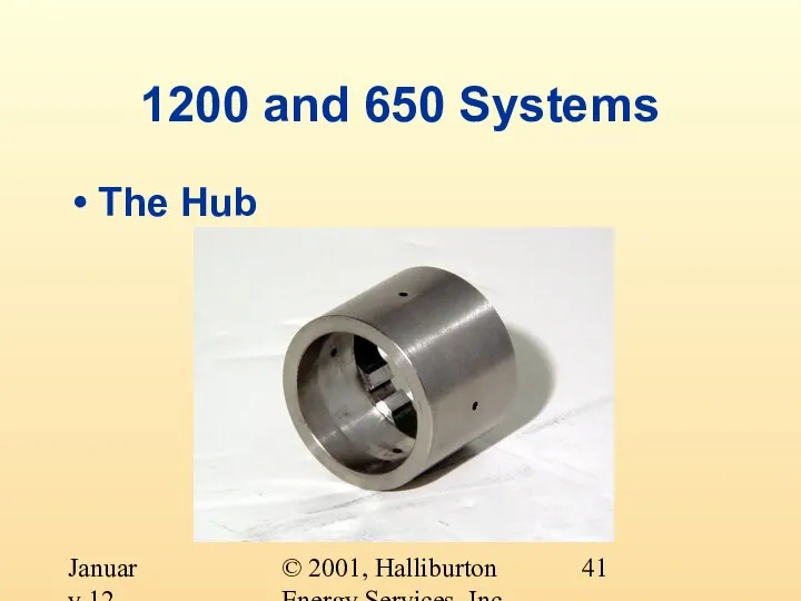
- 41. © 2001, Halliburton Energy Services, Inc. January 12, 2001 1200 and 650 Systems The Hub
- 42. © 2001, Halliburton Energy Services, Inc. January 12, 2001 1200 and 650 Systems The Hub Slides
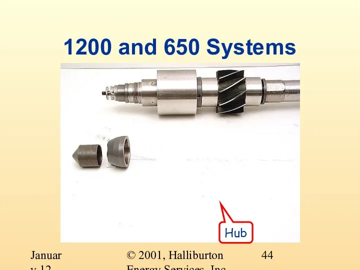
- 43. © 2001, Halliburton Energy Services, Inc. January 12, 2001 1200 and 650 Systems Hub
- 44. © 2001, Halliburton Energy Services, Inc. January 12, 2001 1200 and 650 Systems Hub
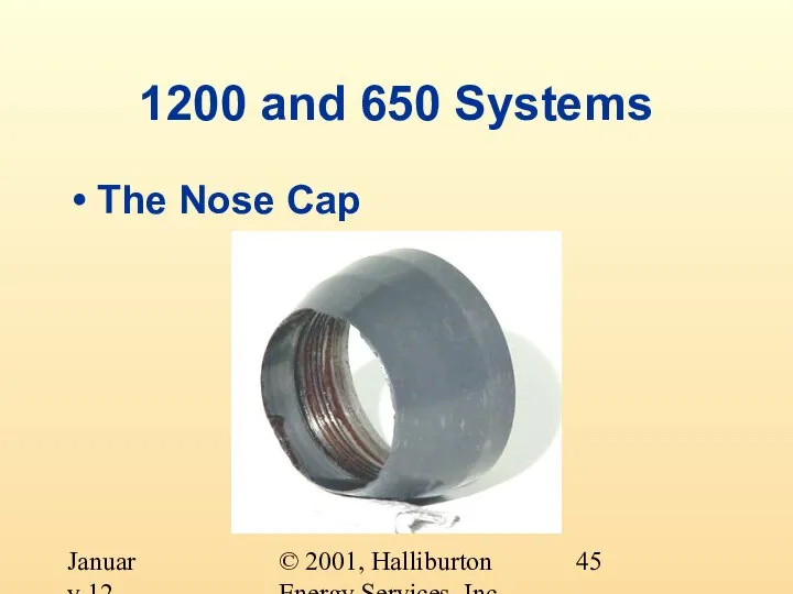
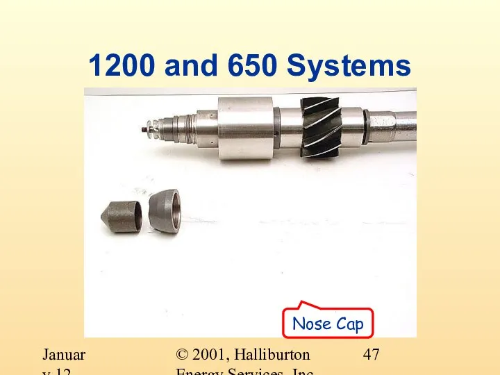
- 45. © 2001, Halliburton Energy Services, Inc. January 12, 2001 1200 and 650 Systems The Nose Cap
- 46. © 2001, Halliburton Energy Services, Inc. January 12, 2001 1200 and 650 Systems The Nose Cap
- 47. © 2001, Halliburton Energy Services, Inc. January 12, 2001 1200 and 650 Systems Nose Cap
- 48. © 2001, Halliburton Energy Services, Inc. January 12, 2001 1200 and 650 Systems Nose Cap
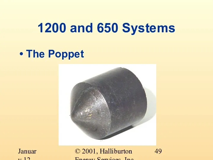
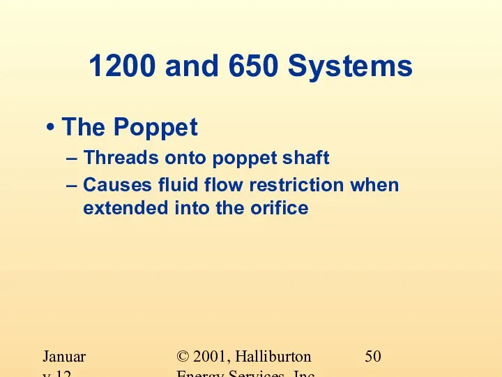
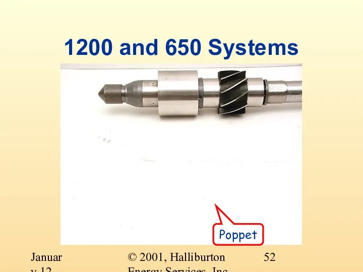
- 49. © 2001, Halliburton Energy Services, Inc. January 12, 2001 1200 and 650 Systems The Poppet
- 50. © 2001, Halliburton Energy Services, Inc. January 12, 2001 1200 and 650 Systems The Poppet Threads
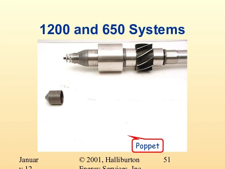
- 51. © 2001, Halliburton Energy Services, Inc. January 12, 2001 1200 and 650 Systems Poppet
- 52. © 2001, Halliburton Energy Services, Inc. January 12, 2001 1200 and 650 Systems Poppet
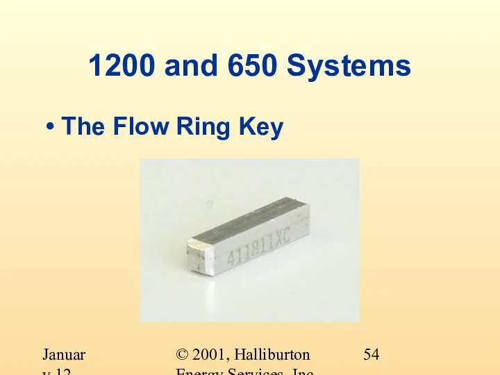
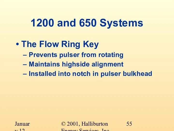
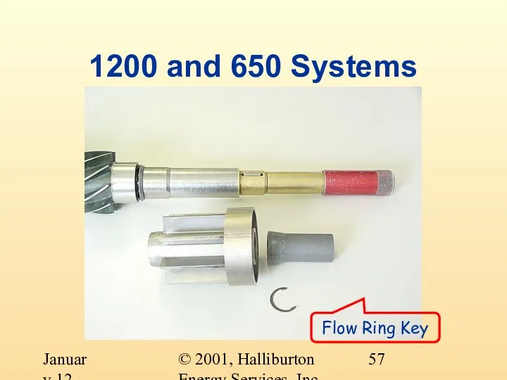
- 53. © 2001, Halliburton Energy Services, Inc. January 12, 2001 1200 and 650 Systems Flow Ring Key
- 54. © 2001, Halliburton Energy Services, Inc. January 12, 2001 1200 and 650 Systems The Flow Ring
- 55. © 2001, Halliburton Energy Services, Inc. January 12, 2001 1200 and 650 Systems The Flow Ring
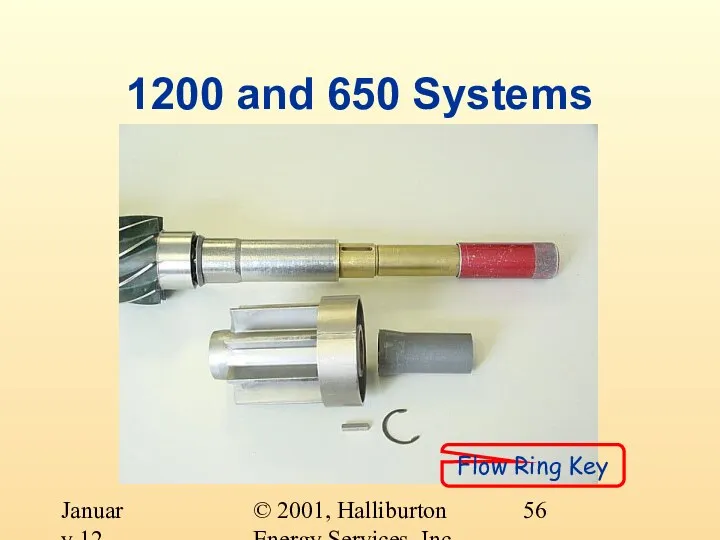
- 56. © 2001, Halliburton Energy Services, Inc. January 12, 2001 1200 and 650 Systems Flow Ring Key
- 57. © 2001, Halliburton Energy Services, Inc. January 12, 2001 1200 and 650 Systems Flow Ring Key
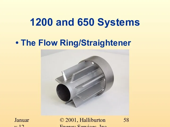
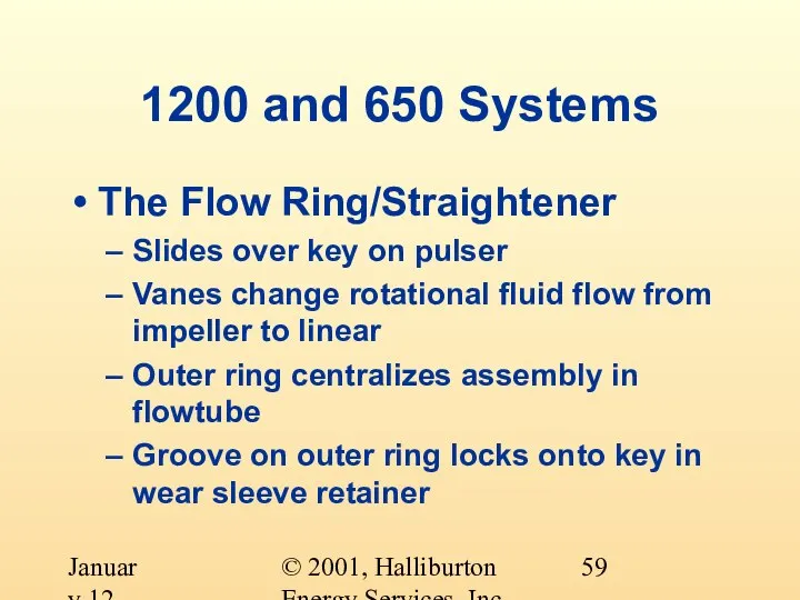
- 58. © 2001, Halliburton Energy Services, Inc. January 12, 2001 1200 and 650 Systems The Flow Ring/Straightener
- 59. © 2001, Halliburton Energy Services, Inc. January 12, 2001 1200 and 650 Systems The Flow Ring/Straightener
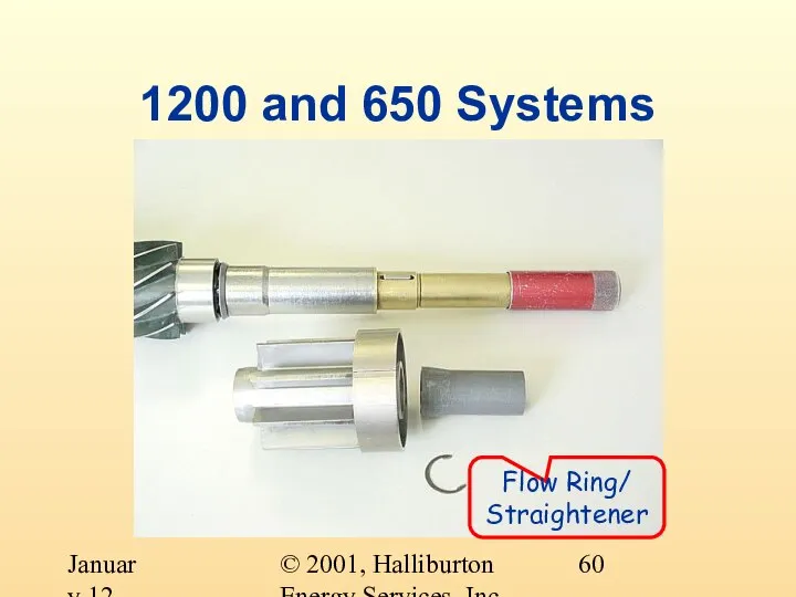
- 60. © 2001, Halliburton Energy Services, Inc. January 12, 2001 1200 and 650 Systems Flow Ring/ Straightener
- 61. © 2001, Halliburton Energy Services, Inc. January 12, 2001 1200 and 650 Systems Flow Ring/ Straightener
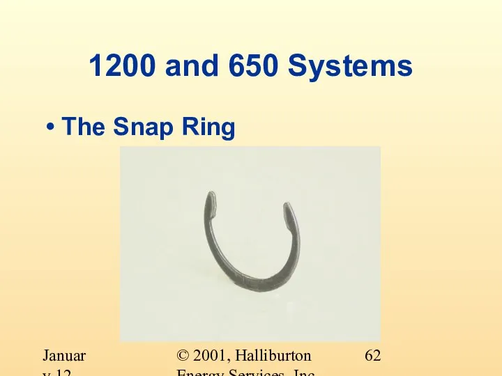
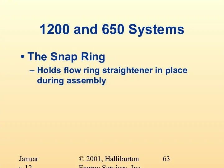
- 62. © 2001, Halliburton Energy Services, Inc. January 12, 2001 1200 and 650 Systems The Snap Ring
- 63. © 2001, Halliburton Energy Services, Inc. January 12, 2001 1200 and 650 Systems The Snap Ring
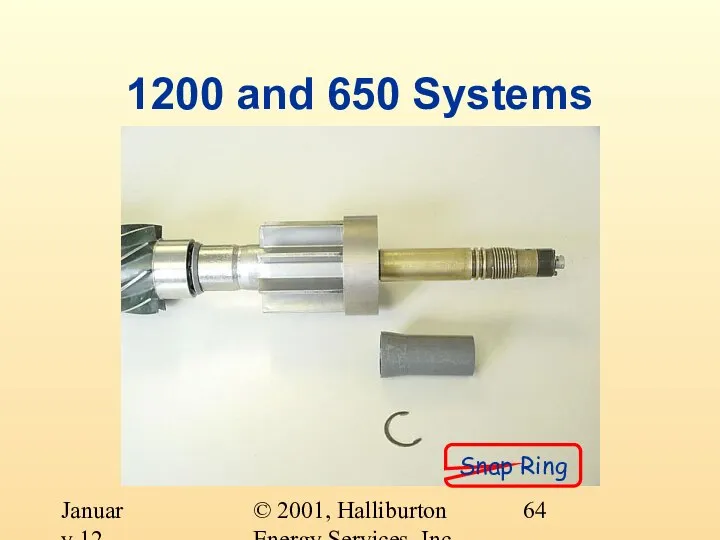
- 64. © 2001, Halliburton Energy Services, Inc. January 12, 2001 1200 and 650 Systems Snap Ring
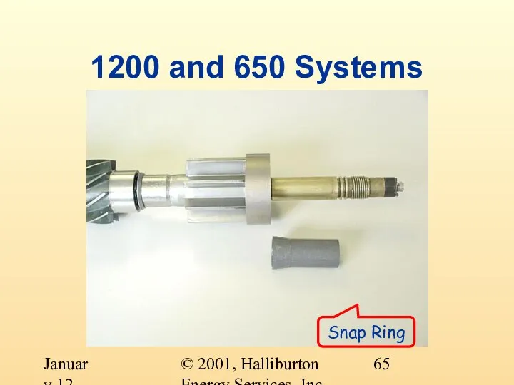
- 65. © 2001, Halliburton Energy Services, Inc. January 12, 2001 1200 and 650 Systems Snap Ring
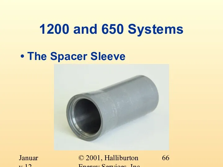
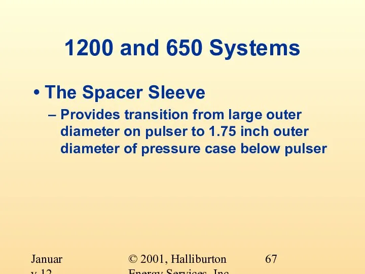
- 66. © 2001, Halliburton Energy Services, Inc. January 12, 2001 1200 and 650 Systems The Spacer Sleeve
- 67. © 2001, Halliburton Energy Services, Inc. January 12, 2001 1200 and 650 Systems The Spacer Sleeve
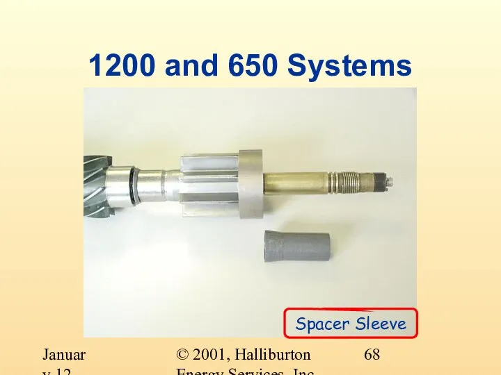
- 68. © 2001, Halliburton Energy Services, Inc. January 12, 2001 1200 and 650 Systems Spacer Sleeve
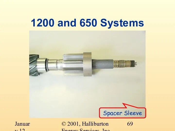
- 69. © 2001, Halliburton Energy Services, Inc. January 12, 2001 1200 and 650 Systems Spacer Sleeve
- 71. Скачать презентацию
Слайд 2© 2001, Halliburton Energy Services, Inc.
January 12, 2001
Pulse Generator Assembly Objectives
At the
© 2001, Halliburton Energy Services, Inc.
January 12, 2001
Pulse Generator Assembly Objectives
At the
Слайд 3© 2001, Halliburton Energy Services, Inc.
January 12, 2001
This is a Pulse Generator
© 2001, Halliburton Energy Services, Inc.
January 12, 2001
This is a Pulse Generator
Слайд 4© 2001, Halliburton Energy Services, Inc.
January 12, 2001
What does a Pulse Generator
© 2001, Halliburton Energy Services, Inc.
January 12, 2001
What does a Pulse Generator
Слайд 5© 2001, Halliburton Energy Services, Inc.
January 12, 2001
What makes a Pulse Generator
© 2001, Halliburton Energy Services, Inc.
January 12, 2001
What makes a Pulse Generator
Слайд 6© 2001, Halliburton Energy Services, Inc.
January 12, 2001
What makes a Pulse Generator
© 2001, Halliburton Energy Services, Inc.
January 12, 2001
What makes a Pulse Generator

Слайд 7© 2001, Halliburton Energy Services, Inc.
January 12, 2001
The Pulser
© 2001, Halliburton Energy Services, Inc.
January 12, 2001
The Pulser

Слайд 8© 2001, Halliburton Energy Services, Inc.
January 12, 2001
The Pulser
Generates electrical and hydraulic
© 2001, Halliburton Energy Services, Inc.
January 12, 2001
The Pulser
Generates electrical and hydraulic
Слайд 9© 2001, Halliburton Energy Services, Inc.
January 12, 2001
The Pulse Generator Assembly
© 2001, Halliburton Energy Services, Inc.
January 12, 2001
The Pulse Generator Assembly
Слайд 10© 2001, Halliburton Energy Services, Inc.
January 12, 2001
The Flowgear
Most of the flowgear
© 2001, Halliburton Energy Services, Inc.
January 12, 2001
The Flowgear
Most of the flowgear
Слайд 11© 2001, Halliburton Energy Services, Inc.
January 12, 2001
Pulse Generator Assembly
The four systems
© 2001, Halliburton Energy Services, Inc.
January 12, 2001
Pulse Generator Assembly
The four systems
Слайд 12© 2001, Halliburton Energy Services, Inc.
January 12, 2001
Pulse Generator Assembly
1200 and 650
© 2001, Halliburton Energy Services, Inc.
January 12, 2001
Pulse Generator Assembly
1200 and 650
Слайд 13© 2001, Halliburton Energy Services, Inc.
January 12, 2001
1200 and 650 Systems
The Impeller
© 2001, Halliburton Energy Services, Inc.
January 12, 2001
1200 and 650 Systems
The Impeller
Слайд 14© 2001, Halliburton Energy Services, Inc.
January 12, 2001
1200 and 650 Systems
The Mid
© 2001, Halliburton Energy Services, Inc.
January 12, 2001
1200 and 650 Systems
The Mid
Слайд 15© 2001, Halliburton Energy Services, Inc.
January 12, 2001
1200 and 650 Systems
Mid Vane
© 2001, Halliburton Energy Services, Inc.
January 12, 2001
1200 and 650 Systems
Mid Vane
Слайд 16© 2001, Halliburton Energy Services, Inc.
January 12, 2001
1200 and 650 Systems
Mid Vane
© 2001, Halliburton Energy Services, Inc.
January 12, 2001
1200 and 650 Systems
Mid Vane
Слайд 17© 2001, Halliburton Energy Services, Inc.
January 12, 2001
1200 and 650 Systems
The Upper
© 2001, Halliburton Energy Services, Inc.
January 12, 2001
1200 and 650 Systems
The Upper
Слайд 18© 2001, Halliburton Energy Services, Inc.
January 12, 2001
1200 and 650 Systems
The Upper
© 2001, Halliburton Energy Services, Inc.
January 12, 2001
1200 and 650 Systems
The Upper
Слайд 19© 2001, Halliburton Energy Services, Inc.
January 12, 2001
1200 and 650 Systems
The Flow
© 2001, Halliburton Energy Services, Inc.
January 12, 2001
1200 and 650 Systems
The Flow

Слайд 20© 2001, Halliburton Energy Services, Inc.
January 12, 2001
1200 and 650 Systems
The Flow
© 2001, Halliburton Energy Services, Inc.
January 12, 2001
1200 and 650 Systems
The Flow
Слайд 21© 2001, Halliburton Energy Services, Inc.
January 12, 2001
1200 and 650 Systems
The Stator
© 2001, Halliburton Energy Services, Inc.
January 12, 2001
1200 and 650 Systems
The Stator
Слайд 22© 2001, Halliburton Energy Services, Inc.
January 12, 2001
1200 and 650 Systems
The Stator
© 2001, Halliburton Energy Services, Inc.
January 12, 2001
1200 and 650 Systems
The Stator
Слайд 23© 2001, Halliburton Energy Services, Inc.
January 12, 2001
1200 and 650 Systems
Stator Support
© 2001, Halliburton Energy Services, Inc.
January 12, 2001
1200 and 650 Systems
Stator Support
Слайд 24© 2001, Halliburton Energy Services, Inc.
January 12, 2001
1200 and 650 Systems
Stator Support
© 2001, Halliburton Energy Services, Inc.
January 12, 2001
1200 and 650 Systems
Stator Support
Слайд 25© 2001, Halliburton Energy Services, Inc.
January 12, 2001
1200 and 650 Systems
Stator Support
Tube
© 2001, Halliburton Energy Services, Inc.
January 12, 2001
1200 and 650 Systems
Stator Support
Tube
Слайд 26© 2001, Halliburton Energy Services, Inc.
January 12, 2001
1200 and 650 Systems
Stator Support
Tube
© 2001, Halliburton Energy Services, Inc.
January 12, 2001
1200 and 650 Systems
Stator Support
Tube
Слайд 27© 2001, Halliburton Energy Services, Inc.
January 12, 2001
1200 and 650 Systems
Stator Support
© 2001, Halliburton Energy Services, Inc.
January 12, 2001
1200 and 650 Systems
Stator Support
Слайд 28© 2001, Halliburton Energy Services, Inc.
January 12, 2001
1200 and 650 Systems
Stator Support
© 2001, Halliburton Energy Services, Inc.
January 12, 2001
1200 and 650 Systems
Stator Support
Слайд 29© 2001, Halliburton Energy Services, Inc.
January 12, 2001
1200 and 650 Systems
Flat-head screw
© 2001, Halliburton Energy Services, Inc.
January 12, 2001
1200 and 650 Systems
Flat-head screw
Слайд 30© 2001, Halliburton Energy Services, Inc.
January 12, 2001
1200 and 650 Systems
Flat-head screw
© 2001, Halliburton Energy Services, Inc.
January 12, 2001
1200 and 650 Systems
Flat-head screw
Слайд 31© 2001, Halliburton Energy Services, Inc.
January 12, 2001
1200 and 650 Systems
© 2001, Halliburton Energy Services, Inc.
January 12, 2001
1200 and 650 Systems
Слайд 32© 2001, Halliburton Energy Services, Inc.
January 12, 2001
1200 and 650 Systems
© 2001, Halliburton Energy Services, Inc.
January 12, 2001
1200 and 650 Systems
Слайд 33© 2001, Halliburton Energy Services, Inc.
January 12, 2001
1200 and 650 Systems
Button-head screws
© 2001, Halliburton Energy Services, Inc.
January 12, 2001
1200 and 650 Systems
Button-head screws

Слайд 34© 2001, Halliburton Energy Services, Inc.
January 12, 2001
1200 and 650 Systems
Button-head screws
Button-head
© 2001, Halliburton Energy Services, Inc.
January 12, 2001
1200 and 650 Systems
Button-head screws
Button-head
Слайд 35© 2001, Halliburton Energy Services, Inc.
January 12, 2001
1200 and 650 Systems
© 2001, Halliburton Energy Services, Inc.
January 12, 2001
1200 and 650 Systems
Слайд 36© 2001, Halliburton Energy Services, Inc.
January 12, 2001
1200 and 650 Systems
© 2001, Halliburton Energy Services, Inc.
January 12, 2001
1200 and 650 Systems
Слайд 37© 2001, Halliburton Energy Services, Inc.
January 12, 2001
1200 and 650 Systems
The Shrouded
© 2001, Halliburton Energy Services, Inc.
January 12, 2001
1200 and 650 Systems
The Shrouded
Слайд 38© 2001, Halliburton Energy Services, Inc.
January 12, 2001
1200 and 650 Systems
The Shrouded
© 2001, Halliburton Energy Services, Inc.
January 12, 2001
1200 and 650 Systems
The Shrouded
Слайд 39© 2001, Halliburton Energy Services, Inc.
January 12, 2001
1200 and 650 Systems
Shrouded Stator
© 2001, Halliburton Energy Services, Inc.
January 12, 2001
1200 and 650 Systems
Shrouded Stator
Слайд 40© 2001, Halliburton Energy Services, Inc.
January 12, 2001
1200 and 650 Systems
Shrouded Stator
© 2001, Halliburton Energy Services, Inc.
January 12, 2001
1200 and 650 Systems
Shrouded Stator
Слайд 41© 2001, Halliburton Energy Services, Inc.
January 12, 2001
1200 and 650 Systems
The Hub
© 2001, Halliburton Energy Services, Inc.
January 12, 2001
1200 and 650 Systems
The Hub
Слайд 42© 2001, Halliburton Energy Services, Inc.
January 12, 2001
1200 and 650 Systems
The Hub
Slides
© 2001, Halliburton Energy Services, Inc.
January 12, 2001
1200 and 650 Systems
The Hub
Slides
Слайд 43© 2001, Halliburton Energy Services, Inc.
January 12, 2001
1200 and 650 Systems
Hub
© 2001, Halliburton Energy Services, Inc.
January 12, 2001
1200 and 650 Systems
Hub

Слайд 44© 2001, Halliburton Energy Services, Inc.
January 12, 2001
1200 and 650 Systems
Hub
© 2001, Halliburton Energy Services, Inc.
January 12, 2001
1200 and 650 Systems
Hub
Слайд 45© 2001, Halliburton Energy Services, Inc.
January 12, 2001
1200 and 650 Systems
The Nose
© 2001, Halliburton Energy Services, Inc.
January 12, 2001
1200 and 650 Systems
The Nose
Слайд 46© 2001, Halliburton Energy Services, Inc.
January 12, 2001
1200 and 650 Systems
The Nose
© 2001, Halliburton Energy Services, Inc.
January 12, 2001
1200 and 650 Systems
The Nose
Слайд 47© 2001, Halliburton Energy Services, Inc.
January 12, 2001
1200 and 650 Systems
Nose Cap
© 2001, Halliburton Energy Services, Inc.
January 12, 2001
1200 and 650 Systems
Nose Cap
Слайд 48© 2001, Halliburton Energy Services, Inc.
January 12, 2001
1200 and 650 Systems
Nose Cap
© 2001, Halliburton Energy Services, Inc.
January 12, 2001
1200 and 650 Systems
Nose Cap

Слайд 49© 2001, Halliburton Energy Services, Inc.
January 12, 2001
1200 and 650 Systems
The Poppet
© 2001, Halliburton Energy Services, Inc.
January 12, 2001
1200 and 650 Systems
The Poppet
Слайд 50© 2001, Halliburton Energy Services, Inc.
January 12, 2001
1200 and 650 Systems
The Poppet
Threads
© 2001, Halliburton Energy Services, Inc.
January 12, 2001
1200 and 650 Systems
The Poppet
Threads
Слайд 51© 2001, Halliburton Energy Services, Inc.
January 12, 2001
1200 and 650 Systems
Poppet
© 2001, Halliburton Energy Services, Inc.
January 12, 2001
1200 and 650 Systems
Poppet
Слайд 52© 2001, Halliburton Energy Services, Inc.
January 12, 2001
1200 and 650 Systems
Poppet
© 2001, Halliburton Energy Services, Inc.
January 12, 2001
1200 and 650 Systems
Poppet
Слайд 53© 2001, Halliburton Energy Services, Inc.
January 12, 2001
1200 and 650 Systems
Flow Ring
© 2001, Halliburton Energy Services, Inc.
January 12, 2001
1200 and 650 Systems
Flow Ring

Слайд 54© 2001, Halliburton Energy Services, Inc.
January 12, 2001
1200 and 650 Systems
The Flow
© 2001, Halliburton Energy Services, Inc.
January 12, 2001
1200 and 650 Systems
The Flow
Слайд 55© 2001, Halliburton Energy Services, Inc.
January 12, 2001
1200 and 650 Systems
The Flow
© 2001, Halliburton Energy Services, Inc.
January 12, 2001
1200 and 650 Systems
The Flow
Слайд 56© 2001, Halliburton Energy Services, Inc.
January 12, 2001
1200 and 650 Systems
Flow Ring
© 2001, Halliburton Energy Services, Inc.
January 12, 2001
1200 and 650 Systems
Flow Ring
Слайд 57© 2001, Halliburton Energy Services, Inc.
January 12, 2001
1200 and 650 Systems
Flow Ring
© 2001, Halliburton Energy Services, Inc.
January 12, 2001
1200 and 650 Systems
Flow Ring
Слайд 58© 2001, Halliburton Energy Services, Inc.
January 12, 2001
1200 and 650 Systems
The Flow
© 2001, Halliburton Energy Services, Inc.
January 12, 2001
1200 and 650 Systems
The Flow
Слайд 59© 2001, Halliburton Energy Services, Inc.
January 12, 2001
1200 and 650 Systems
The Flow
© 2001, Halliburton Energy Services, Inc.
January 12, 2001
1200 and 650 Systems
The Flow
Слайд 60© 2001, Halliburton Energy Services, Inc.
January 12, 2001
1200 and 650 Systems
Flow Ring/
Straightener
© 2001, Halliburton Energy Services, Inc.
January 12, 2001
1200 and 650 Systems
Flow Ring/
Straightener
Слайд 61© 2001, Halliburton Energy Services, Inc.
January 12, 2001
1200 and 650 Systems
Flow Ring/
Straightener
© 2001, Halliburton Energy Services, Inc.
January 12, 2001
1200 and 650 Systems
Flow Ring/
Straightener

Слайд 62© 2001, Halliburton Energy Services, Inc.
January 12, 2001
1200 and 650 Systems
The Snap
© 2001, Halliburton Energy Services, Inc.
January 12, 2001
1200 and 650 Systems
The Snap
Слайд 63© 2001, Halliburton Energy Services, Inc.
January 12, 2001
1200 and 650 Systems
The Snap
© 2001, Halliburton Energy Services, Inc.
January 12, 2001
1200 and 650 Systems
The Snap
Слайд 64© 2001, Halliburton Energy Services, Inc.
January 12, 2001
1200 and 650 Systems
Snap Ring
© 2001, Halliburton Energy Services, Inc.
January 12, 2001
1200 and 650 Systems
Snap Ring
Слайд 65© 2001, Halliburton Energy Services, Inc.
January 12, 2001
1200 and 650 Systems
Snap Ring
© 2001, Halliburton Energy Services, Inc.
January 12, 2001
1200 and 650 Systems
Snap Ring
Слайд 66© 2001, Halliburton Energy Services, Inc.
January 12, 2001
1200 and 650 Systems
The Spacer
© 2001, Halliburton Energy Services, Inc.
January 12, 2001
1200 and 650 Systems
The Spacer
Слайд 67© 2001, Halliburton Energy Services, Inc.
January 12, 2001
1200 and 650 Systems
The Spacer
© 2001, Halliburton Energy Services, Inc.
January 12, 2001
1200 and 650 Systems
The Spacer
Слайд 68© 2001, Halliburton Energy Services, Inc.
January 12, 2001
1200 and 650 Systems
Spacer Sleeve
© 2001, Halliburton Energy Services, Inc.
January 12, 2001
1200 and 650 Systems
Spacer Sleeve
Слайд 69© 2001, Halliburton Energy Services, Inc.
January 12, 2001
1200 and 650 Systems
Spacer Sleeve
© 2001, Halliburton Energy Services, Inc.
January 12, 2001
1200 and 650 Systems
Spacer Sleeve
 Все о полиграфическом рынке
 Компания Ракурс
 Эмпирические социальные достижения
  Как возникло франкское государство
 Сложение чисел с помощью координатной прямой
 Значение творчества В.А.Серова для развития отечественной живописи
 CIVIL LAW Concept and grounds
 Неополис - город будущего. Город на реке: бренд успешной столицы
 Магистральные модели
 Тонкослойная хроматография
 Презентация на тему Строение цветка
  Основные устройства компьютера,их функции и взаимосвязь.
 Молекулярная эволюция и филогенетика
  КОНДИЦИОНЕРЫ Samsung 2009
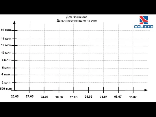 Пришедшая выручка
 Первобытные люди 4 класс
 Италия после второй мировой войны
 Магический кубик
 Закон о воспитании: план действий дошкольной организации по реализации новых положений законодательства
 d4798d3f5a007823a7d4b1743d3eced2
 Армянский Петербург
 НАЦИОНАЛЬНЫЙ ПЛАН УПРАВЛЕНИЯ ЗАСУХАМИ ПО ГРУЗИИ
 Презентация на тему Вакуумные приборы
  Тема лекции:«Электронная цифровая подпись»
 Электронный дневник и электронный журнал в NetSchool как часть комплексной информационной системы (с) 2001-2011 ИРТех
 А.С. Пушкин Краткая биография в картинках
 Перейти Рубикон
 Презентация на тему A history about David Livingstone