- Descriptive geometry

Содержание
- 2. Surfaces.
- 3. Surfaces. Classification. Determinant. Outline.
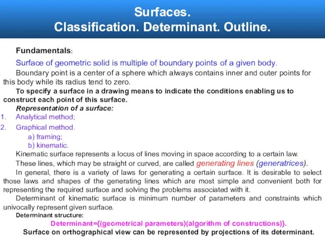
- 4. Surfaces. Classification. Determinant. Outline. Fundamentals: Surface of geometric solid is multiple of boundary points of a
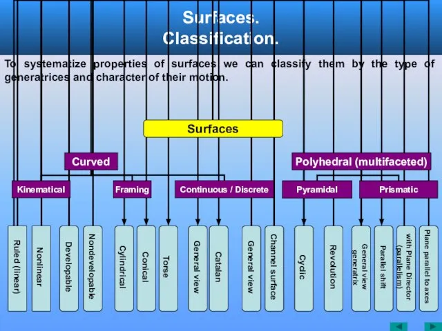
- 5. Surfaces. Classification. To systematize properties of surfaces we can classify them by the type of generatrices
- 6. Surfaces. Classification. Determinant. Outline. Outline of a Surface. For a surface to be specified, it is
- 7. Surfaces. Classification. Determinant. Outline. Outline of a Surface. П2 S Contour line Outline Projectors O1 O2
- 8. Surfaces. Classification. Determinant. Outline. Outline of a surface. Frontal Visible Contour Frontal Outline Horizontal Visible Contour
- 9. Surfaces of Revolution. Forming. Definitions. Parallel Meridian Generatrix Neck Axis of revolution l1 i m3 m2
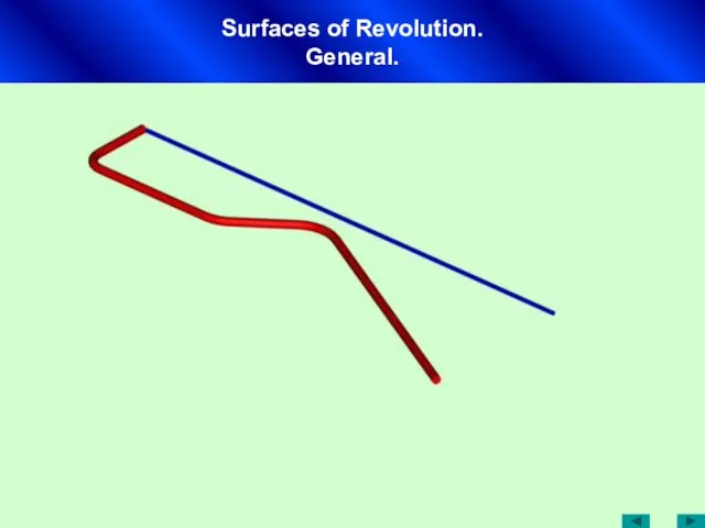
- 10. Surfaces of Revolution. General.
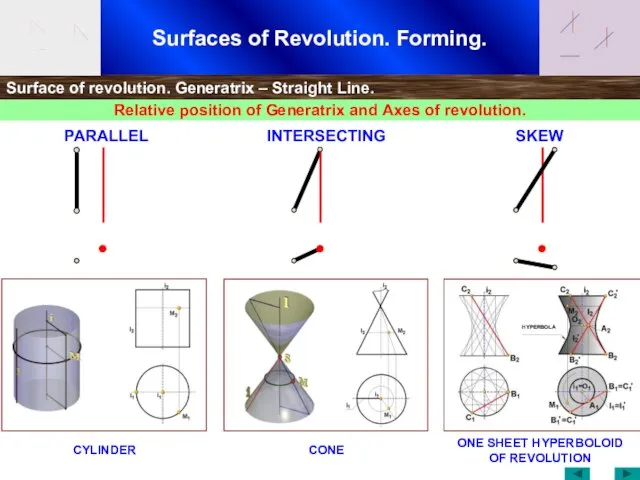
- 11. Surfaces of Revolution. Forming. Surface of revolution. Generatrix – Straight Line. Relative position of Generatrix and
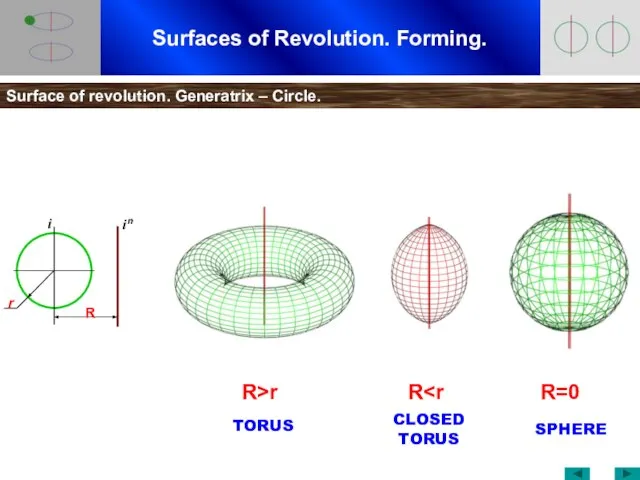
- 12. Surfaces of Revolution. Forming. Surface of revolution. Generatrix – Circle. R>r R R=0 TORUS CLOSED TORUS
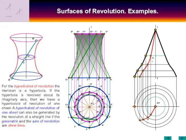
- 13. Surfaces of Revolution. Examples. 12' I I=I' 10'' 1' 2' 3' 4' 5' 6' 9'' 11''
- 14. Surfaces of Revolution. Examples. C O B I I' A B1 B2 A2 A1 B1 A2
- 15. Surfaces of Revolution. Sections by Planes. O1 42 32 22 12 (1)1 =31 (2)1 =41 11
- 16. Surfaces of Revolution. Sections by Planes. S ELLIPSE – TWO OUTLINES FROM ONE SIDE OF AN
- 17. Surfaces of Revolution. Sections by Planes. Point Ellipse Circle Double Parabola Parabola Two straight Lines Hyperbola
- 18. Surfaces of Revolution. Sections by Planes. A C B D D' B' C' O' A' B2
- 19. Surfaces of Revolution. Sections by Planes. O' M2 =N2 =O2 M' M' K2 J2 =L2 L'
- 20. Surfaces of Revolution. Sections by Planes. O' M2 =N2 =O2 M' M' K2 J2 =L2 L'
- 21. Sections of Solids. Designate all character points of intersection between cutting plane and surfaces of figure.
- 22. Intersection between a Solid and a Plane. Three ways how to construct conical section. 1. Using
- 23. Intersection between a Solid and a Plane. S1 (1)2 32 22 52 31 42 S2 21
- 24. Surfaces. Ruled surfaces. A surface which can be generated by a straight line is called the
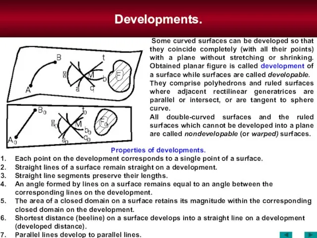
- 25. Surfaces. Developable Ruled surfaces. Some curved surfaces can be developed so that they coincide completely (with
- 26. Surfaces. Ruled surfaces with one Diretrix. Conical Surface m1 m2 A2 A S m M2 M1
- 27. Surfaces. Ruled surfaces with one Diretrix. Cylindrical surface A2 m2 m1 A1 m l1 A l
- 28. Surfaces. Ruled surfaces with one Diretrix. n, k – border lines l1 m1 B1 m2 l2
- 29. Surfaces. Ruled surfaces with one Diretrix. Beveled Gear surface Spur Gear surface
- 30. Surfaces. Ruled surfaces with two Diretrices. where, l— generatrix, m, n —directrices; σ — plane director.
- 31. Surfaces. Ruled surfaces with two Diretrices. CYLINDROID –– both directrices are curves. CONOID –– one directrix
- 32. Surfaces. Ruled surfaces with two Diretrices. σ2 – plane director. l1 l'1 m1 M1 l2 M2
- 33. Surfaces. Ruled surfaces with two Diretrices. σ2 - plane director. х m2 n1 m1 σ2 σ2
- 34. Surfaces. Ruled surfaces with two Diretrices. σ1 - plane director. σ1 х σ1 m2 M1 n2
- 35. Surfaces. Ruled surfaces with two Diretrices. WARPED PLANE –– both directrices are straight lines. x m2
- 36. Surfaces. Ruled surfaces with two Diretrices. Right Helicoid Right Helicoid — ruled surface with a plane
- 37. Surfaces. Ruled surfaces with two Diretrices. Skew Helicoid Skew Helicoid – ruled surface where generatrix ℓ
- 38. Surfaces. Ruled surfaces with two Diretrices. Right Helicoid Skew Helicoid
- 39. Surfaces. Ruled surfaces with three Diretrices. 1 – general view (3 directrices – curved lines) 2
- 40. Surfaces. Ruled surfaces with three Diretrices. One-sheet Hyperboloid — can be formed by moving straight line
- 41. Surfaces. Ruled surfaces with three Diretrices. Skew Wedge surface (type of double-skew cylindroid surface) — two
- 42. Channel Surfaces.
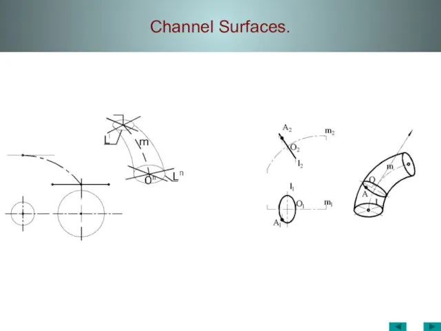
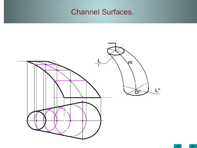
- 43. Channel Surfaces. On Ln L1 m
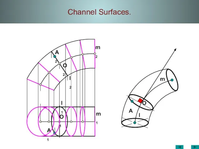
- 44. Channel Surfaces. A1 A m1 O1 l m2 l2 l1 O2 A2 O m
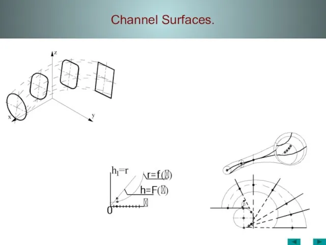
- 45. Channel Surfaces.
- 46. Channel Surfaces. Screw Torus
- 47. Surfaces. Positional problems. Intersection between a Line and a Surface. 1 11 21 2 12 22
- 48. Surfaces. Positional problems. Intersection between a Line and a Surface. M1 M2 A1 b2 A2 R1
- 49. Intersection between АВ-line and surface of revolution. Surfaces. Positional problems. Intersection between a Line and a
- 50. Surfaces. Positional problems. Intersection between a Line and a Surface. 8 12 N2 11 x M1
- 51. Surfaces. Positional problems. Intersection between a Line and a Surface. 10 a2 k2 a1 k1 h2
- 52. Surfaces. Positional problems. Intersection between a Line and a Surface. n1 12 m1 11 a1 21
- 53. Surfaces. Positional problems. Intersection between surfaces. Positional problems determine relative position and mutual belongings of objects
- 54. Intersection between Surfaces A2 A1 B2 C2 C1 B1 A3 =C3 B3 S2 S3 S1 12
- 55. Intersection between Surfaces. Y34 12 (2')2 (3')2 42 (5')2 (4')2 32 22 (1')2 52 11 41
- 56. МТК Intersection between Surfaces. Polyhedrons. Both Surfaces are perpendicular to principal planes
- 57. МТК Intersection between Surfaces. f2 h1 62 B1 22 32 42 52 72 f1 h2 11
- 58. Intersection between Surfaces. B2 A2 C2 C1 B1 A1 11 21 31 41 51 61 S1
- 59. Intersection between Surfaces. Cutting Surface Method. To construct curve of intersection between surfaces we can use
- 60. Intersection between Surfaces. Cutting Plane Method. S2 (2')2 (3')2 42 (5')2 (4')2 32 22 52 (4')3
- 61. Intersection between Surfaces.
- 62. Intersection between Surfaces. Cutting Plane Method. RC1 RC2 RК1 RК2 RC3
- 63. Intersection between Surfaces. Τ1 Γ2 21 11 42 32 Σ1 51 61 52 53 63 42
- 64. Intersection between Surfaces. Cutting Plane Method. а1 61 81 41 42 92 31 Σ1 Δ1=f1 72
- 65. Intersection between Surfaces. Cutting Sphere Method. Coaxial surfaces of revolution (i.e. surfaces with a common axis)
- 66. Intersection between Surfaces. Cutting Sphere Method. Cutting surfaces - spheres Theorem: Two coaxial surfaces of revolution
- 67. Intersection between Surfaces. Cutting Sphere Method. Algorithm how to construct curves of intersection between two surfaces
- 68. Intersection between Surfaces. Cutting Sphere Method. Cutting surfaces – eccentric spheres Algorithm how to construct curves
- 69. Intersection between Surfaces. Cutting Sphere Method. Curve of intersection Curve of intersection Concentric spheres Eccentric spheres
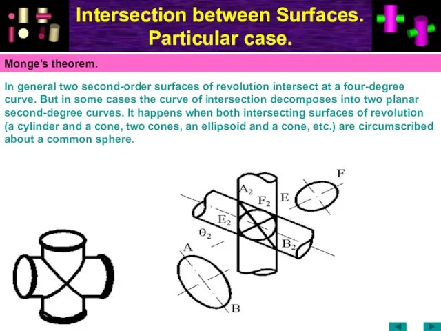
- 70. Intersection between Surfaces. Particular case. In general two second-order surfaces of revolution intersect at a four-degree
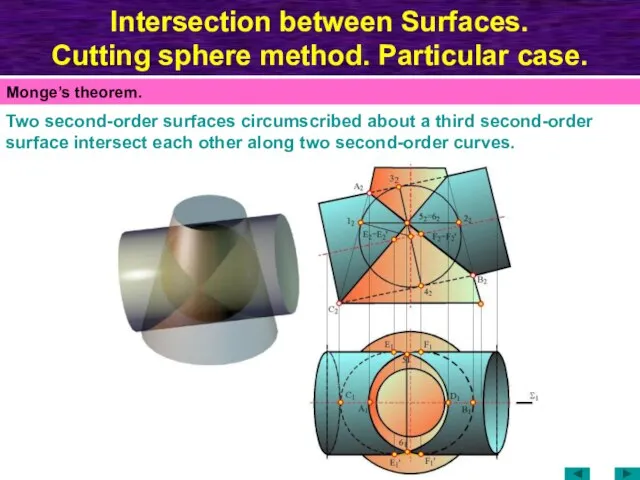
- 71. Intersection between Surfaces. Cutting sphere method. Particular case. Two second-order surfaces circumscribed about a third second-order
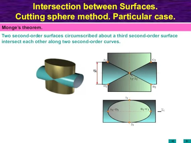
- 72. Intersection between Surfaces. Cutting sphere method. Particular case. Two second-order surfaces circumscribed about a third second-order
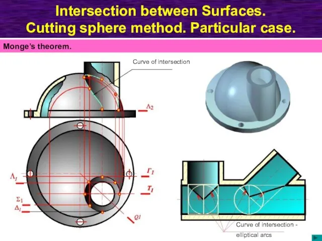
- 73. Intersection between Surfaces. Cutting sphere method. Particular case. Curve of intersection Curve of intersection - elliptical
- 74. Developments. Properties of developments. Each point on the development corresponds to a single point of a
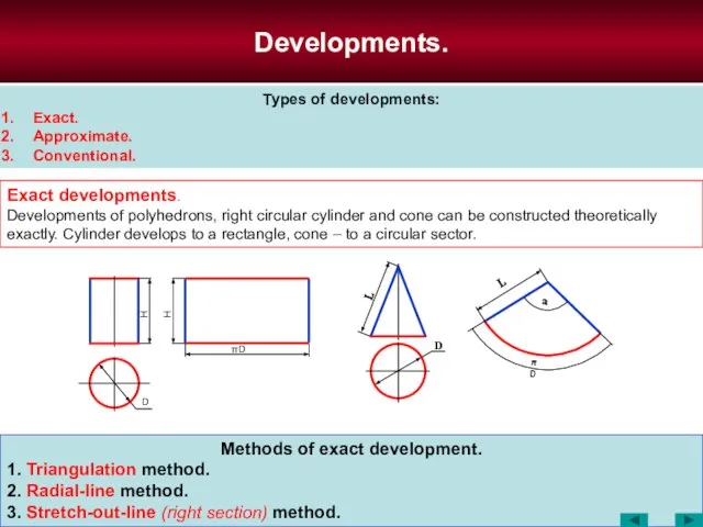
- 75. Methods of exact development. 1. Triangulation method. 2. Radial-line method. 3. Stretch-out-line (right section) method. Developments.
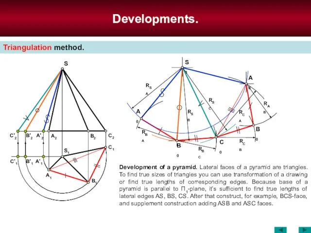
- 76. Developments. Triangulation method. Development of a pyramid. Lateral faces of a pyramid are triangles. To find
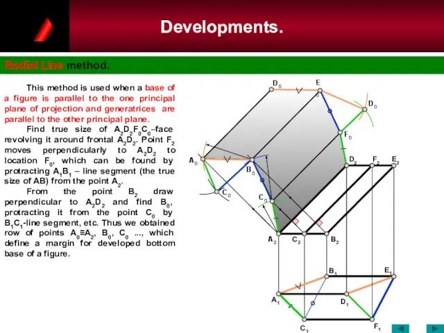
- 77. Developments. Radial Line method. C0 A1 A2 C0 A0 B0 D0 D1 C1 F1 B1 C2
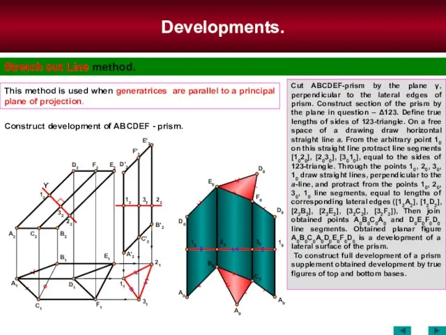
- 78. Developments. Stretch out Line method. This method is used when generatrices are parallel to a principal
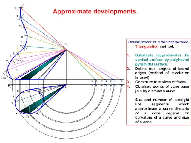
- 79. Development of a conical surface. Triangulation method. Substitute (approximate) the conical surface by polyhedral pyramidal surface.
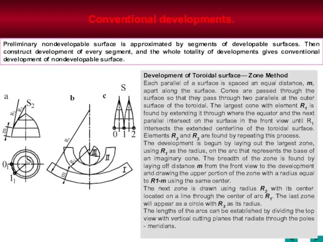
- 80. Conventional developments. Development of Toroidal surface— Zone Method Each parallel of a surface is spaced an
- 82. Скачать презентацию
Слайд 3Surfaces.
Classification. Determinant. Outline.
Surfaces.
Classification. Determinant. Outline.
Слайд 4Surfaces.
Classification. Determinant. Outline.
Fundamentals:
Surface of geometric solid is multiple of boundary
Surfaces.
Classification. Determinant. Outline.
Fundamentals:
Surface of geometric solid is multiple of boundary
Слайд 5Surfaces.
Classification.
To systematize properties of surfaces we can classify them by the
Surfaces.
Classification.
To systematize properties of surfaces we can classify them by the
Слайд 6Surfaces.
Classification. Determinant. Outline.
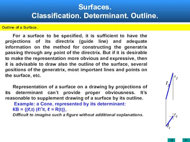
Outline of a Surface.
For a surface to be
Surfaces.
Classification. Determinant. Outline.
Outline of a Surface.
For a surface to be
Слайд 7Surfaces.
Classification. Determinant. Outline.
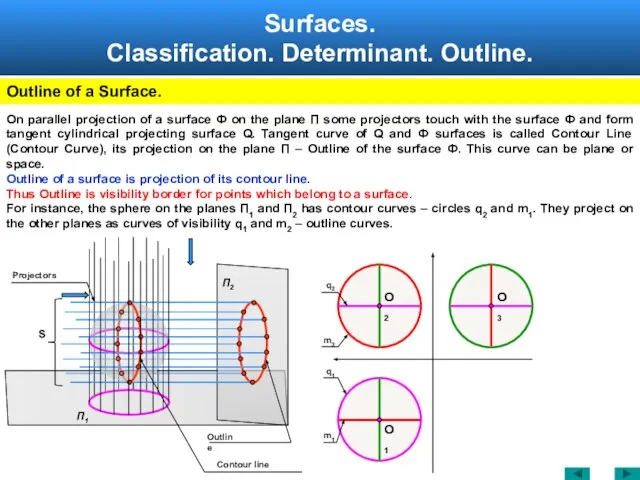
Outline of a Surface.
П2
S
Contour line
Outline
Projectors
O1
O2
O3
П1
On
Surfaces.
Classification. Determinant. Outline.
Outline of a Surface.
П2
S
Contour line
Outline
Projectors
O1
O2
O3
П1
On
Слайд 8Surfaces.
Classification. Determinant. Outline.
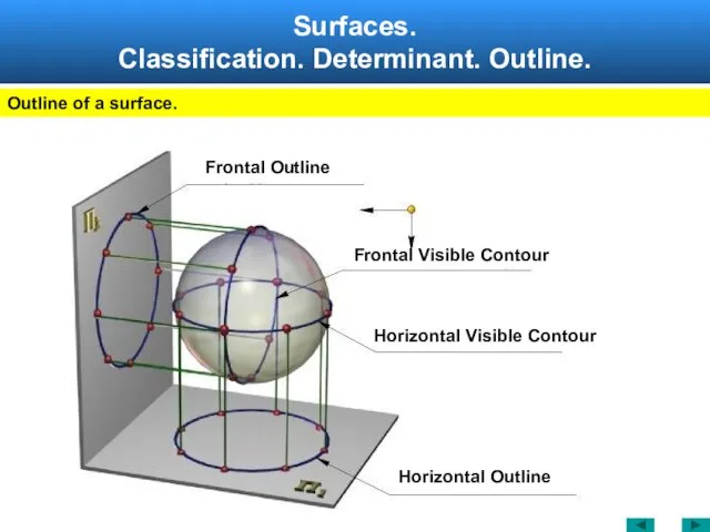
Outline of a surface.
Frontal Visible Contour
Frontal Outline
Horizontal Visible Contour
Horizontal
Surfaces.
Classification. Determinant. Outline.
Outline of a surface.
Frontal Visible Contour
Frontal Outline
Horizontal Visible Contour
Horizontal
Слайд 9Surfaces of Revolution. Forming.
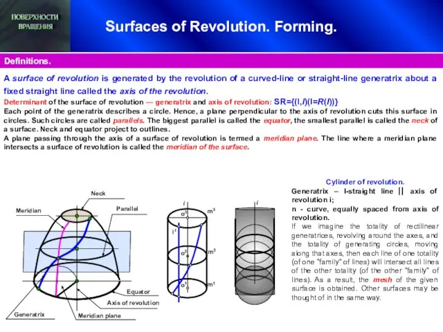
Definitions.
Parallel
Meridian
Generatrix
Neck
Axis of revolution
l1
i
m3
m2
m1
o2
o1
o3
i
Meridian plane
A surface of revolution is
Surfaces of Revolution. Forming.
Definitions.
Parallel
Meridian
Generatrix
Neck
Axis of revolution
l1
i
m3
m2
m1
o2
o1
o3
i
Meridian plane
A surface of revolution is
Слайд 10Surfaces of Revolution.
General.
Surfaces of Revolution.
General.
Слайд 11Surfaces of Revolution. Forming.
Surface of revolution. Generatrix – Straight Line.
Relative position of
Surfaces of Revolution. Forming.
Surface of revolution. Generatrix – Straight Line.
Relative position of
Слайд 12Surfaces of Revolution. Forming.
Surface of revolution. Generatrix – Circle.
R>r
RR=0
TORUS
CLOSED
Surfaces of Revolution. Forming.
Surface of revolution. Generatrix – Circle.
R>r
R R=0 TORUS CLOSED
Слайд 13Surfaces of Revolution. Examples.
12'
I
I=I'
10''
1'
2'
3'
4'
5'
6'
9''
11''
12''
1''
2''
3''
I=I'
m1
m2
I'
I
1'
12'
2'
11'
10'
9'
8'
3'
7'
6'
5'
4'
5''
4''
3''
2''
1''
6''
10''
9''
8''
7''
12''
11''
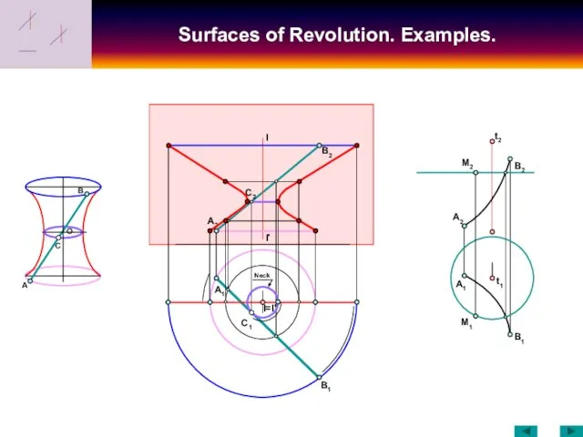
For the hyperboloid of revolution the meridian is a
Surfaces of Revolution. Examples.
12'
I
I=I'
10''
1'
2'
3'
4'
5'
6'
9''
11''
12''
1''
2''
3''
I=I'
m1
m2
I'
I
1'
12'
2'
11'
10'
9'
8'
3'
7'
6'
5'
4'
5''
4''
3''
2''
1''
6''
10''
9''
8''
7''
12''
11''
For the hyperboloid of revolution the meridian is a
Слайд 14Surfaces of Revolution. Examples.
C
O
B
I
I'
A
B1
B2
A2
A1
B1
A2
B2
M2
t1
t2
C2
I=I'
A1
C1
M1
Neck
Surfaces of Revolution. Examples.
C
O
B
I
I'
A
B1
B2
A2
A1
B1
A2
B2
M2
t1
t2
C2
I=I'
A1
C1
M1
Neck
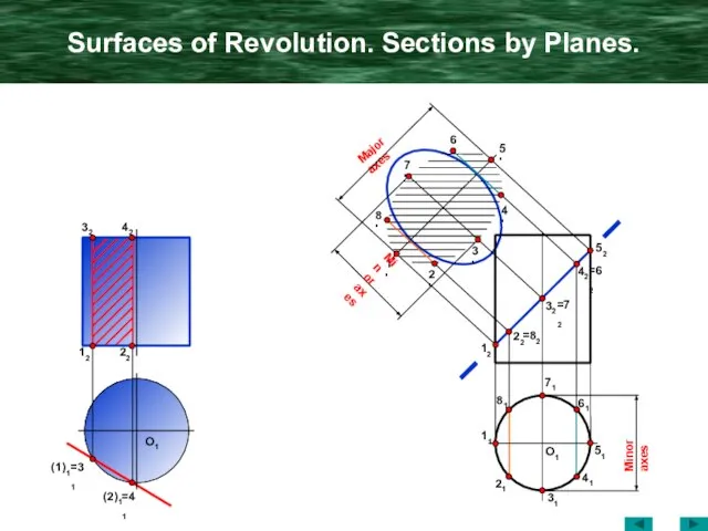
Слайд 15Surfaces of Revolution. Sections by Planes.
O1
42
32
22
12
(1)1
=31
(2)1
=41
11
81
21
31
41
51
61
71
12
22
=82
52
42
=62
32
=72
1'
2'
8'
3'
7'
4'
6'
5'
O1
Minor axes
Major axes
Minor axes
Surfaces of Revolution. Sections by Planes.
O1
42
32
22
12
(1)1
=31
(2)1
=41
11
81
21
31
41
51
61
71
12
22
=82
52
42
=62
32
=72
1'
2'
8'
3'
7'
4'
6'
5'
O1
Minor axes
Major axes
Minor axes
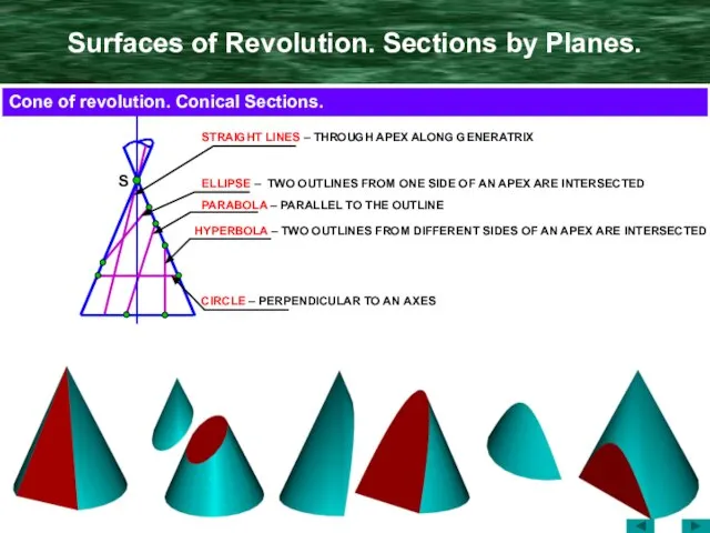
Слайд 16Surfaces of Revolution. Sections by Planes.
S
ELLIPSE – TWO OUTLINES FROM ONE SIDE
Surfaces of Revolution. Sections by Planes.
S
ELLIPSE – TWO OUTLINES FROM ONE SIDE
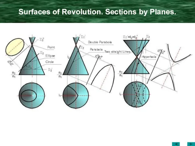
Слайд 17Surfaces of Revolution. Sections by Planes.
Point
Ellipse
Circle
Double Parabola
Parabola
Two straight Lines
Hyperbola
Surfaces of Revolution. Sections by Planes.
Point
Ellipse
Circle
Double Parabola
Parabola
Two straight Lines
Hyperbola
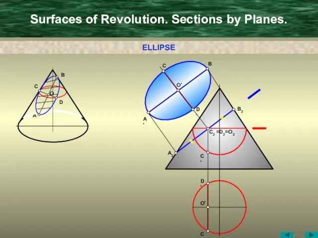
Слайд 18Surfaces of Revolution. Sections by Planes.
A
C
B
D
D'
B'
C'
O'
A'
B2
=D2
=O2
C2
C'
A2
C'
D'
O'
O
ELLIPSE
Surfaces of Revolution. Sections by Planes.
A
C
B
D
D'
B'
C'
O'
A'
B2
=D2
=O2
C2
C'
A2
C'
D'
O'
O
ELLIPSE
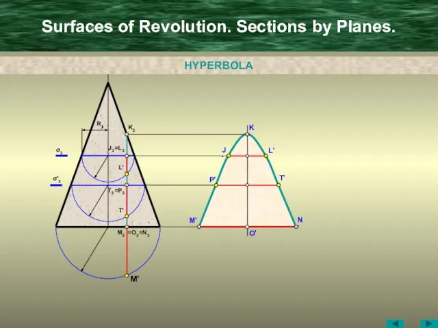
Слайд 19Surfaces of Revolution. Sections by Planes.
O'
M2
=N2
=O2
M'
M'
K2
J2
=L2
L'
J'
N'
K'
L'
Rjl
T2
=P2
T'
σ2
σ'2
T'
P'
HYPERBOLA
Surfaces of Revolution. Sections by Planes.
O'
M2
=N2
=O2
M'
M'
K2
J2
=L2
L'
J'
N'
K'
L'
Rjl
T2
=P2
T'
σ2
σ'2
T'
P'
HYPERBOLA
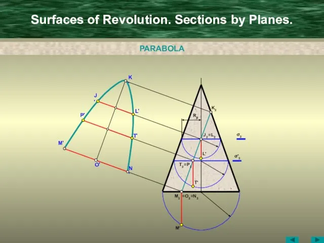
Слайд 20Surfaces of Revolution. Sections by Planes.
O'
M2
=N2
=O2
M'
M'
K2
J2
=L2
L'
J'
N'
K'
L'
Rjl
T2
=P2
T'
σ2
σ'2
T'
P'
PARABOLA
Surfaces of Revolution. Sections by Planes.
O'
M2
=N2
=O2
M'
M'
K2
J2
=L2
L'
J'
N'
K'
L'
Rjl
T2
=P2
T'
σ2
σ'2
T'
P'
PARABOLA
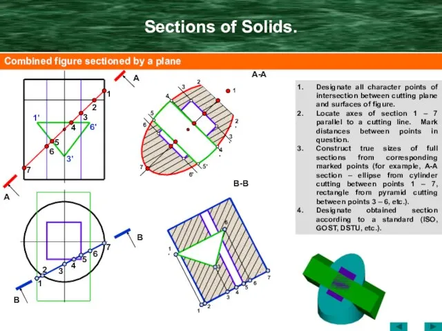
Слайд 21Sections of Solids.
Designate all character points of intersection between cutting plane and
Sections of Solids.
Designate all character points of intersection between cutting plane and
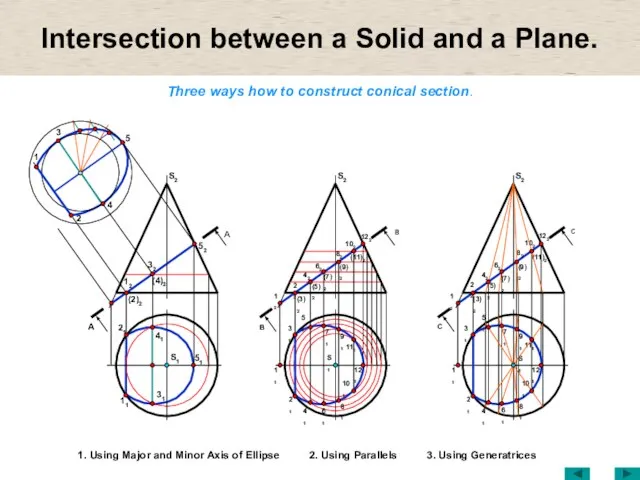
Слайд 22Intersection between a Solid and a Plane.
Three ways how to construct
Intersection between a Solid and a Plane.
Three ways how to construct
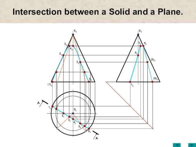
Слайд 23Intersection between a Solid and a Plane.
S1
(1)2
32
22
52
31
42
S2
21
51
62
11
61
41
13
33
23
(5)3
43
S3
(6)3
A
A
Intersection between a Solid and a Plane.
S1
(1)2
32
22
52
31
42
S2
21
51
62
11
61
41
13
33
23
(5)3
43
S3
(6)3
A
A
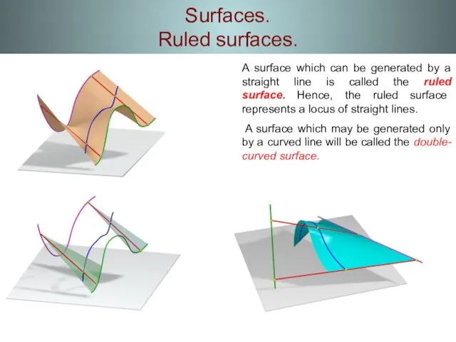
Слайд 24Surfaces.
Ruled surfaces.
A surface which can be generated by a straight line
Surfaces.
Ruled surfaces.
A surface which can be generated by a straight line
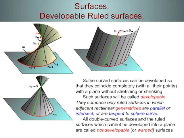
Слайд 25Surfaces.
Developable Ruled surfaces.
Some curved surfaces can be developed so that they
Surfaces.
Developable Ruled surfaces.
Some curved surfaces can be developed so that they
Слайд 26Surfaces.
Ruled surfaces with one Diretrix.
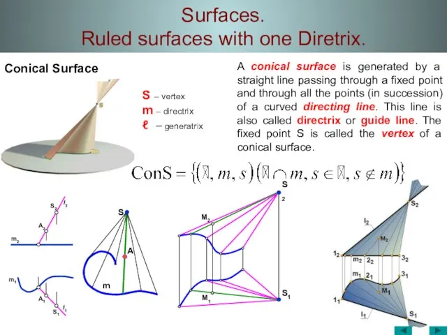
Conical Surface
m1
m2
A2
A
S
m
M2
M1
S2
l2
l1
A1
S1
A conical surface is generated
Surfaces.
Ruled surfaces with one Diretrix.
Conical Surface
m1
m2
A2
A
S
m
M2
M1
S2
l2
l1
A1
S1
A conical surface is generated
Слайд 27Surfaces.
Ruled surfaces with one Diretrix.
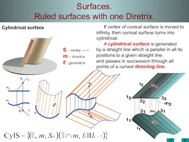
Cylindrical surface
A2
m2
m1
A1
m
l1
A
l
l2
A2
A1
If vertex of conical surface is
Surfaces.
Ruled surfaces with one Diretrix.
Cylindrical surface
A2
m2
m1
A1
m
l1
A
l
l2
A2
A1
If vertex of conical surface is
Слайд 28Surfaces.
Ruled surfaces with one Diretrix.
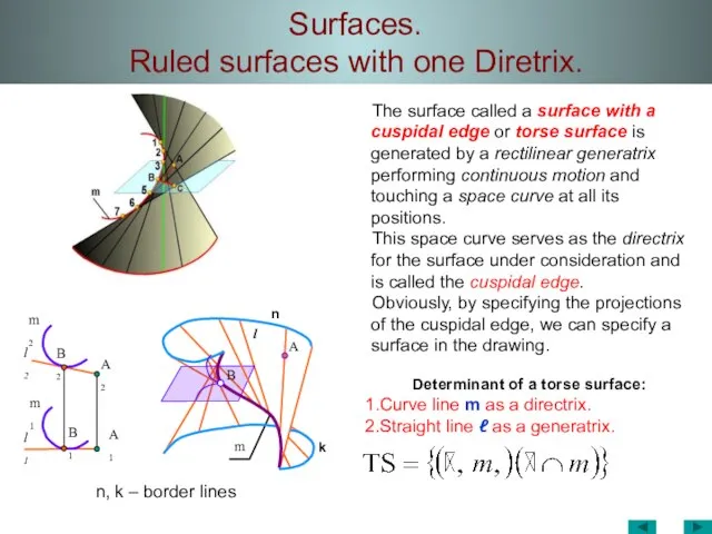
n, k – border lines
l1
m1
B1
m2
l2
B2
A1
A2
l
A
m
The surface called
Surfaces.
Ruled surfaces with one Diretrix.
n, k – border lines
l1
m1
B1
m2
l2
B2
A1
A2
l
A
m
The surface called
Слайд 29Surfaces.
Ruled surfaces with one Diretrix.
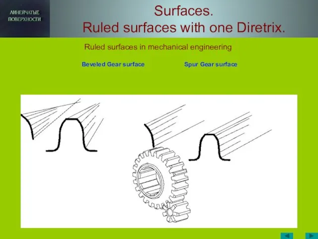
Beveled Gear surface Spur Gear surface
Surfaces.
Ruled surfaces with one Diretrix.
Beveled Gear surface Spur Gear surface
Слайд 30Surfaces.
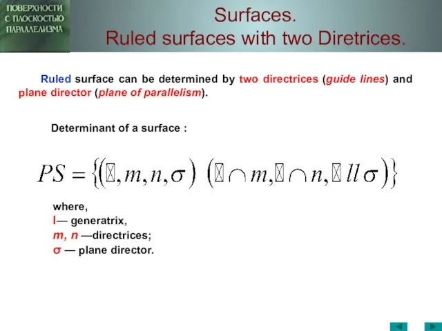
Ruled surfaces with two Diretrices.
where,
l— generatrix,
m, n —directrices;
σ
Surfaces.
Ruled surfaces with two Diretrices.
where,
l— generatrix,
m, n —directrices;
σ
Слайд 31Surfaces.
Ruled surfaces with two Diretrices.
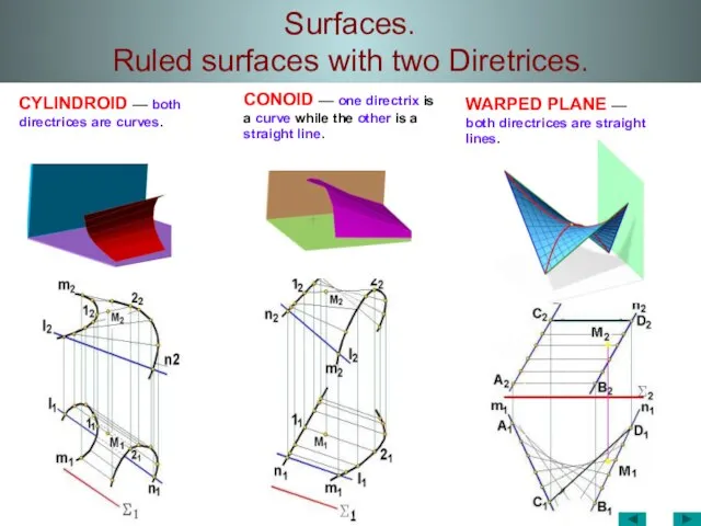
CYLINDROID –– both directrices are curves.
CONOID
Surfaces.
Ruled surfaces with two Diretrices.
CYLINDROID –– both directrices are curves.
CONOID
Слайд 32Surfaces.
Ruled surfaces with two Diretrices.
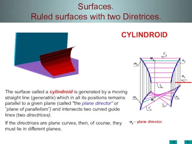
σ2 – plane director.
l1
l'1
m1
M1
l2
M2
m2
l'2
σ2
n2
n1
CYLINDROID
The surface called a
Surfaces.
Ruled surfaces with two Diretrices.
σ2 – plane director.
l1
l'1
m1
M1
l2
M2
m2
l'2
σ2
n2
n1
CYLINDROID
The surface called a
Слайд 33Surfaces.
Ruled surfaces with two Diretrices.
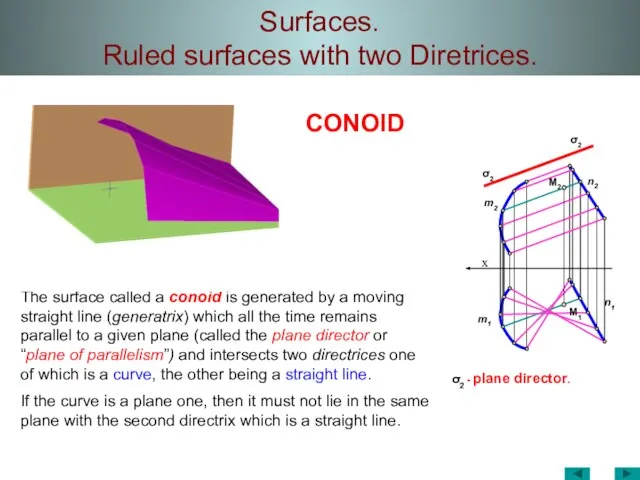
σ2 - plane director.
х
m2
n1
m1
σ2
σ2
n2
M2
M1
CONOID
The surface called a
Surfaces.
Ruled surfaces with two Diretrices.
σ2 - plane director.
х
m2
n1
m1
σ2
σ2
n2
M2
M1
CONOID
The surface called a
Слайд 34Surfaces.
Ruled surfaces with two Diretrices.
σ1 - plane director.
σ1
х
σ1
m2
M1
n2
n1
m1
M2
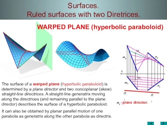
The surface of a
Surfaces.
Ruled surfaces with two Diretrices.
σ1 - plane director.
σ1
х
σ1
m2
M1
n2
n1
m1
M2
The surface of a
Слайд 35Surfaces.
Ruled surfaces with two Diretrices.
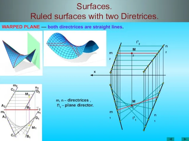
WARPED PLANE –– both directrices are straight
Surfaces.
Ruled surfaces with two Diretrices.
WARPED PLANE –– both directrices are straight
Слайд 36Surfaces.
Ruled surfaces with two Diretrices.
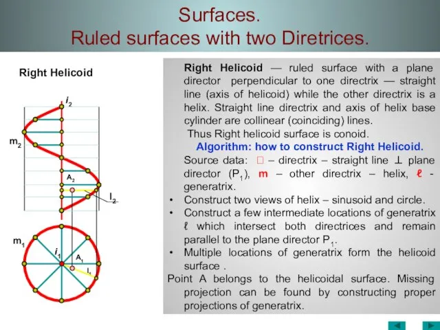
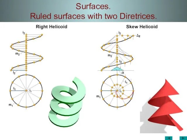
Right Helicoid
Right Helicoid — ruled surface
Surfaces.
Ruled surfaces with two Diretrices.
Right Helicoid
Right Helicoid — ruled surface
Слайд 37Surfaces.
Ruled surfaces with two Diretrices.
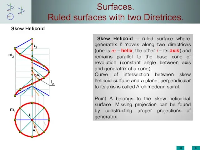
Skew Helicoid
Skew Helicoid –
Surfaces.
Ruled surfaces with two Diretrices.
Skew Helicoid
Skew Helicoid –
Слайд 38Surfaces.
Ruled surfaces with two Diretrices.
Right Helicoid
Skew Helicoid
Surfaces.
Ruled surfaces with two Diretrices.
Right Helicoid
Skew Helicoid
Слайд 39Surfaces.
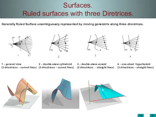
Ruled surfaces with three Diretrices.
1 – general view
(3 directrices –
Surfaces.
Ruled surfaces with three Diretrices.
1 – general view
(3 directrices –
Слайд 40Surfaces.
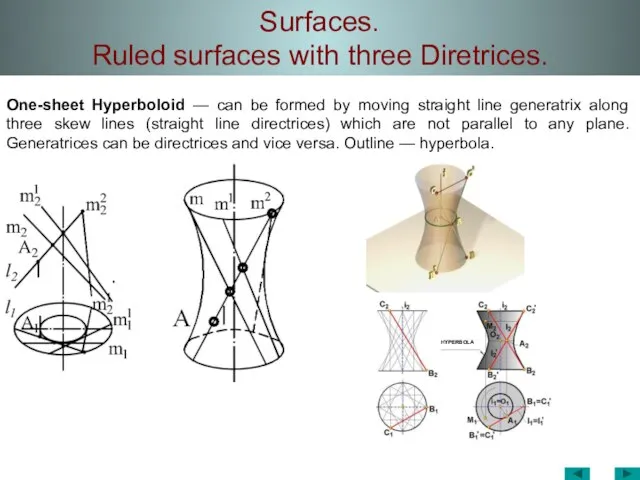
Ruled surfaces with three Diretrices.
One-sheet Hyperboloid — can be formed by
Surfaces.
Ruled surfaces with three Diretrices.
One-sheet Hyperboloid — can be formed by
Слайд 41Surfaces.
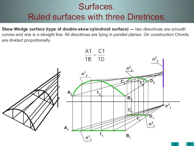
Ruled surfaces with three Diretrices.
Skew Wedge surface (type of double-skew cylindroid
Surfaces.
Ruled surfaces with three Diretrices.
Skew Wedge surface (type of double-skew cylindroid
Слайд 42Channel Surfaces.
Channel Surfaces.
Слайд 43Channel Surfaces.
On
Ln
L1
m
Channel Surfaces.
On
Ln
L1
m
Слайд 44Channel Surfaces.
A1
A
m1
O1
l
m2
l2
l1
O2
A2
O
m
Channel Surfaces.
A1
A
m1
O1
l
m2
l2
l1
O2
A2
O
m
Слайд 45Channel Surfaces.
Channel Surfaces.
Слайд 46Channel Surfaces.
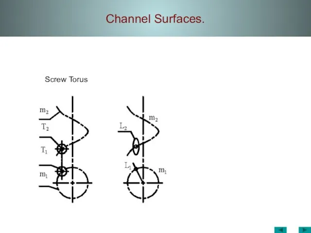
Screw Torus
Channel Surfaces.
Screw Torus
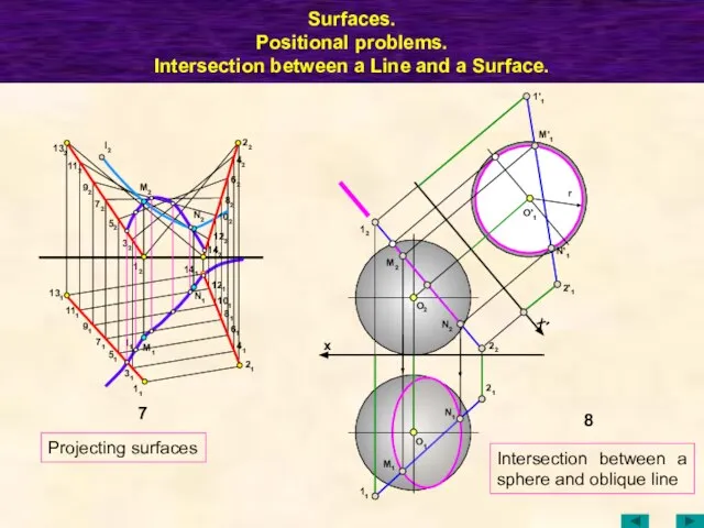
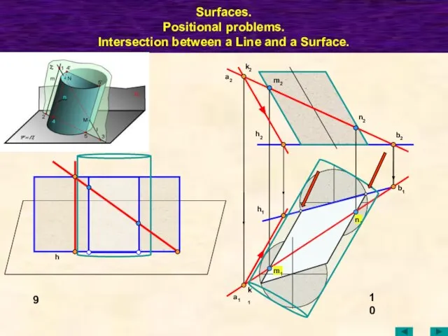
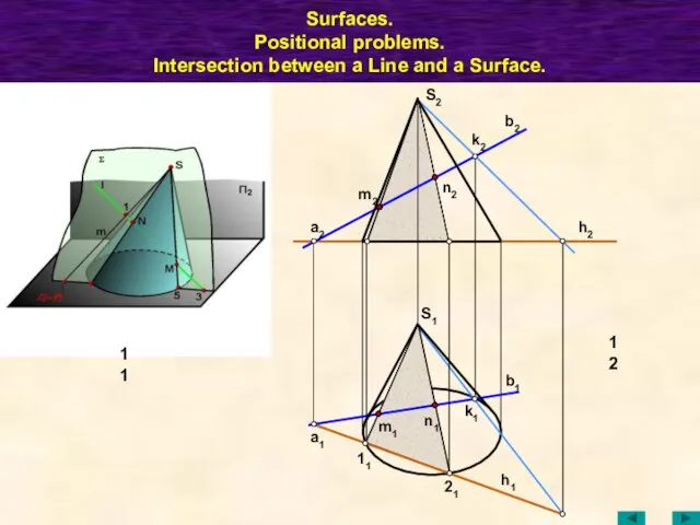
Слайд 47Surfaces.
Positional problems.
Intersection between a Line and a Surface.
1
11
21
2
12
22
T1
11=21
22
12
S1
S2
a1
=B1
K1
B2
T2
S1
K2
a2
S2
3
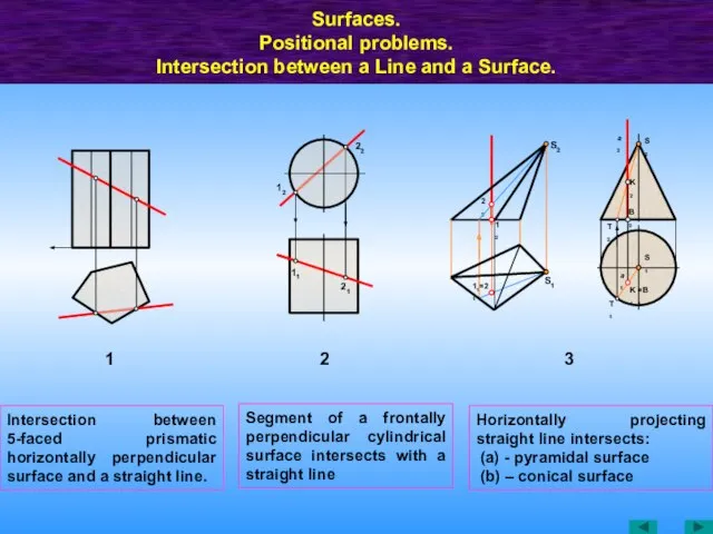
Intersection between
Surfaces.
Positional problems.
Intersection between a Line and a Surface.
1
11
21
2
12
22
T1
11=21
22
12
S1
S2
a1
=B1
K1
B2
T2
S1
K2
a2
S2
3
Intersection between
Слайд 48Surfaces.
Positional problems.
Intersection between a Line and a Surface.
M1
M2
A1
b2
A2
R1
K1
B1
T1
11
42
32
21
41
N1
31
N2
K2
12
22
T2
R2
B2
x
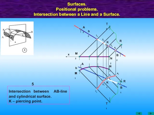
5
b1
Intersection between АВ-line
Surfaces.
Positional problems.
Intersection between a Line and a Surface.
M1
M2
A1
b2
A2
R1
K1
B1
T1
11
42
32
21
41
N1
31
N2
K2
12
22
T2
R2
B2
x
5
b1
Intersection between АВ-line
Слайд 49Intersection between АВ-line and surface of revolution.
Surfaces.
Positional problems.
Intersection between a
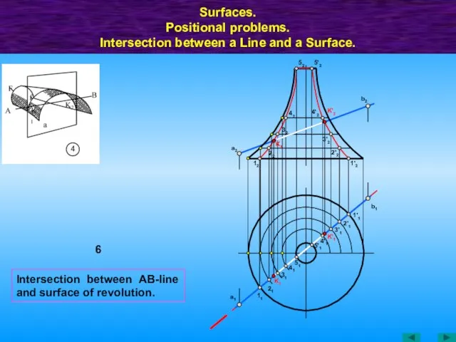
Intersection between АВ-line and surface of revolution.
Surfaces. Positional problems. Intersection between a
Слайд 50Surfaces.
Positional problems.
Intersection between a Line and a Surface.
8
12
N2
11
x
M1
N1
O1
M2
21
22
x'
2'1
M'1
1'1
r
O2
N'1
7
N1
141
132
112
91
l1
51
71
11
M1
M2
32
52
111
72
92
l2
12
61
21
41
81
101
122
121
142
82
62
42
22
131
31
N2
102
O'1
Projecting surfaces
Intersection between
Surfaces.
Positional problems.
Intersection between a Line and a Surface.
8
12
N2
11
x
M1
N1
O1
M2
21
22
x'
2'1
M'1
1'1
r
O2
N'1
7
N1
141
132
112
91
l1
51
71
11
M1
M2
32
52
111
72
92
l2
12
61
21
41
81
101
122
121
142
82
62
42
22
131
31
N2
102
O'1
Projecting surfaces
Intersection between
Слайд 51Surfaces.
Positional problems.
Intersection between a Line and a Surface.
10
a2
k2
a1
k1
h2
h1
b1
b2
m2
n2
m1
n1
h
9
Surfaces.
Positional problems.
Intersection between a Line and a Surface.
10
a2
k2
a1
k1
h2
h1
b1
b2
m2
n2
m1
n1
h
9
Слайд 52Surfaces.
Positional problems.
Intersection between a Line and a Surface.
n1
12
m1
11
a1
21
k1
b1
h1
S1
h2
b2
k2
a2
n2
m2
S2
11
Surfaces.
Positional problems.
Intersection between a Line and a Surface.
n1
12
m1
11
a1
21
k1
b1
h1
S1
h2
b2
k2
a2
n2
m2
S2
11
Слайд 53Surfaces.
Positional problems.
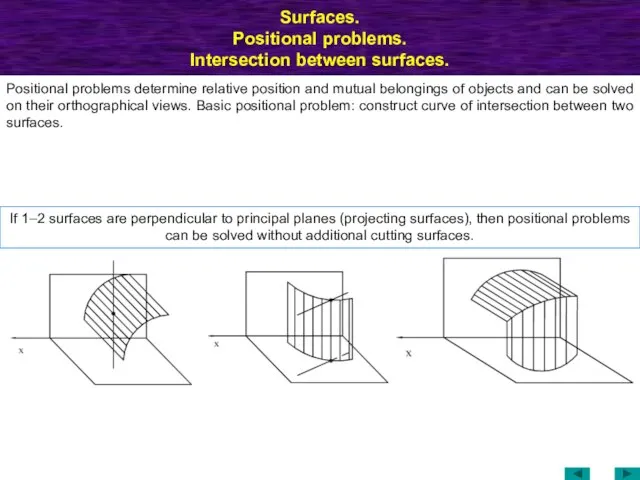
Intersection between surfaces.
Positional problems determine relative position and
Surfaces.
Positional problems.
Intersection between surfaces.
Positional problems determine relative position and
Слайд 54Intersection between Surfaces
A2
A1
B2
C2
C1
B1
A3
=C3
B3
S2
S3
S1
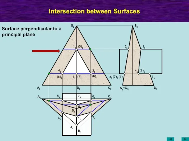
12
32
(5)2
(7)2
(8)2
13
33
53
83
(7)3
(6)3
43
(2)3
41
11
31
21
61
81
51
71
22
42
(6)2
Surface perpendicular to a principal plane
Intersection between Surfaces
A2
A1
B2
C2
C1
B1
A3
=C3
B3
S2
S3
S1
12
32
(5)2
(7)2
(8)2
13
33
53
83
(7)3
(6)3
43
(2)3
41
11
31
21
61
81
51
71
22
42
(6)2
Surface perpendicular to a principal plane
Слайд 55Intersection between Surfaces.
Y34
12
(2')2
(3')2
42
(5')2
(4')2
32
22
(1')2
52
11
41
(2)1
(3)1
(3')1
4'1
51
(2')1
5'1
1'1
Y1'
Y6
62
61
6'1
(6')2
Y6
Y1'
Y34
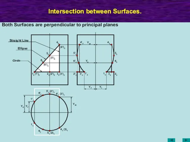
Both Surfaces are perpendicular to principal planes
Y1
13
33
23
43
53
63
1'3
3'3
2'3
6'3
5'3
4'3
Circle
Ellipse
Straight Line
Intersection between Surfaces.
Y34
12
(2')2
(3')2
42
(5')2
(4')2
32
22
(1')2
52
11
41
(2)1
(3)1
(3')1
4'1
51
(2')1
5'1
1'1
Y1'
Y6
62
61
6'1
(6')2
Y6
Y1'
Y34
Both Surfaces are perpendicular to principal planes
Y1
13
33
23
43
53
63
1'3
3'3
2'3
6'3
5'3
4'3
Circle
Ellipse
Straight Line
Слайд 56МТК
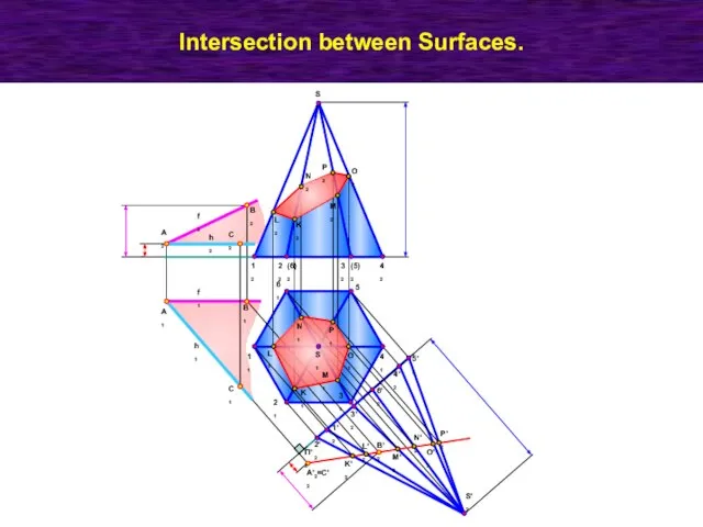
Intersection between Surfaces.
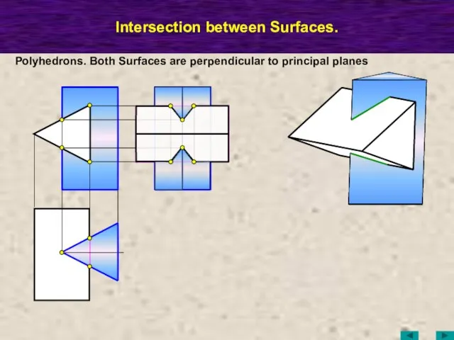
Polyhedrons. Both Surfaces are perpendicular to principal planes
МТК
Intersection between Surfaces.
Polyhedrons. Both Surfaces are perpendicular to principal planes
Слайд 57МТК
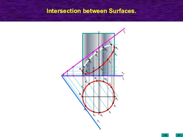
Intersection between Surfaces.
f2
h1
62
B1
22
32
42
52
72
f1
h2
11
A1
21
31
41
51
71
81
91
101
61
12
82
102
A2
B2
92
МТК
Intersection between Surfaces.
f2
h1
62
B1
22
32
42
52
72
f1
h2
11
A1
21
31
41
51
71
81
91
101
61
12
82
102
A2
B2
92
Слайд 58Intersection between Surfaces.
B2
A2
C2
C1
B1
A1
11
21
31
41
51
61
S1
42
32
(6)2
12
(5)2
22
S2
S'2
П'2
6'2
4'2
5'2
3'2
1'2
2'2
K'2
L'2
M'2
N'2
O'2
P'2
B'2
A'2=C'2
K1
L1
N1
M1
P1
O1
L2
N2
P2
O2
M2
K2
h2
h1
f2
f1
Intersection between Surfaces.
B2
A2
C2
C1
B1
A1
11
21
31
41
51
61
S1
42
32
(6)2
12
(5)2
22
S2
S'2
П'2
6'2
4'2
5'2
3'2
1'2
2'2
K'2
L'2
M'2
N'2
O'2
P'2
B'2
A'2=C'2
K1
L1
N1
M1
P1
O1
L2
N2
P2
O2
M2
K2
h2
h1
f2
f1
Слайд 59Intersection between Surfaces. Cutting Surface Method.
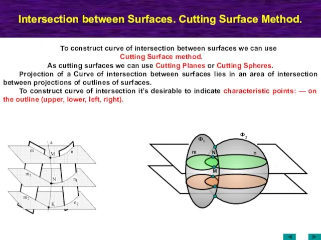
To construct curve of intersection between surfaces
Intersection between Surfaces. Cutting Surface Method.
To construct curve of intersection between surfaces
Слайд 60Intersection between Surfaces.
Cutting Plane Method.
S2
(2')2
(3')2
42
(5')2
(4')2
32
22
52
(4')3
(4)3
63
6'3
(3)3
23
2'3
1'3
11
1'1
21
31
3'1
2'1
41
4'1
61
6'1
S3
S1
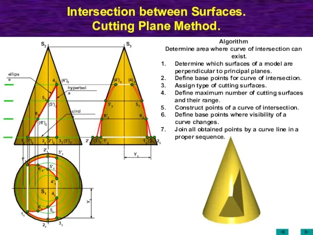
Algorithm
Determine area where curve of intersection can
Intersection between Surfaces.
Cutting Plane Method.
S2
(2')2
(3')2
42
(5')2
(4')2
32
22
52
(4')3
(4)3
63
6'3
(3)3
23
2'3
1'3
11
1'1
21
31
3'1
2'1
41
4'1
61
6'1
S3
S1
Algorithm
Determine area where curve of intersection can
Слайд 61Intersection between Surfaces.
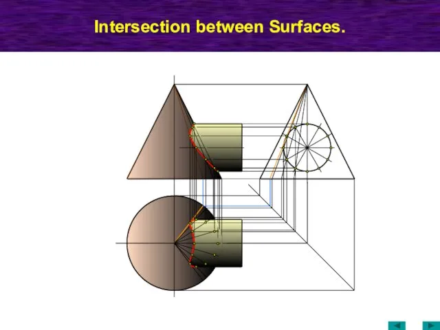
Intersection between Surfaces.
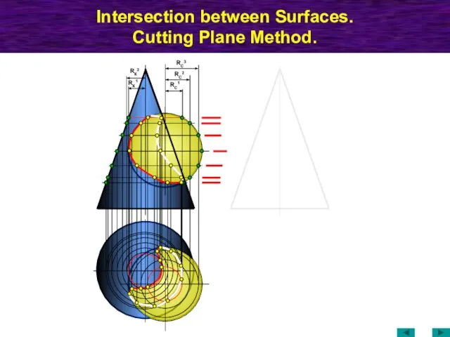
Слайд 62Intersection between Surfaces.
Cutting Plane Method.
RC1
RC2
RК1
RК2
RC3
Intersection between Surfaces.
Cutting Plane Method.
RC1
RC2
RК1
RК2
RC3
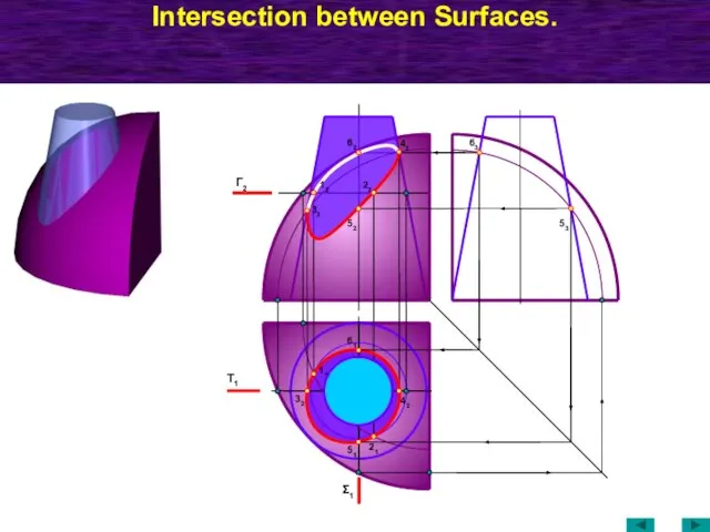
Слайд 63Intersection between Surfaces.
Τ1
Γ2
21
11
42
32
Σ1
51
61
52
53
63
42
62
12
22
32
Intersection between Surfaces.
Τ1
Γ2
21
11
42
32
Σ1
51
61
52
53
63
42
62
12
22
32
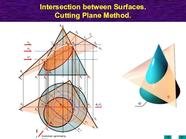
Слайд 64Intersection between Surfaces.
Cutting Plane Method.
а1
61
81
41
42
92
31
Σ1
Δ1=f1
72
52
22
b2
h2
12
f2
51
61
A1
71
h'2
h''2
а2
B1
D1
S1
21
h'1
h'2
b1
32
81
A2
B2
C2
11
Common symmetry plane
S2
91
C1
D2
Intersection between Surfaces.
Cutting Plane Method.
а1
61
81
41
42
92
31
Σ1
Δ1=f1
72
52
22
b2
h2
12
f2
51
61
A1
71
h'2
h''2
а2
B1
D1
S1
21
h'1
h'2
b1
32
81
A2
B2
C2
11
Common symmetry plane
S2
91
C1
D2
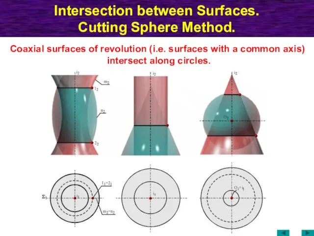
Слайд 65Intersection between Surfaces.
Cutting Sphere Method.
Coaxial surfaces of revolution (i.e. surfaces with
Intersection between Surfaces.
Cutting Sphere Method.
Coaxial surfaces of revolution (i.e. surfaces with
Слайд 66Intersection between Surfaces.
Cutting Sphere Method.
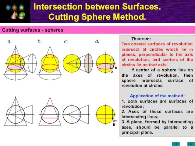
Cutting surfaces - spheres
Theorem:
Two coaxial
Intersection between Surfaces.
Cutting Sphere Method.
Cutting surfaces - spheres
Theorem:
Two coaxial
Слайд 67Intersection between Surfaces.
Cutting Sphere Method.
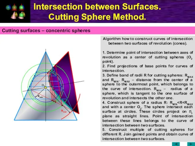
Algorithm how to construct curves of intersection
Intersection between Surfaces.
Cutting Sphere Method.
Algorithm how to construct curves of intersection
Слайд 68Intersection between Surfaces.
Cutting Sphere Method.
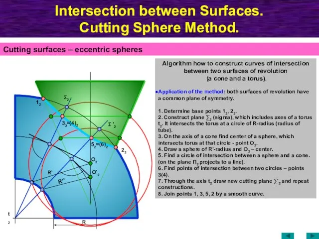
Cutting surfaces – eccentric spheres
Algorithm how to
Intersection between Surfaces.
Cutting Sphere Method.
Cutting surfaces – eccentric spheres
Algorithm how to
Слайд 69Intersection between Surfaces.
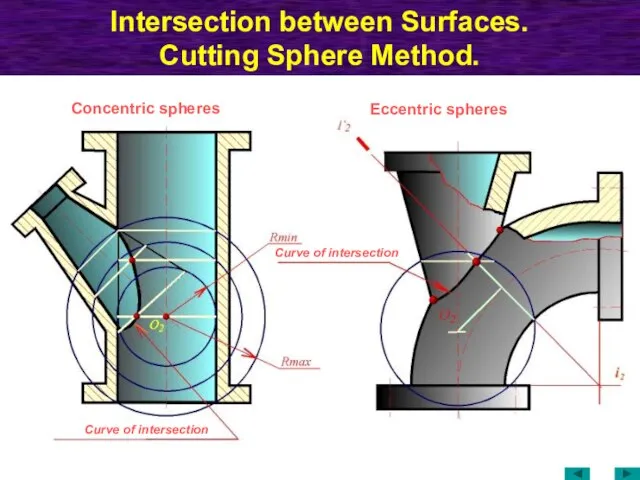
Cutting Sphere Method.
Curve of intersection
Curve of intersection
Concentric spheres
Eccentric spheres
Intersection between Surfaces.
Cutting Sphere Method.
Curve of intersection
Curve of intersection
Concentric spheres
Eccentric spheres
Слайд 70Intersection between Surfaces.
Particular case.
In general two second-order surfaces of revolution intersect
Intersection between Surfaces.
Particular case.
In general two second-order surfaces of revolution intersect
Слайд 71Intersection between Surfaces.
Cutting sphere method. Particular case.
Two second-order surfaces circumscribed about
Intersection between Surfaces.
Cutting sphere method. Particular case.
Two second-order surfaces circumscribed about
Слайд 72Intersection between Surfaces.
Cutting sphere method. Particular case.
Two second-order surfaces circumscribed about
Intersection between Surfaces.
Cutting sphere method. Particular case.
Two second-order surfaces circumscribed about
Слайд 73Intersection between Surfaces.
Cutting sphere method. Particular case.
Curve of intersection
Curve of intersection
Intersection between Surfaces.
Cutting sphere method. Particular case.
Curve of intersection
Curve of intersection
Слайд 74Developments.
Properties of developments.
Each point on the development corresponds to a single point
Developments.
Properties of developments.
Each point on the development corresponds to a single point
Слайд 75Methods of exact development.
1. Triangulation method.
2. Radial-line method.
3. Stretch-out-line (right
Methods of exact development.
1. Triangulation method.
2. Radial-line method.
3. Stretch-out-line (right
Слайд 76Developments.
Triangulation method.
Development of a pyramid. Lateral faces of a pyramid are
Developments.
Triangulation method.
Development of a pyramid. Lateral faces of a pyramid are
Слайд 77Developments.
Radial Line method.
C0
A1
A2
C0
A0
B0
D0
D1
C1
F1
B1
C2
B2
E1
F0
F2
D2
E2
E0
D0
This method is used when a base of a
Developments.
Radial Line method.
C0
A1
A2
C0
A0
B0
D0
D1
C1
F1
B1
C2
B2
E1
F0
F2
D2
E2
E0
D0
This method is used when a base of a
Слайд 78Developments.
Stretch out Line method.
This method is used when generatrices are parallel
Developments.
Stretch out Line method.
This method is used when generatrices are parallel
Слайд 79Development of a conical surface. Triangulation method.
Substitute (approximate) the conical surface
Development of a conical surface. Triangulation method.
Substitute (approximate) the conical surface
Слайд 80Conventional developments.
Development of Toroidal surface— Zone Method
Each parallel of a surface is
Conventional developments.
Development of Toroidal surface— Zone Method
Each parallel of a surface is
 ОАО Туймазинский мясокомбинат
 Новая форма ГИА
 Права и обязанности в Конституции России
 Изделия в технике канзаши и в технике холодного фарфора
 это надо скинуть шкарину
 Презентация на тему Изобразительное искусство в семье пластических искусств
  Методы контроля при занятии физической культурой
 Основы религиозных культур и светской этики.
 Фотоаппарат. СРС
 Проектирование электронного контента: основные принципы электронные курсы банк тестов
 ФОРЕКС - производный финансовый инструмент, в основе которого лежит обязательство компании-маркетмейкера выплатить клиенту разни
 The role of the service industry in the modern Economy
  Интернет-проект «Забытый памятник незабытой войны»
 Генерация идей для создания успешных проектов
 Сетевые технологии: терминология, устройства
 Полисахариды
 Обрушение смыслов: как вернуть себе желание жить после большой потери?
 Модели реализации межшкольными учебными комбинатами профориентационной работы со школьниками в рамках сетевого взаимодействия
 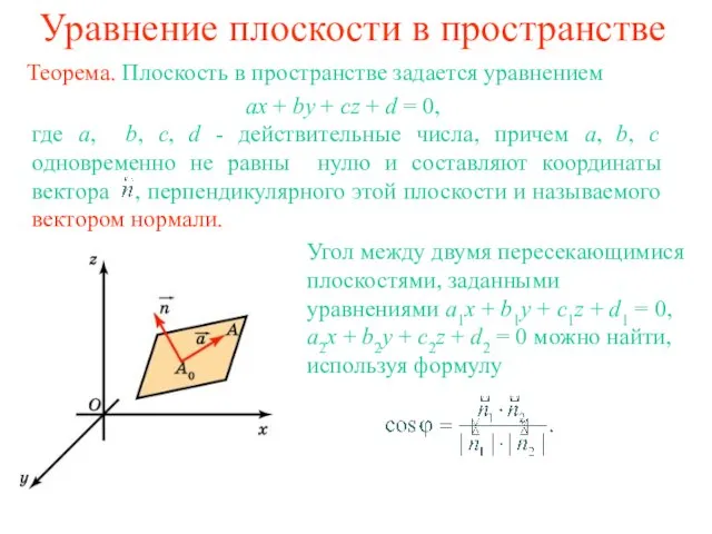 Уравнение плоскости в пространстве
 Политика. Повторение. 9 класс
 Технология контроля поверхностного слоя песчано-глинистой литейной формы
 В мире «кривых». Работа Яковлевой Яны 10b 2009 г.
 Оптические приборы. Глаз
 Математические модели и оптимальные процессы в макросистемах (термодинамика и экономика)
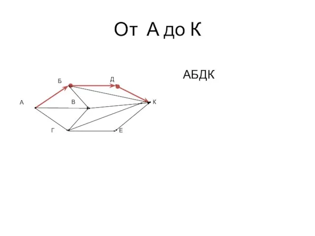 От А до К
 7. Презентация 2 этап (пример)
 Этюд простой архитектурной постройки сельского типа
 Расследование преступлений, совершенных организованными преступными группами