Слайд 2Introduction
Dynamic positioning (DP) is a rapidly maturing technology, having been born of
necessity as a result of the increasing demands of the rapidly expanding oil and gas exploration industry in the 1960s and early 1970s. Even now, when there exist over 1,000 DP-capable vessels, the majority of them are operationally related to the exploration or exploitation of oil and gas reserves.
The first vessel to fulfil the accepted definition of DP was the "Eureka", of 1961, designed and engineered by Howard Shatto. This vessel was fitted with an analogue control system of very basic type, interfaced with a taut wire reference. Equipped with steerable thrusters fore and aft in addition to her main propulsion, this vessel was of about 450 tons displacement and length 130 feet.
Слайд 3By the late 1970s, DP had become a well established technique. In
1980 the number of DP capable vessels totalled about 65, while by 1985 the number had increased to about 150. Currently (2008) it stands at over 1,000 and is still expanding. It is interesting to note the diversity of vessel types and functions using DP, and the way that, during the past twenty years, this has encompassed many functions unrelated to the offshore oil and gas industries. A list of activities executed by DP vessels would include the following:
• coring
• exploration drilling (core sampling)
• production drilling
• diver support
• pipelay (rigid and flexible pipe)
• cable lay and repair
• multi-role
• accommodation or "flotel" services
• hydrographic survey
• pre- or post-operational survey
• wreck survey, salvage and removal
Слайд 4• lifting (topsides and subsea)
• dredging
• rockdumping (pipeline protection)
• subsea installation
• well
stimulation and workover
• platform supply
• shuttle tanker offtake
• Floating production (with or without storage)
• heavy lift cargo transport
• passenger cruises
• mine countermeasures
• oceanographical research
• seabed mining
DP is also used in
• rocket launch platform positioning
• repair/maintenance support to military vessels
• ship-to-ship transfer and
• manoeuvring conventional vessels
Слайд 5DP Advantages:
• Vessel is fully self-propelled; no tugs are required at any
stage of the operation
• Setting-up on location is quick and easy
• Vessel is very manoeuvrable
• Rapid response to weather changes is possible (weather vane)
• Rapid response to changes in the requirements of the operation
• Versatility within system (i.e. track-follow, ROV-follow and other specialist functions)
• Ability to work in any water depth
• Can complete short tasks more quickly, thus more economically
• Avoidance of risk of damaging seabed hardware from mooring lines and anchors
• Avoidance of cross-mooring with other vessels or fixed platforms
• Can move to new location rapidly (also avoid bad weather)
Слайд 6DP Disadvantages:
• High capex and opex
• Can fail to keep position due
to equipment failure
• Higher day rates than comparable moored systems
• Higher fuel consumption
• Thrusters are hazards for divers and ROVs
• Can lose position in extreme weather or in shallow waters and strong tides
• Position control is active and relies on human operator (as well as equipment)
• Requires more personnel to operate and maintain equipment
Слайд 7Basic Principles of DP
Dynamic Positioning can be described as an integration of
a number of shipboard systems to obtain the ability of accurate manoeuvrability. DP can be defined as:
A system which automatically controls a vessel’s position and heading exclusively by means of active thrust.
The above definition includes remaining at a fixed location, but also precision manoeuvring, tracking and other specialist positioning abilities.
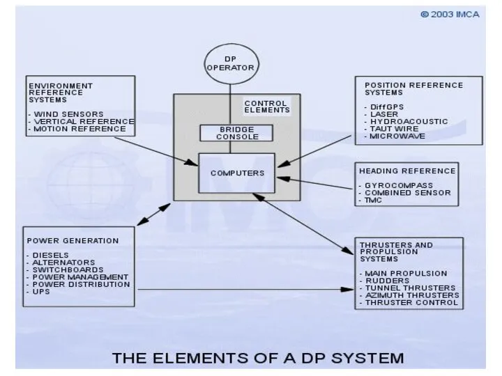
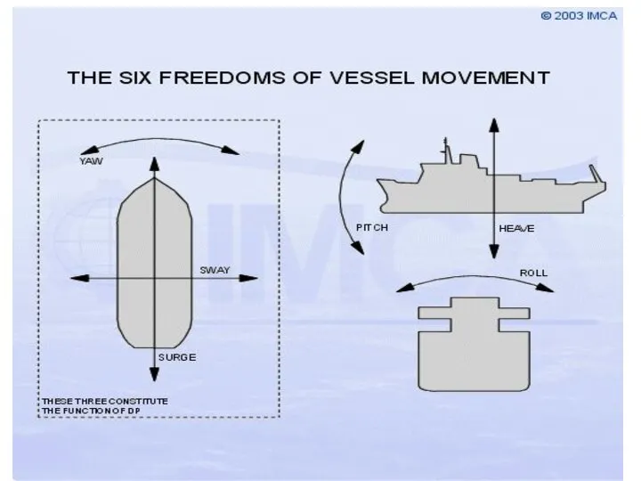
A convenient way of visualising the inter-relation of the various elements of a DP system is to divide the system into six parts, as the following sketch shows.
Слайд 9
The prime function of a DP system is to allow a vessel
to maintain position and heading. A variety of further sub-functions may be available, such as track-follow, or weathervane modes, but the control of position and heading is fundamental.
Any vessel (or other object) has six freedoms of movement; three rotations and three translations. In a vessel they can be illustrated as roll, pitch, yaw, surge, sway and heave.
Слайд 11
Dynamic positioning is concerned with the automatic control of surge, sway and
yaw. Surge and sway, of course, comprise the position of the vessel, while yaw is defined by the vessel heading. Both of these are controlled about desired or "setpoint" values input by the operator, i.e. position setpoint, and heading setpoint. Position and heading must be measured in order to obtain the error from the required value. Position is measured by one or more of a range of position references, while heading information is provided from one or more gyrocompasses. The difference between the setpoint and the feedback is the error or offset, and the DP system operates to minimise these errors.
Слайд 12Forces
The forces acting on the vessel are the environmental forces, including wind,
current and waves, and task dependent forces such as cable, pipe, anchors, tow ropes. It is important to realise that environment forces are very variable.
Environmental forces:
Wind
Wind speed and direction are constantly changing. The wind forces can be defined by three components, surge, sway and yaw. To be meaningful, the point of application of the forces must be defined. The wind speed varies as a function of height above sea level, but above 3-5 metres to the height of the vessel, the change is small. The forces acting on the vessel are very dependent on the superstructure shape (the part of the vessel above the water line), and the wind direction relative to the vessel. Wind is normally defined in knots or metres/sec, and in direction with respect to north or the vessel. In normal usage, a north wind moves the vessel from north to south.
Слайд 13
Sea Current
The sea current can be caused by the slope of the
seabed, tidal or storm surges along coastline, outflows from rivers. It can also be wind driven. It can be caused by the effect of heating and cooling and salinity (thermohaline). The effect is only a few knots, and usually slow variation over hours and days. The effect of current on the vessel is a characteristic of vessel shape. In normal usage, a northerly current moves the vessel from south to north.
Waves
Waves are also described as sea state. A fully developed sea is the maximum wave size generated by a given wind. It takes many hours to build up and die down. The significant wave height is the mean of the 1/3 highest waves. The spectral density of the waves increases and moves to lower frequencies as wave height increases. The spectrum of wave energy is defined by Jonswap for the North Sea, and Pierson-Moskowitz for the North Atlantic. The direction of propagation of the waves also matters, but predicting wave drift forces is complex.
Слайд 14CONTROL SYSTEM
DP is a multiloop feedback control system. The primary function of
the control system is designed to keep the vessel at a specified position, or on a specified track, and with a set heading, each within tolerable limits. The system must be able to handle transient conditions such as changes in external forces, failure of a signal from sensors and position measurement equipment, and system hardware failures.
Secondary functions are to control the vessel so as to minimise fuel consumption and to keep the thruster wear to a minimum. It is possible to divide DP control into two separate functions:
• Measure the deviation of the vessel from its target position and estimate/calculate the forces needed to restore the vessel to the required position
• Measure the environmental forces acting on the vessel and estimate/calculate the forces needed to counteract their effect
Слайд 16The control system consists of the following components:
• Model Ship
This is as
accurate a description as possible of the vessel’s response to any external forces. The model should be subjected to the same forces that effect the real vessel: thrusters, wind, and waves, currents, anchors, other external forces such as cable/pipe tensions.
• State Gains
These are the factors that determine the tonnes thrust from the speed and position errors.
• Thruster Allocation
This is a set of equations which take the total thrust demand, expressed in X, Y, N coordinates, to be applied by the vessel's thrusters and converts it into individual thrusts matched to the available thrusters and their characteristics.
• Actual Thrusters
These are the available working thrusters.
• Thruster Model
This model takes the individual thruster demands and calculates the total thrust exerted on the vessel.
Слайд 17
• Pool
This combines the various estimates of the vessel position, and creates
a best estimate of position.
• Kalman Gains
The factors, which can vary between 0 and 1, determine if the model or
estimated position is to be given preference. A value of 0.5 would provide equal weight.
Wind Speed and Direction
The wind speed and direction are converted into the estimated wind forces on the vessel.
Слайд 18Position Reference Systems
The number of position references enabled depends on a number
of factors. In particular, the level of risk involved in the operation, the redundancy level that is sensible for the operation, the availability of references of a suitable type, and the consequences of loss of one or more position references.
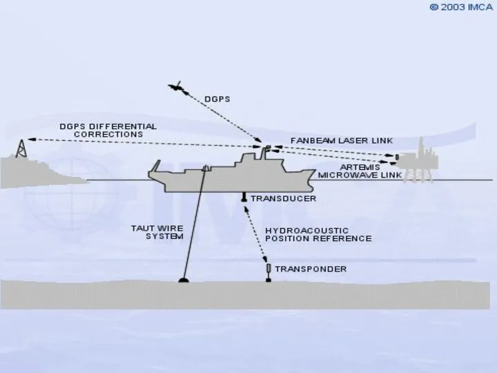
A variety of position reference systems is used by DP systems. The most common are: differential global positioning (DGPS), taut wires, hydroacoustics (HPR), and line-of-sight laser or microwave systems.
Слайд 20
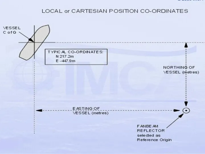
Position information from position-reference systems may be received by the DP system
in many forms. In addition, the type of co-ordinate system used may be cartesian or geodetic. The DP control system is able to handle information based on either co-ordinate system. A Cartesian, or local, co-ordinate system is based upon a flat-surface two-dimensional measurement of the North/South (X) and East/West (Y) distances from a locally defined reference origin. This reference origin will be taken from one of the position reference systems (e.g. HPR transponder, fanbeam reflector, taut wire depressor weight location). This type of co-ordinate reference system is purely local, or relative, not absolute or earth-fixed.
Слайд 22
Hydroacoustic Position Reference (HPR)
Underwater acoustics have many applications, one of which is
the provision of position reference for DP purposes.
Acoustic positioning is also used for tracking of underwater vehicles or equipment, the marking of underwater features or hardware and the control of subsea equipment by means of acoustic telemetry.
There are three types of acoustic position reference systems in common use - ultra- or super-short baseline systems (USBL or SSBL), short baseline systems (SBL) and long baseline systems (LBL). Each has advantages and disadvantages which determine when and how each is used.
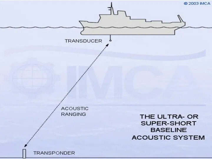
Слайд 23Ultra- or Super-Short Baseline Acoustic System
The principle of position measurement involves communication
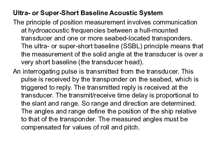
at hydroacoustic frequencies between a hull-mounted transducer and one or more seabed-located transponders. The ultra- or super-short baseline (SSBL) principle means that the measurement of the solid angle at the transducer is over a very short baseline (the transducer head).
An interrogating pulse is transmitted from the transducer. This pulse is received by the transponder on the seabed, which is triggered to reply. The transmitted reply is received at the transducer. The transmit/receive time delay is proportional to the slant and range. So range and direction are determined. The angles and range define the position of the ship relative to that of the transponder. The measured angles must be compensated for values of roll and pitch.
Слайд 25Long Baseline System
In deepwater locations, where the accuracy of the other types
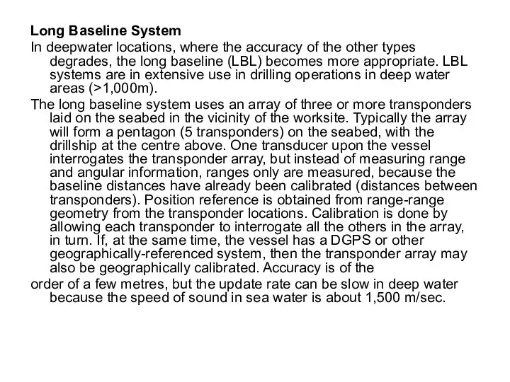
degrades, the long baseline (LBL) becomes more appropriate. LBL systems are in extensive use in drilling operations in deep water areas (>1,000m).
The long baseline system uses an array of three or more transponders laid on the seabed in the vicinity of the worksite. Typically the array will form a pentagon (5 transponders) on the seabed, with the drillship at the centre above. One transducer upon the vessel interrogates the transponder array, but instead of measuring range and angular information, ranges only are measured, because the baseline distances have already been calibrated (distances between transponders). Position reference is obtained from range-range geometry from the transponder locations. Calibration is done by allowing each transponder to interrogate all the others in the array, in turn. If, at the same time, the vessel has a DGPS or other geographically-referenced system, then the transponder array may also be geographically calibrated. Accuracy is of the
order of a few metres, but the update rate can be slow in deep water because the speed of sound in sea water is about 1,500 m/sec.
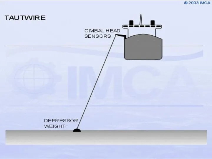
Слайд 26Taut Wire Position Reference
A taut wire is a useful position reference, particularly
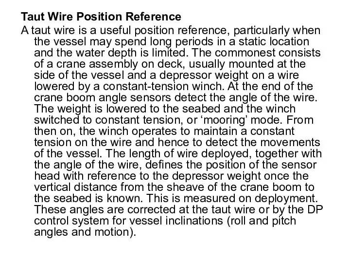
when the vessel may spend long periods in a static location and the water depth is limited. The commonest consists of a crane assembly on deck, usually mounted at the side of the vessel and a depressor weight on a wire lowered by a constant-tension winch. At the end of the crane boom angle sensors detect the angle of the wire. The weight is lowered to the seabed and the winch switched to constant tension, or ‘mooring’ mode. From then on, the winch operates to maintain a constant tension on the wire and hence to detect the movements of the vessel. The length of wire deployed, together with the angle of the wire, defines the position of the sensor head with reference to the depressor weight once the vertical distance from the sheave of the crane boom to the seabed is known. This is measured on deployment. These angles are corrected at the taut wire or by the DP control system for vessel inclinations (roll and pitch angles and motion).
Слайд 28The DGPS Position Reference System
DGPS has become the most commonly-used position reference
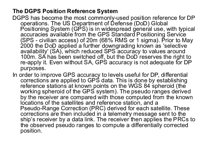
for DP operations. The US Department of Defense (DoD) Global Positioning System (GPS) is in widespread general use, with typical accuracies available from the GPS Standard Positioning Service (SPS - civilian access) of 20m (68% RMS or 1 sigma). Prior to May 2000 the DoD applied a further downgrading known as ‘selective availability’ (SA), which reduced SPS accuracy to values around 100m. SA has been switched off, but the DoD reserves the right to re-apply it. Even without SA, GPS accuracy is not adequate for DP purposes.
In order to improve GPS accuracy to levels useful for DP, differential corrections are applied to GPS data. This is done by establishing reference stations at known points on the WGS 84 spheroid (the working spheroid of the GPS system). The pseudo ranges derived by the receiver are compared with those computed from the known locations of the satellites and reference station, and a Pseudo-Range Correction (PRC) derived for each satellite. These corrections are then included in a telemetry message sent to the ship’s receiver by a data link. The receiver then applies the PRCs to the observed pseudo ranges to compute a differentially corrected position.
Слайд 29Network DGPS
Most DGPS services accept multiple differential inputs obtained from an array
of reference stations widely separated. Generally, network DGPS systems provide greater stability and accuracy, and remove more of the ionospheric error than obtainable from a single reference station. Network systems are more comprehensively monitored at the Hub, or control stations, where user information or warning data may be generated and sent out.
The choice of which link to hire or purchase must be made based on the vessel's expected work areas. If a vessel is expected to be working near fixed platforms, a local HF connection can be best. For floating production, storage and offloading (FPSO) vessels, a local UHF link and relative GPS solution can be the best arrangement.
The accuracy obtainable from DGPS systems is in the area of 1-3m dependent upon the distances to the reference stations, ionospheric conditions, and the constellation of satellites available. DGPS tends to be less reliable in close proximity to large structures (ie. platforms) due to interference to satellite and differential signals. DGPS performance near the magnetic equator has suffered due to scintillation (sun spot activity causing ionospheric disturbances). This reached a peak in 2001 with the maximum of the 11-year sunspot cycle.
Слайд 30
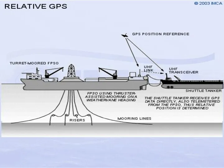
Relative GPS
Some DP operations require the positioning of a vessel relative to
a moving structure. An example of this is the operation of a DP shuttle tanker loading via a bow loading hose from the stern of an FPSO. The FPSO may be turret-moored, so it can weathervane. The stern of the FPSO describes the arc of a circle, as well as surge sway and yaw motions, providing a complex positioning problem for the shuttle tanker.
An Artemis20 and a DARPS system (Differential, Absolute and Relative Positioning System) are configured to handle this problem. For the measurement of relative position by GPS, differential corrections are not needed, as the errors induced are the same for the shuttle tanker as they are for the FPSO. A DARPS transmitter on the FPSO sends the received GPS data to the UHF receiver aboard the shuttle tanker. A computer aboard the shuttle tanker then calculates a range/bearing from the FPSO’s stern, which is put in to the DP control system as position reference in the same way as Artemis.
Слайд 32
The GLONASS system
GLONASS (the Global Navigation Satellite System11) is the Russian counterpart
to the American GPS, being similar in design and operation. The system was initiated with the first satellite launches in 1982, and by 1996, 24 operational satellites were in orbit. However, this number has not been maintained and the number available has, at times, been inadequate for good positioning.
The principles and practice of position determination with GLONASS are identical to that of GPS, using pseudo-range measurement from time and ephemeris data transmitted from the satellites.
The higher orbital inclination of GLONASS satellites (65°), compared to the GPS constellation (55°), results in better satellite availability in higher latitudes. The limited satellite availability precludes the use of GLONASS as a continuous position reference for DP. A number of combined GPS/GLONASS receivers are available. These have the effect of increasing the number of usable satellites within view of the observer.
Слайд 33
Laser-Based Position Reference
Two laser DP position references are in use -Fanbeam and
CyScan21.
Both systems lock onto a single target and/or a number of targets on the structure, from which position must be maintained. Light pulses are sent and received so that range and bearing can be measured.
Ranges vary according to weather conditions, when the systems will be affected by reduced optical visibility.
Слайд 34Sensors
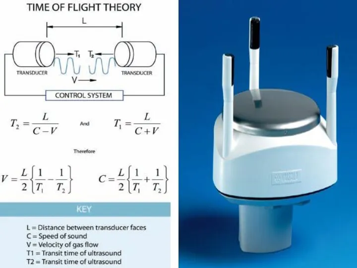
Wind ultrasonic sensors
Ultrasonic anemometers have the advantage of having no moving parts
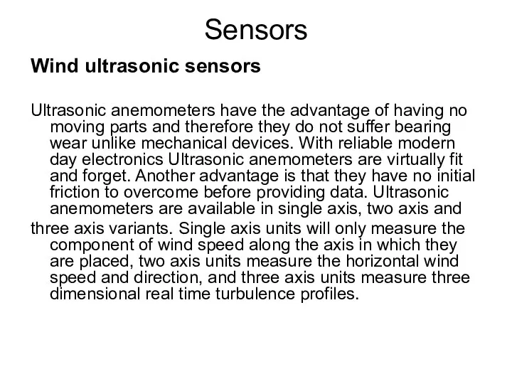
and therefore they do not suffer bearing wear unlike mechanical devices. With reliable modern day electronics Ultrasonic anemometers are virtually fit and forget. Another advantage is that they have no initial friction to overcome before providing data. Ultrasonic anemometers are available in single axis, two axis and
three axis variants. Single axis units will only measure the component of wind speed along the axis in which they are placed, two axis units measure the horizontal wind speed and direction, and three axis units measure three dimensional real time turbulence profiles.
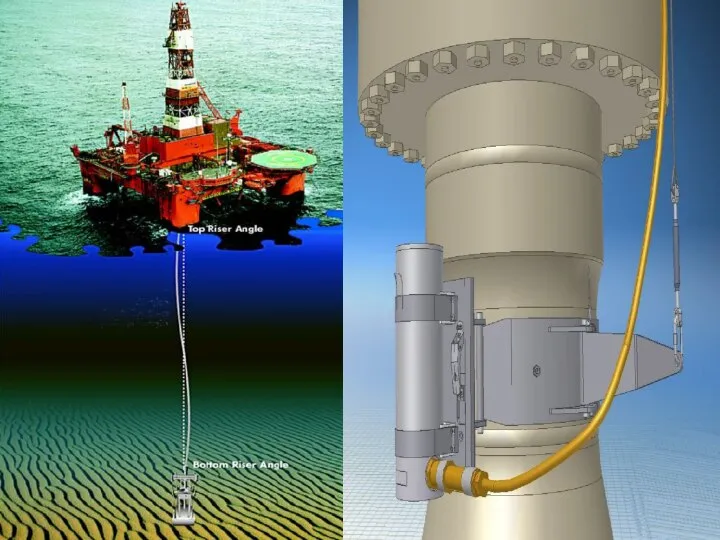
Слайд 36Electrical Riser Angle Sensor
Dynamic upper riser angle
A standard ERA sensor consists of
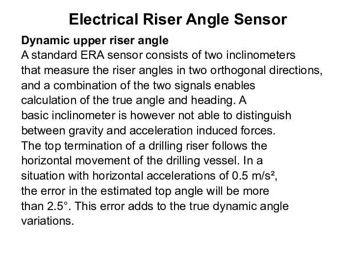
two inclinometers
that measure the riser angles in two orthogonal directions,
and a combination of the two signals enables
calculation of the true angle and heading. A
basic inclinometer is however not able to distinguish
between gravity and acceleration induced forces.
The top termination of a drilling riser follows the
horizontal movement of the drilling vessel. In a
situation with horizontal accelerations of 0.5 m/s²,
the error in the estimated top angle will be more
than 2.5°. This error adds to the true dynamic angle
variations.
Слайд 38DP Class requirements
IMO MSC/Circ 645 addresses redundancy and establishes 3 classes for
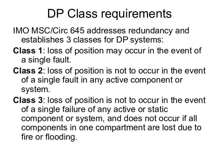
DP systems:
Class 1: loss of position may occur in the event of a single fault.
Class 2: loss of position is not to occur in the event of a single fault in any active component or system.
Class 3: loss of position is not to occur in the event of a single failure of any active or static component or system, and does not occur if all components in one compartment are lost due to fire or flooding.


 Магазин Золотой Ключик
 Приемы предупреждения и преодоления коммуникативных промахов и неудач
 Фотоэффект. Законы фотоэффекта
 Номенклатура дел
 Дорогу осилит идущий, а математику мыслящий.
 Птицеград
 Международная лаборатория функциональных материалов на основе стекла РХТУ им. Д.И. Менделеева Миусская пл. 9, 125047 Москва, Россия
 Урок 18
 Что такое ЕГЭ? Внеклассное мероприятие для 9-х классов: Тренинг с использованием программы «Физикон» «Подготовка к ЕГЭ по биологи
 Организация коррекционного процесса
 Презентация 2 [предыдущая]
 Марафон продающих текстов
 Памятка школьникам по противодействию терроризму
 Яйце-райце (2)
 012_VRU
 Олонецкая судостроительная верфь
 Волшебный шатер
 Основы религиозных культур и светской этики.
 Молодежный центр ЮИ СФУ
 Нейробика: аэробика для мозга
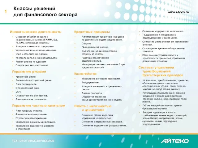 Классы решений для финансового сектора
 9 «В» Февраль 2012
 Социальное сиротство
 Cтратегия предприятияОАО «Дзержинское Оргстекло»в изменившихся экономических условиях
 Право на труд. Трудовые правоотношения
 Буддизм - религиозно-философское учение
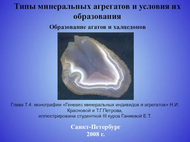 Типы минеральных агрегатов и условия их образования
 МОУ «Приволжская СОШ»