- Fiber-optic pressure instrument transducers

Содержание
- 2. Fiber-optic instrument transducers with elastic sensors Fig. 1 – Fiber-optic pressure instrument transducer design Fig. 2
- 3. Fiber optic pressure sensor using a mathematical model of the measurement process Fig. 3 – Fiber-optic
- 4. Fiber optic pressure sensor with automatic compensation for temperature error Fig. 5 – Fiber-optic pressure instrument
- 5. Fiber optic pressure sensor with integrated control Fig. 7 – Fiber-optic pressure instrument transducer construction Fig.
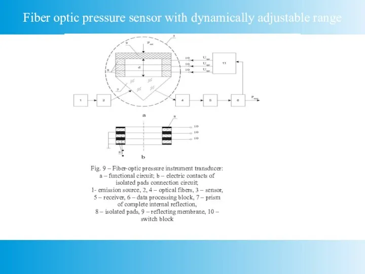
- 6. Fiber optic pressure sensor with dynamically adjustable range Fig. 9 – Fiber-optic pressure instrument transducer: a
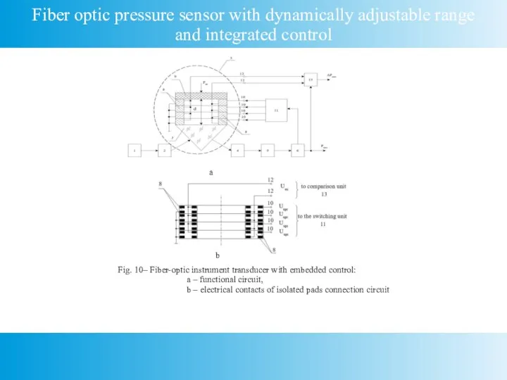
- 7. Fiber optic pressure sensor with dynamically adjustable range and integrated control a b Fig. 10– Fiber-optic
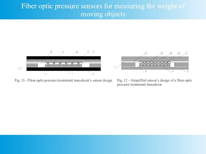
- 8. Fiber optic pressure sensors for measuring the weight of moving objects Fig. 11– Fiber-optic pressure instrument
- 10. Скачать презентацию
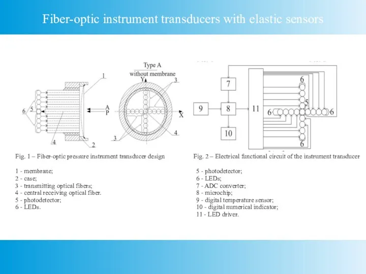
Слайд 2Fiber-optic instrument transducers with elastic sensors
Fig. 1 – Fiber-optic pressure instrument transducer
Fiber-optic instrument transducers with elastic sensors
Fig. 1 – Fiber-optic pressure instrument transducer
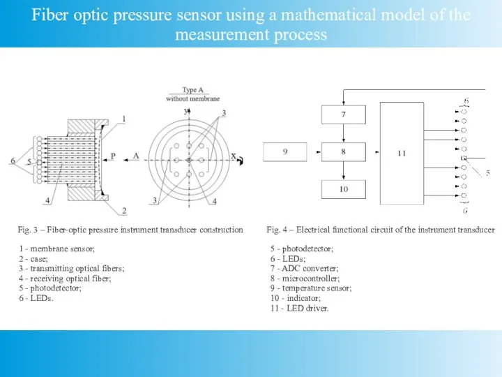
Слайд 3Fiber optic pressure sensor using a mathematical model of the measurement process
Fig.
Fiber optic pressure sensor using a mathematical model of the measurement process
Fig.
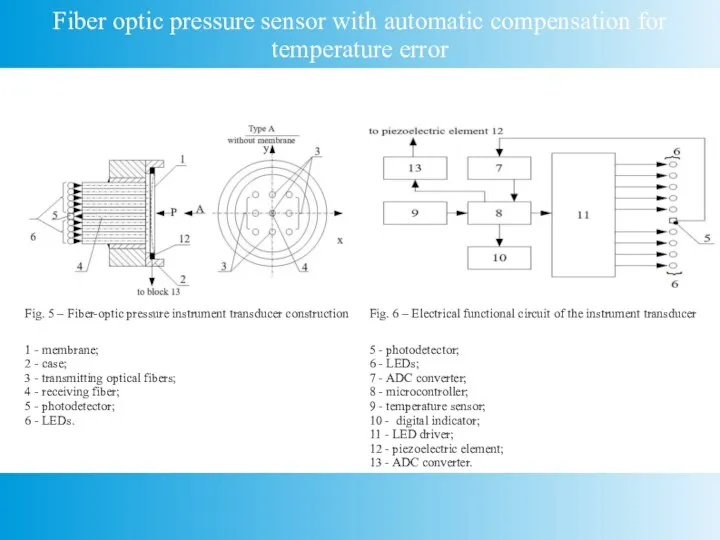
Слайд 4Fiber optic pressure sensor with automatic compensation for temperature error
Fig. 5 –
Fiber optic pressure sensor with automatic compensation for temperature error
Fig. 5 –
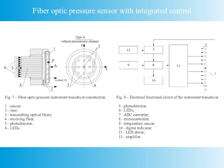
Слайд 5Fiber optic pressure sensor with integrated control
Fig. 7 – Fiber-optic pressure instrument
Fiber optic pressure sensor with integrated control
Fig. 7 – Fiber-optic pressure instrument
Слайд 6Fiber optic pressure sensor with dynamically adjustable range
Fig. 9 – Fiber-optic pressure
Fiber optic pressure sensor with dynamically adjustable range
Fig. 9 – Fiber-optic pressure
Слайд 7Fiber optic pressure sensor with dynamically adjustable range and integrated control
a
b
Fig. 10–
Fiber optic pressure sensor with dynamically adjustable range and integrated control
a
b
Fig. 10–
Слайд 8Fiber optic pressure sensors for measuring the weight of moving objects
Fig. 11–
Fiber optic pressure sensors for measuring the weight of moving objects
Fig. 11–
 Организация работы станции и путей не общего пользования, на основе подвода по графику порожнего подвижного состава
 Повторное использование асфальтобетона
  Инновационные технологии в работе специалистов социально-психологической службы по профилактике наркомании среди несовершенно
 История Нового Года
 Презентация на тему Ломоносов Михаил Васильевич (1711 - 1765)
  e2b2bf7752e93ea5095a63c392fa0930 (1)
 Презентация на тему Завоевания турками-османами Балканского полуострова
  Защита информации в век технологий
 Лас-Вегас – город азарта !
 Линейная функция и ее график 7 класс
 Презентация на тему История возникновения игрушки на Руси
 Городской семинар-практикум «Использование Smart-технологий в образовательном процессе как одно из условий повышения качества об
 Единые федеральные оценочные материалы (ЕФОМ) по экономике
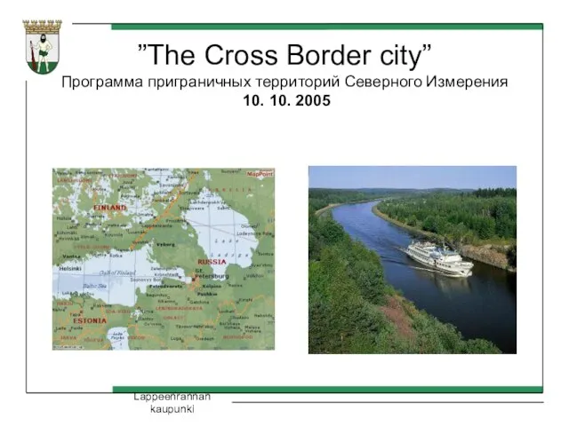 ”The Cross Border city”Программа приграничных территорий Северного Измерения 10. 10. 2005
 Водные ресурсы и их охрана
 День матери.Пусть мамы улыбаются
 Презентация 2
 Нуклеиновые кислоты: структура и функции
 Владимир Набоков
 Пензенский инновационный кластер универсальных компонентов и систем
 О системном подходе в информационном противодействии угрозам и вызовам безопасности Российской Федерации
 Билим Н.С._защита диплома
 Переработка стекла и производства архитектурно-строительных материалов из вторсырья
 ИСПОЛЬЗОВАНИЕ КОМПЬЮТЕРНЫХ ПРИЛОЖЕНИЙ ДЛЯ ОПТИМИЗАЦИИ ФИЗИКО-ХИМИЧЕСКИХ ИССЛЕДОВАНИЙ ГЕТЕРОГЕННЫХ ПРОЦЕССОВ ГАЗ-ТВЕРДОЕ
 Искусство, как способ познания мира
 Introduction to law Business Law
  Презентация опыт3
 Основные понятия корпуса