- Lifting and rigging OPERATIONS Instructor Andy Bruce

Содержание
- 2. Instructor Andy Bruce
- 3. AIMS AND OBJECTIVES Target Audience:- This 3 day course is intended for all categories of personnel
- 4. SAFETY MUSTER POINT FIRST AID MINIMUM PPE TO BE WORN QUARRY EDGES, ETC. COLOUR CODE MEAL
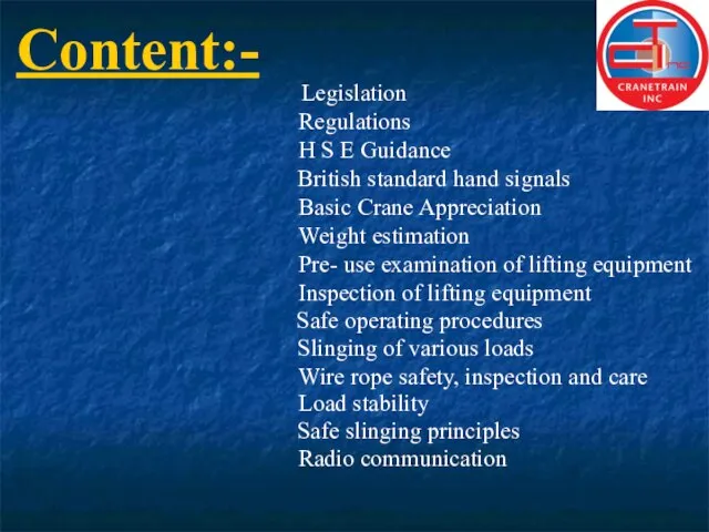
- 5. Content:- Legislation Regulations H S E Guidance Basic Crane Appreciation Pre- use examination of lifting equipment
- 6. L O L E R Reg`s Cont`d 6. Every employer shall reduce to as low as
- 7. L O L E R Loler regulations 1. Came into effect 5th Dec 1998. From this
- 8. L O L E R Reg`s Cont`d 11. Keeping of information. 9. Thorough examination and inspection.
- 9. LIFTING OPERATIONS APPLICABLE LEGISLATION HEALTH & SAFETY AT WORK etc 1974. MANAGEMENT OF HEALTH&SAFETY AT WORK
- 10. LIFTING OPERATIONS APPLICABLE LEGISLATION HEALTH & SAFETY AT WORK etc ACT 1974 EMPLOYERS RESPONSIBILITIES - It
- 11. 3 LIFTING OPERATIONS APPLICABLE LEGISLATION Management Of Health & Safety At Work Regs 1992 Requires employers
- 12. LIFTING OPERATIONS APPLICABLE LEGISLATION Management Of Health & Safety At Work Regs 1992 cont`d 4 Identify
- 13. 5 LIFTING OPERATIONS APPLICABLE LEGISLATION Provision And Use Of Work Equipment Regs 1992 Every employer shall:-
- 14. 6 LIFTING OPERATIONS APPLICABLE LEGISLATION Provision And Use Of Work Equipment Regs 1992 cont`d “suitable” means
- 15. 7 LIFTING OPERATIONS APPLICABLE LEGISLATION The use of work equipment is restricted to those persons given
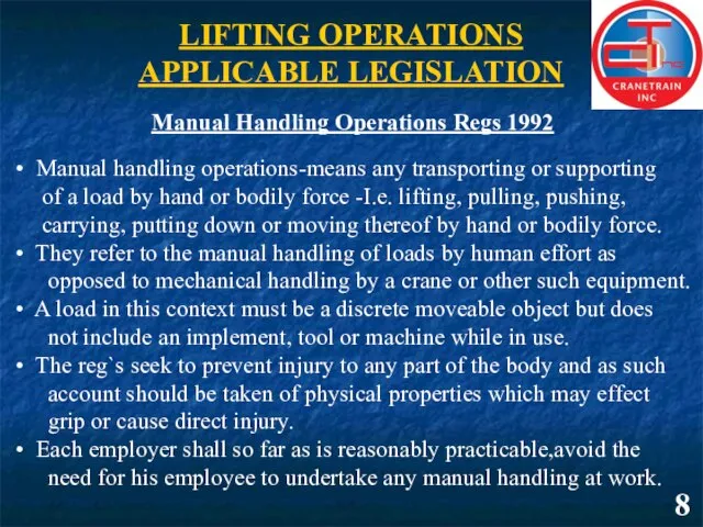
- 16. 8 LIFTING OPERATIONS APPLICABLE LEGISLATION Manual Handling Operations Regs 1992 Manual handling operations-means any transporting or
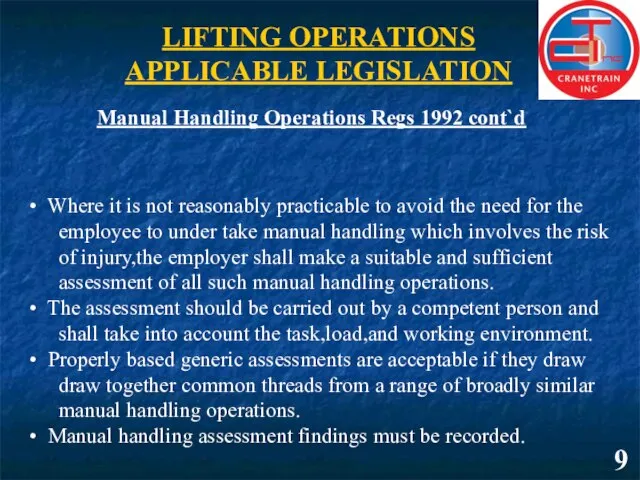
- 17. 9 LIFTING OPERATIONS APPLICABLE LEGISLATION Manual Handling Operations Regs 1992 cont`d Where it is not reasonably
- 18. LIFTING OPERATIONS APPLICABLE LEGISLATION 10 Lifting Operations And Lifting Equipment Regulations 1998 Regulation.1- Citation and commencement-lays
- 19. LIFTING OPERATIONS APPLICABLE LEGISLATION 11 Lifting Operations And Lifting Equipment Regulations 1998 cont`d Regulation. 7-Marking of
- 20. _____________________ TRAINING PRESENTATION
- 21. ________________________________________ TRAINING PRESENTATION
- 22. ____________________ TRAINING PRESENTATION
- 23. ____________________ TRAINING PRESENTATION
- 24. ______________
- 25. ____________________ TRAINING PRESENTATION
- 26. _____________________________________ TRAINING PRESENTATION
- 27. _____________________________________ TRAINING PRESENTATION
- 28. TRAINING PRESENTATION
- 29. _____________________________________ TRAINING PRESENTATION
- 30. _____________________________________ TRAINING PRESENTATION
- 31. _____________________________________ TRAINING PRESENTATION
- 32. _____________________________________ TRAINING PRESENTATION
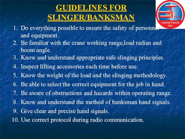
- 33. GUIDELINES FOR SLINGER/BANKSMAN 1. Do everything possible to ensure the safety of personnel and equipment. 2.
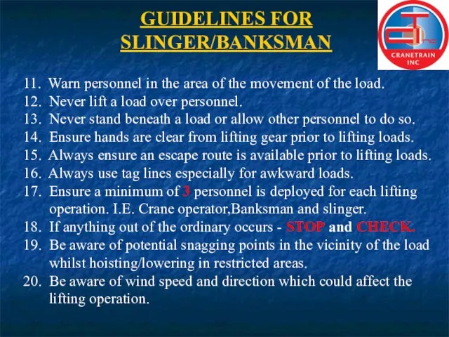
- 34. GUIDELINES FOR SLINGER/BANKSMAN 11. Warn personnel in the area of the movement of the load. 12.
- 35. _____________________________________ TRAINING PRESENTATION
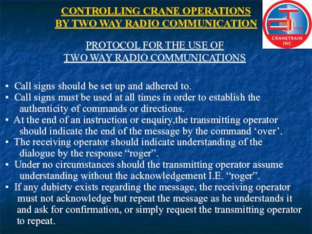
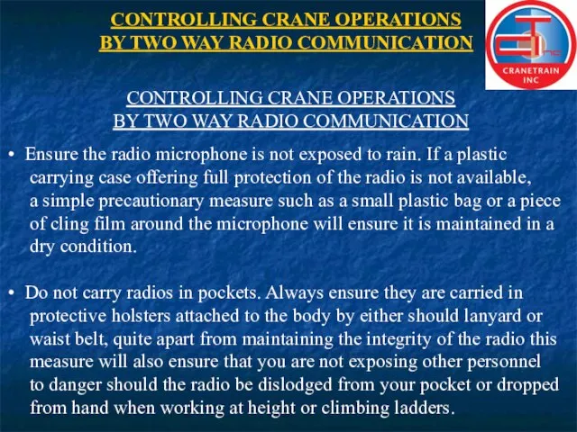
- 36. CONTROLLING CRANE OPERATIONS BY TWO WAY RADIO COMMUNICATION PROTOCOL FOR THE USE OF TWO WAY RADIO
- 37. CONTROLLING CRANE OPERATIONS BY TWO WAY RADIO COMMUNICATION PROTOCOL FOR THE USE OF TWO WAY RADIO
- 38. CONTROLLING CRANE OPERATIONS BY TWO WAY RADIO COMMUNICATION GENERAL INFORMATION ON THE USE OF TWO WAY
- 39. CONTROLLING CRANE OPERATIONS BY TWO WAY RADIO COMMUNICATION GENERAL INFORMATION ON THE USE OF TWO WAY
- 40. CONTROLLING CRANE OPERATIONS BY TWO WAY RADIO COMMUNICATION GENERAL INFORMATION ON THE USE OF TWO WAY
- 41. CONTROLLING CRANE OPERATIONS BY TWO WAY RADIO COMMUNICATION CONTROLLING CRANE OPERATIONS BY TWO WAY RADIO COMMUNICATION
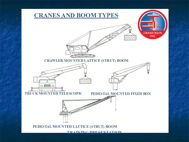
- 42. TRAINING PRESENTATION CRANES AND BOOM TYPES CRAWLER MOUNTED LATTICE (STRUT) BOOM TRUCK MOUNTED TELESCOPIC PEDESTAL MOUNTED
- 43. _____________________________________ TRAINING PRESENTATION
- 44. STABILITY STABILITY BASE CRAWLER CRANE CENTRE OF GRAVITY NO LOAD WITHOUT OUTRIGGERS WITH OUTRIGGERS _____________________________________
- 45. _____________________________________ TRAINING PRESENTATION STABILITY SAFE LOAD - CENTRE OF GRAVITY SUPPORTED OVER LOAD - CENTRE OF
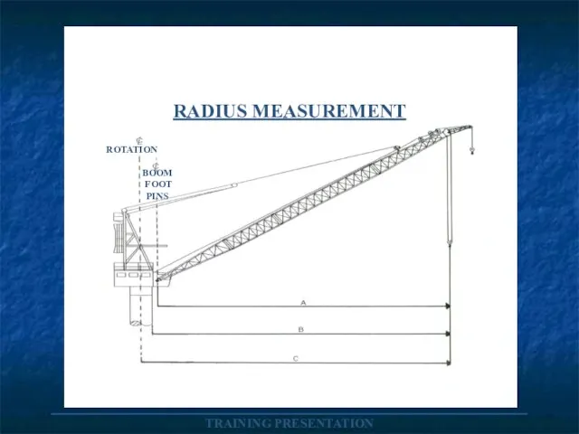
- 46. _____________________________________ TRAINING PRESENTATION RADIUS MEASUREMENT ROTATION BOOM FOOT PINS
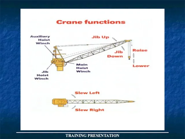
- 47. Angle Boom Boom Angle The angle from the horizontal (0°) at which the boom rests. 0°
- 48. Boom Sections A crane boom is usually in two sections: Upper and Lower. It may be
- 49. Fly Jib An extension fitted to the main boom/jib over which a secondary hoist system is
- 50. Outrigger Auxiliary equipment for extending the effective base of a crane to increase its stability.
- 51. Radius of Load /Operating Radius: The horizontal distance from the centre of rotation to a vertical
- 52. Mobile crawler
- 53. Mobile (Truck Mounted) Telescopic
- 54. Lattice boom
- 55. Articulated (knuckle-boom)
- 56. Fixed Box
- 57. GLOBAL DYNAMICS The effect of global dynamics will be significantly influenced by parameters such as:- The
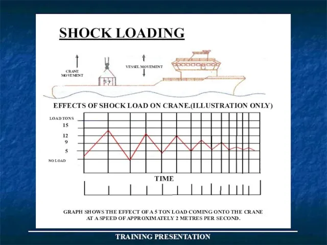
- 59. CRANE MOVEMENT VESSEL MOVEMENT NO LOAD 15 12 9 5 LOAD TONS SHOCK LOADING EFFECTS OF
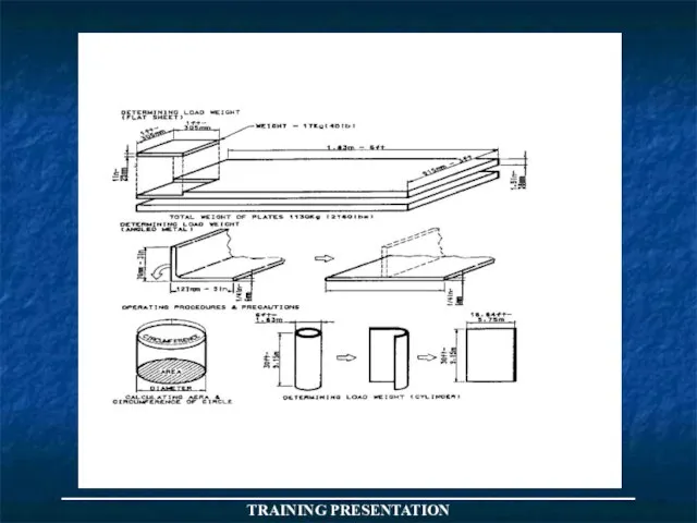
- 60. _____________________________________ TRAINING PRESENTATION ESTIMATION OF WEIGHT
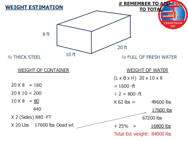
- 61. 8 ft 10 ft 20 ft WEIGHT ESTIMATION ½ THICK STEEL ½ FULL OF FRESH WATER
- 62. END OF DAY ONE
- 63. WIRE ROPES
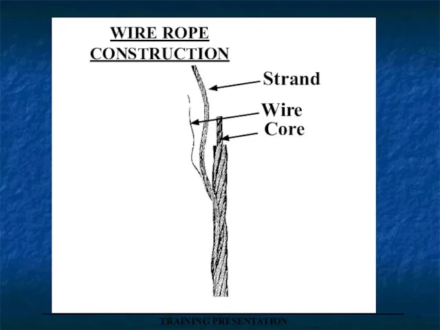
- 64. WIRE ROPE CONSTRUCTION Strand Wire Core _____________________________________ TRAINING PRESENTATION
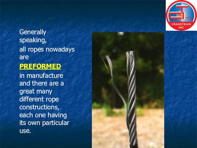
- 65. Generally speaking, all ropes nowadays are PREFORMED in manufacture and there are a great many different
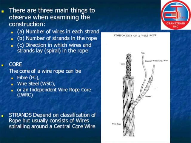
- 66. There are three main things to observe when examining the construction: (a) Number of wires in
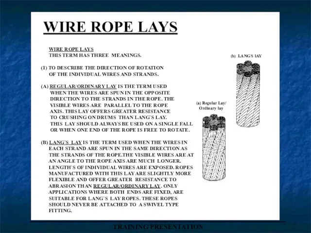
- 67. WIRE ROPE LAYS (b) LANGS lAY (a) Regular Lay/ Ordinary lay WIRE ROPE LAYS THIS TERM
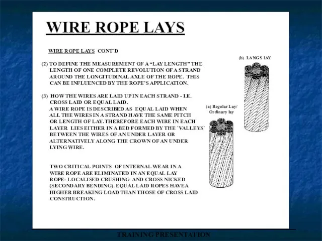
- 68. WIRE ROPE LAYS (b) LANGS lAY (a) Regular Lay/ Ordinary lay WIRE ROPE LAYS CONT`D (2)
- 69. FACTORS OF SAFETY NOTE:>Equipment used for personnel lifting appliances,E.G. personnel work baskets, carriers etc, Have a
- 70. WIRE ROPE REJECTION CRITERIA Consider which regulations apply to your work location and apply the relevant
- 71. _____________________________________ TRAINING PRESENTATION WIRE ROPE SLINGS . MULTI LEG SLINGS Two Leg Three Leg Four Leg
- 72. _____________________________________ TRAINING PRESENTATION TYPICAL SLING CONFIGURATIONS SINGLE LEG ENDLESS DOUBLE LEG WITH CLUTCHES THREE LEGS FOUR
- 73. _____________________________________ TRAINING PRESENTATION
- 74. _____________________________________ TRAINING PRESENTATION THE SAFE USE OF WIRE ROPE SLINGS WIRE ROPE SLINGS ARE GENERALLY MANUFACTURED
- 75. _____________________________________ TRAINING PRESENTATION
- 76. _____________________________________ TRAINING PRESENTATION SLING ANGLES 0° 30° 60° 90° 120° 0.5 te each sling 0.53 te
- 77. _____________________________________ TRAINING PRESENTATION W X L No X H
- 78. _____________________________________ TRAINING PRESENTATION EYEBOLTS-(BS 4278) COLLAR EYEBOLT DYNAMO EYEBOLT EYEBOLT WITH LINK SHOULD BE USED FOR
- 79. _____________________________________ TRAINING PRESENTATION EYEBOLTS DYNAMO COLLAR COLLAR WITH LINK . SAME PLANE CORRECT AGAINST PLANE INCORRECT
- 80. _____________________________________ TRAINING PRESENTATION
- 81. _____________________________________ TRAINING PRESENTATION CORRECT/INCORRECT METHOD OF SLINGING WHEN USING PAIRS OF SLINGS NOTE:- INCREASE IN LOAD
- 82. SINGLE VERTICAL LIFT 0º ONLY _____________________________________ TRAINING PRESENTATION DYNAMO EYEBOLT
- 83. _____________________________________ TRAINING PRESENTATION EYEBOLT CHART RECOMMENDED S.W.L. LOADS
- 84. _____________________________________ TRAINING PRESENTATION
- 85. _____________________________________ TRAINING PRESENTATION
- 86. _____________________________________ TRAINING PRESENTATION SHACKLES PRE - USE INSPECTION Select correct type shackle for the job in
- 87. _____________________________________ TRAINING PRESENTATION SHACKLES PRE - USE INSPECTION (CONT`D) Check alignment of pin holes - the
- 88. _____________________________________ TRAINING PRESENTATION SAFE WORKING LOADS OF ALLOY SHACKLES (U.S.FEDERAL SPEC.) ANCHOR SHACKLE WITH SCREW PIN
- 89. END OF DAY TWO
- 90. _____________________________________ TRAINING PRESENTATION
- 91. _____________________________________ TRAINING PRESENTATION SUBSTANCES
- 92. _____________________________________ TRAINING PRESENTATION
- 93. _____________________________________ TRAINING PRESENTATION SAFE WORKING LOADS OF MAN-MADE FIBRE SLINGS VERTICAL CHOKER BASKET BASKET 90° BASKET
- 94. PLATE CLAMPS TWO BASIC TYPES AVAILABLE Horizontal clamps can only be used in pairs. Universal clamps
- 95. WIRE ROPE HOISTS STANDARD ROPE HOIST TWO TYPES OF APPLICATION - LIFTING APPLICATION - PULLING APPLICATION
- 96. _____________________________________ TRAINING PRESENTATION SWL OF TURNBUCKLES/ RIGGING SCREWS BS 4429 DIA (mm) SWL 10 300KG 12
- 97. _____________________________________ TRAINING PRESENTATION WIRE ROPE CLIPS (BULLDOGS)
- 98. _____________________________________ TRAINING PRESENTATION LINE SPEED AND LINE PULL ROOT DIAMETER FIRST LAYER DIAMETER LAST LAYER NEVER
- 99. _____________________________________ TRAINING PRESENTATION REEVING WINCH WITH SINGLE LINE PULL OF 4 TONS ONE SHEAVE SINGLE PART
- 100. _____________________________________ TRAINING PRESENTATION Angle of fleet The fleet angle is the angle formed between a line
- 101. ROPE BLOCKS _____________________________________ TRAINING PRESENTATION Load on anchorage 1 tonne Load on anchorage 2 tonne Load
- 102. _____________________________________ TRAINING PRESENTATION ROPE BLOCKS CONT`D HOWEVER,IN CALCULATING THE EFFORT REQUIRED TO LIFT THE LOAD AND
- 103. TABLE LOADINGS ARRANGEMENT SINGLE 2 SINGLE DOUBLE AND SINGLE 2 DOUBLE 2 TREBLE DOUBLE AND TREBLE
- 104. THE FOLLOWING CHART INDICATES THE FACTOR TO BE MULTIPLIED BY THE LINE PULL TO OBTAIN THE
- 105. 450 Kgs _____________________________________ TRAINING PRESENTATION
- 106. _____________________________________ TRAINING PRESENTATION 1000 Kgs
- 107. SINGLE VERTICAL CHOKE _____________________________________ TRAINING PRESENTATION
- 108. DOUBLE WRAP CHOKE HITCH 0º _____________________________________ TRAINING PRESENTATION
- 109. _____________________________________ TRAINING PRESENTATION DOUBLE WRAP CHOKE HITCH AT 90º THIS HITCH COMPRESSES THE LOAD AND PREVENTS
- 110. _____________________________________ TRAINING PRESENTATION FURTHER EXAMPLES THAT SHOW INCREASED LOADING EFFECTS ON ROPES SUITABLE TIMBER PACKING SUITABLE
- 112. _____________________________________ TRAINING PRESENTATION
- 113. ______________________________________________________________ TRAINING PRESENTATION GUNNEBO HOOKS
- 114. _____________________________________ TRAINING PRESENTATION RIGHT AND WRONG PULLEY GROOVES WRONG PULLEY GROOVE TOO NARROW WRONG PULLEY GROOVE
- 115. ROPE ANCHORAGE LOCATION PLAIN DRUM START ROPE AT RIGHT FLANGE RIGHT HAND RIGHT HAND LAY ROPE
- 116. When spooling wire rope from a wooden drum onto the winch drum, avoid reverse bending which
- 117. _____________________________________ TRAINING PRESENTATION MEASUREMENT OF ROPE DIAMETERS CORRECT WAY THIS GIVES CORRECT DIAMETER INCORRECT WAY THIS
- 118. _____________________________________ TRAINING PRESENTATION LOCATION OF ATTACHMENT TO JIB OR HOOK BLOCK WEDGE SOCKET DEAD END OF
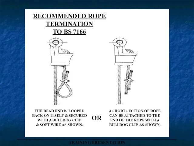
- 119. _____________________________________ TRAINING PRESENTATION RECOMMENDED ROPE TERMINATION TO BS 7166 THE DEAD END IS LOOPED BACK ON
- 120. _____________________________________ TRAINING PRESENTATION
- 121. OPERATIONAL ENVELOPE The FROG has been designed to ensure passengers safely even when operating in relatively
- 122. TRANSFER LOG As for most potentially hazardous operations carried out in the offshore Environment, the safety
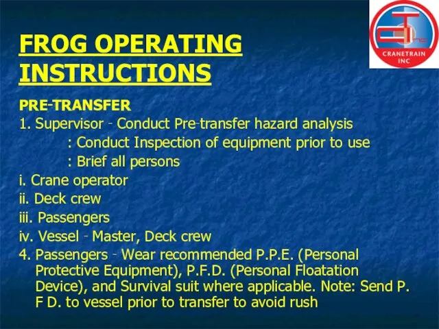
- 123. FROG OPERATING INSTRUCTIONS PRE‑TRANSFER 1. Supervisor ‑ Conduct Pre‑transfer hazard analysis : Conduct Inspection of equipment
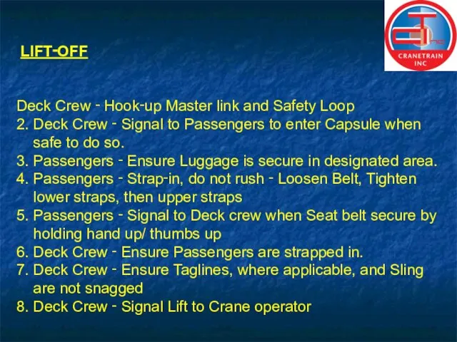
- 124. LIFT‑OFF Deck Crew ‑ Hook‑up Master link and Safety Loop 2. Deck Crew ‑ Signal to
- 125. LANDING 1. Crane Op. ‑ All raising and lowering must be over water 2. Crane Op.
- 127. TAG LINES Tag lines (hand line) are not supplied with the FROG. However if users wish
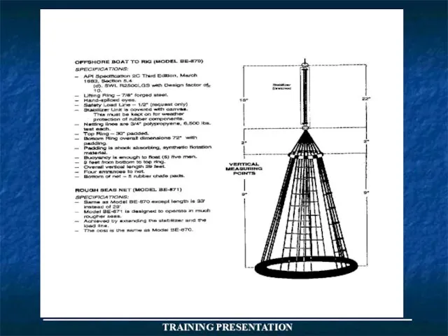
- 130. APPROVED PERSONNEL NETS _____________________________________ TRAINING PRESENTATION (Billy Pugh)
- 131. ARE THERE ANY QUESTIONS?
- 133. Скачать презентацию

Слайд 3AIMS AND OBJECTIVES
Target Audience:-
This 3 day course is intended for all categories
AIMS AND OBJECTIVES
Target Audience:-
This 3 day course is intended for all categories
Слайд 4SAFETY
MUSTER POINT
FIRST AID
MINIMUM PPE TO BE WORN
QUARRY EDGES,
SAFETY
MUSTER POINT
FIRST AID
MINIMUM PPE TO BE WORN
QUARRY EDGES,

Слайд 5Content:-
Legislation
Regulations
H S E Guidance
Basic Crane Appreciation
Pre- use examination of lifting equipment
Inspection of
Content:-
Legislation
Regulations
H S E Guidance
Basic Crane Appreciation
Pre- use examination of lifting equipment
Inspection of
Слайд 6L O L E R
Reg`s Cont`d
6. Every employer shall reduce to as
L O L E R
Reg`s Cont`d
6. Every employer shall reduce to as

Слайд 7L O L E R
Loler regulations
1. Came into effect 5th Dec
L O L E R
Loler regulations
1. Came into effect 5th Dec

Слайд 8L O L E R
Reg`s Cont`d
11. Keeping of information.
9. Thorough examination and
L O L E R
Reg`s Cont`d
11. Keeping of information.
9. Thorough examination and

Слайд 9LIFTING OPERATIONS
APPLICABLE LEGISLATION
HEALTH & SAFETY AT WORK etc 1974.
MANAGEMENT OF
LIFTING OPERATIONS
APPLICABLE LEGISLATION
HEALTH & SAFETY AT WORK etc 1974.
MANAGEMENT OF

Слайд 10LIFTING OPERATIONS
APPLICABLE LEGISLATION
HEALTH & SAFETY AT WORK etc ACT 1974
EMPLOYERS RESPONSIBILITIES
-
LIFTING OPERATIONS
APPLICABLE LEGISLATION
HEALTH & SAFETY AT WORK etc ACT 1974
EMPLOYERS RESPONSIBILITIES
-

Слайд 113
LIFTING OPERATIONS
APPLICABLE LEGISLATION
Management Of Health & Safety At Work Regs 1992
Requires
3
LIFTING OPERATIONS
APPLICABLE LEGISLATION
Management Of Health & Safety At Work Regs 1992
Requires

Слайд 12LIFTING OPERATIONS
APPLICABLE LEGISLATION
Management Of Health & Safety At Work Regs 1992 cont`d
4
Identify
LIFTING OPERATIONS
APPLICABLE LEGISLATION
Management Of Health & Safety At Work Regs 1992 cont`d
4
Identify

Слайд 135
LIFTING OPERATIONS
APPLICABLE LEGISLATION
Provision And Use Of Work Equipment Regs 1992
Every employer
5
LIFTING OPERATIONS
APPLICABLE LEGISLATION
Provision And Use Of Work Equipment Regs 1992
Every employer

Слайд 146
LIFTING OPERATIONS
APPLICABLE LEGISLATION
Provision And Use Of Work Equipment Regs 1992 cont`d
“suitable”
6
LIFTING OPERATIONS
APPLICABLE LEGISLATION
Provision And Use Of Work Equipment Regs 1992 cont`d
“suitable”

Слайд 157
LIFTING OPERATIONS
APPLICABLE LEGISLATION
The use of work equipment is restricted to those
7
LIFTING OPERATIONS
APPLICABLE LEGISLATION
The use of work equipment is restricted to those

Слайд 168
LIFTING OPERATIONS
APPLICABLE LEGISLATION
Manual Handling Operations Regs 1992
Manual handling operations-means any transporting
8
LIFTING OPERATIONS
APPLICABLE LEGISLATION
Manual Handling Operations Regs 1992
Manual handling operations-means any transporting
Слайд 179
LIFTING OPERATIONS
APPLICABLE LEGISLATION
Manual Handling Operations Regs 1992 cont`d
Where it is not
9
LIFTING OPERATIONS
APPLICABLE LEGISLATION
Manual Handling Operations Regs 1992 cont`d
Where it is not
Слайд 18LIFTING OPERATIONS
APPLICABLE LEGISLATION
10
Lifting Operations And Lifting Equipment Regulations 1998
Regulation.1- Citation and
LIFTING OPERATIONS
APPLICABLE LEGISLATION
10
Lifting Operations And Lifting Equipment Regulations 1998
Regulation.1- Citation and

Слайд 19LIFTING OPERATIONS
APPLICABLE LEGISLATION
11
Lifting Operations And Lifting Equipment Regulations 1998 cont`d
Regulation. 7-Marking of
LIFTING OPERATIONS
APPLICABLE LEGISLATION
11
Lifting Operations And Lifting Equipment Regulations 1998 cont`d
Regulation. 7-Marking of

Слайд 20_____________________
TRAINING PRESENTATION
_____________________
TRAINING PRESENTATION

Слайд 21________________________________________
TRAINING PRESENTATION
________________________________________
TRAINING PRESENTATION
Слайд 22____________________
TRAINING PRESENTATION
____________________
TRAINING PRESENTATION
Слайд 23____________________
TRAINING PRESENTATION
____________________
TRAINING PRESENTATION
Слайд 24______________
______________
Слайд 25____________________
TRAINING PRESENTATION
____________________
TRAINING PRESENTATION
Слайд 26_____________________________________
TRAINING PRESENTATION
_____________________________________
TRAINING PRESENTATION
Слайд 27_____________________________________ TRAINING PRESENTATION
_____________________________________ TRAINING PRESENTATION
Слайд 28TRAINING PRESENTATION
TRAINING PRESENTATION
Слайд 29_____________________________________
TRAINING PRESENTATION
_____________________________________
TRAINING PRESENTATION
Слайд 30_____________________________________
TRAINING PRESENTATION
_____________________________________
TRAINING PRESENTATION
Слайд 31_____________________________________
TRAINING PRESENTATION
_____________________________________
TRAINING PRESENTATION
Слайд 32_____________________________________
TRAINING PRESENTATION
_____________________________________
TRAINING PRESENTATION
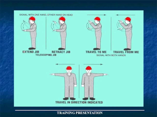
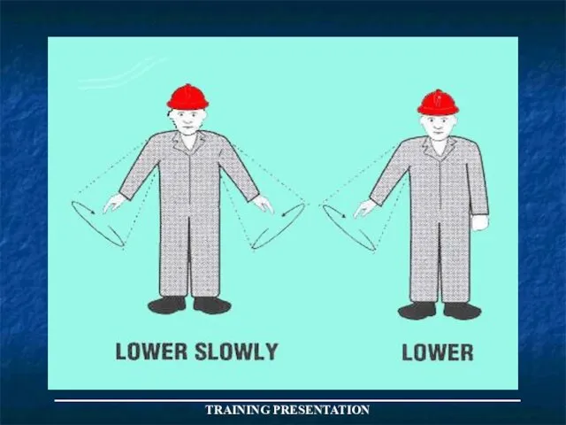
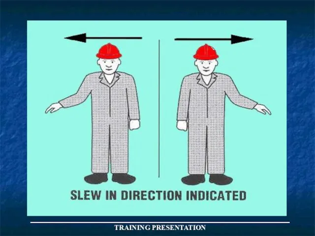
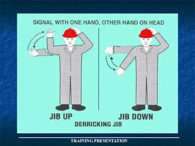
Слайд 33GUIDELINES FOR
SLINGER/BANKSMAN
1. Do everything possible to ensure the safety of
GUIDELINES FOR
SLINGER/BANKSMAN
1. Do everything possible to ensure the safety of
Слайд 34GUIDELINES FOR
SLINGER/BANKSMAN
11. Warn personnel in the area of the movement of
GUIDELINES FOR
SLINGER/BANKSMAN
11. Warn personnel in the area of the movement of
Слайд 35_____________________________________
TRAINING PRESENTATION
_____________________________________
TRAINING PRESENTATION
Слайд 36CONTROLLING CRANE OPERATIONS
BY TWO WAY RADIO COMMUNICATION
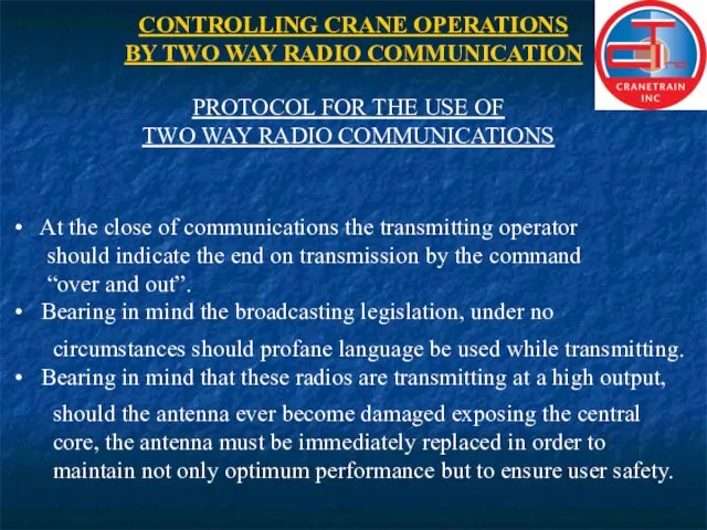
PROTOCOL FOR THE USE OF
TWO
CONTROLLING CRANE OPERATIONS
BY TWO WAY RADIO COMMUNICATION
PROTOCOL FOR THE USE OF
TWO
Слайд 37CONTROLLING CRANE OPERATIONS
BY TWO WAY RADIO COMMUNICATION
PROTOCOL FOR THE USE OF
TWO
CONTROLLING CRANE OPERATIONS
BY TWO WAY RADIO COMMUNICATION
PROTOCOL FOR THE USE OF
TWO
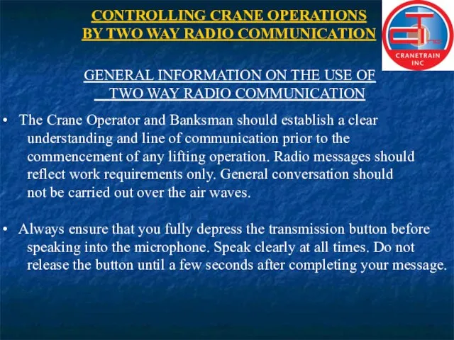
Слайд 38CONTROLLING CRANE OPERATIONS
BY TWO WAY RADIO COMMUNICATION
GENERAL INFORMATION ON THE USE OF
CONTROLLING CRANE OPERATIONS
BY TWO WAY RADIO COMMUNICATION
GENERAL INFORMATION ON THE USE OF
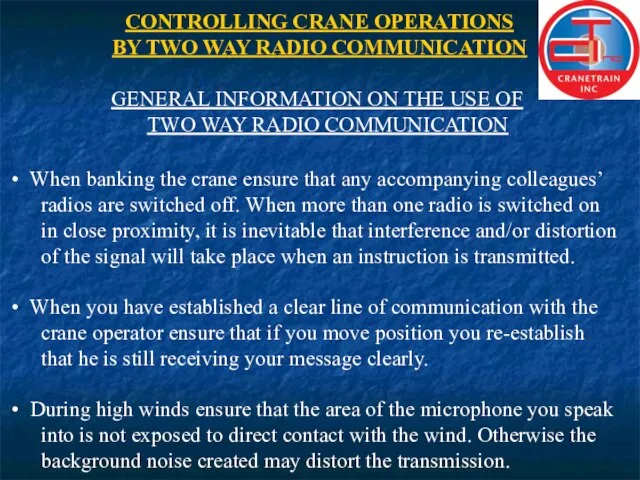
Слайд 39CONTROLLING CRANE OPERATIONS
BY TWO WAY RADIO COMMUNICATION
GENERAL INFORMATION ON THE USE OF
CONTROLLING CRANE OPERATIONS
BY TWO WAY RADIO COMMUNICATION
GENERAL INFORMATION ON THE USE OF
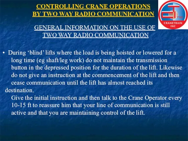
Слайд 40CONTROLLING CRANE OPERATIONS
BY TWO WAY RADIO COMMUNICATION
GENERAL INFORMATION ON THE USE OF
CONTROLLING CRANE OPERATIONS
BY TWO WAY RADIO COMMUNICATION
GENERAL INFORMATION ON THE USE OF
Слайд 41CONTROLLING CRANE OPERATIONS
BY TWO WAY RADIO COMMUNICATION
CONTROLLING CRANE OPERATIONS
BY TWO WAY RADIO
CONTROLLING CRANE OPERATIONS
BY TWO WAY RADIO COMMUNICATION
CONTROLLING CRANE OPERATIONS
BY TWO WAY RADIO
Слайд 42TRAINING PRESENTATION
CRANES AND BOOM TYPES
CRAWLER MOUNTED LATTICE (STRUT) BOOM
TRUCK MOUNTED TELESCOPIC
PEDESTAL MOUNTED
TRAINING PRESENTATION
CRANES AND BOOM TYPES
CRAWLER MOUNTED LATTICE (STRUT) BOOM
TRUCK MOUNTED TELESCOPIC
PEDESTAL MOUNTED
Слайд 43_____________________________________
TRAINING PRESENTATION
_____________________________________
TRAINING PRESENTATION
Слайд 44STABILITY
STABILITY BASE CRAWLER CRANE
CENTRE OF GRAVITY NO LOAD
WITHOUT
OUTRIGGERS
WITH
OUTRIGGERS
_____________________________________
STABILITY
STABILITY BASE CRAWLER CRANE
CENTRE OF GRAVITY NO LOAD
WITHOUT
OUTRIGGERS
WITH
OUTRIGGERS
_____________________________________

Слайд 45_____________________________________
TRAINING PRESENTATION
STABILITY
SAFE LOAD - CENTRE OF GRAVITY SUPPORTED
OVER LOAD - CENTRE OF
_____________________________________
TRAINING PRESENTATION
STABILITY
SAFE LOAD - CENTRE OF GRAVITY SUPPORTED
OVER LOAD - CENTRE OF

Слайд 46_____________________________________
TRAINING PRESENTATION
RADIUS MEASUREMENT
ROTATION
BOOM
FOOT
PINS
_____________________________________
TRAINING PRESENTATION
RADIUS MEASUREMENT
ROTATION
BOOM
FOOT
PINS
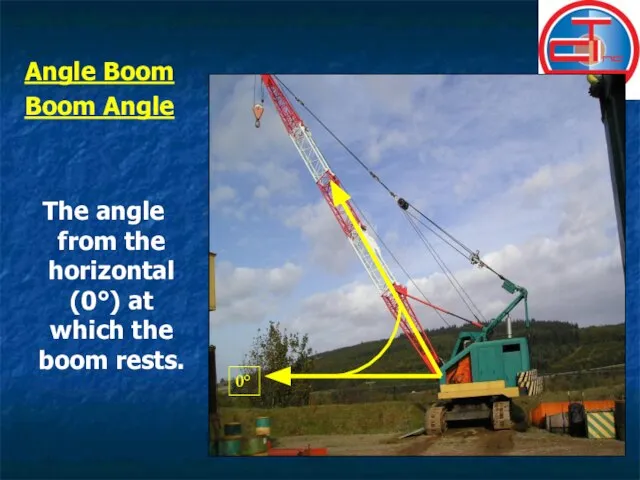
Слайд 47Angle Boom
Boom Angle
The angle from the horizontal (0°) at which the
Angle Boom
Boom Angle
The angle from the horizontal (0°) at which the
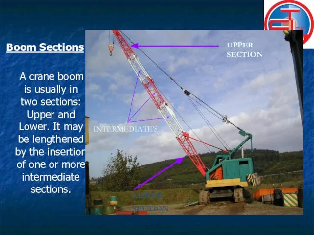
Слайд 48Boom Sections
A crane boom is usually in two sections: Upper and Lower.
Boom Sections
A crane boom is usually in two sections: Upper and Lower.
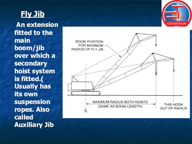
Слайд 49Fly Jib
An extension fitted to the main boom/jib over which
Fly Jib
An extension fitted to the main boom/jib over which
Слайд 50 Outrigger Auxiliary equipment for extending the effective base of a crane
Outrigger Auxiliary equipment for extending the effective base of a crane

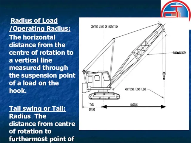
Слайд 51 Radius of Load /Operating Radius:
The horizontal distance from the
Radius of Load /Operating Radius:
The horizontal distance from the
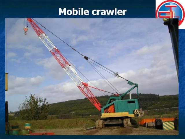
Слайд 52Mobile crawler
Mobile crawler
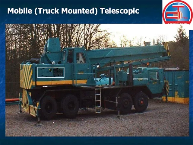
Слайд 53Mobile (Truck Mounted) Telescopic
Mobile (Truck Mounted) Telescopic
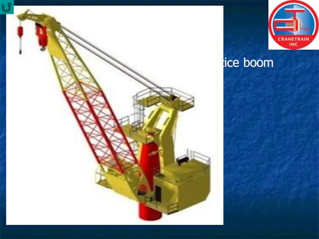
Слайд 54 Lattice boom
Lattice boom
Слайд 55Articulated (knuckle-boom)
Articulated (knuckle-boom)

Слайд 56Fixed Box
Fixed Box

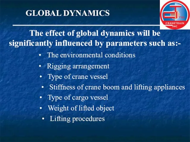
Слайд 57GLOBAL DYNAMICS
The effect of global dynamics will be
significantly influenced by parameters such
GLOBAL DYNAMICS
The effect of global dynamics will be
significantly influenced by parameters such

Слайд 59CRANE
MOVEMENT
VESSEL MOVEMENT
NO LOAD
15
12
9
5
LOAD TONS
SHOCK LOADING
EFFECTS OF SHOCK LOAD ON CRANE.(ILLUSTRATION
CRANE
MOVEMENT
VESSEL MOVEMENT
NO LOAD
15
12
9
5
LOAD TONS
SHOCK LOADING
EFFECTS OF SHOCK LOAD ON CRANE.(ILLUSTRATION
Слайд 60_____________________________________
TRAINING PRESENTATION
ESTIMATION OF WEIGHT
_____________________________________
TRAINING PRESENTATION
ESTIMATION OF WEIGHT
Слайд 618 ft
10 ft
20 ft
WEIGHT ESTIMATION
½ THICK STEEL
½ FULL OF FRESH WATER
WEIGHT OF
8 ft
10 ft
20 ft
WEIGHT ESTIMATION
½ THICK STEEL
½ FULL OF FRESH WATER
WEIGHT OF
Слайд 62END
OF
DAY ONE
END
OF
DAY ONE

Слайд 63WIRE ROPES
WIRE ROPES

Слайд 64WIRE ROPE
CONSTRUCTION
Strand
Wire
Core
_____________________________________
TRAINING PRESENTATION
WIRE ROPE
CONSTRUCTION
Strand
Wire
Core
_____________________________________
TRAINING PRESENTATION
Слайд 65
Generally speaking,
all ropes nowadays are
PREFORMED
in manufacture and there are
Generally speaking,
all ropes nowadays are
PREFORMED
in manufacture and there are
Слайд 66There are three main things to observe when examining the construction:
(a) Number
There are three main things to observe when examining the construction:
(a) Number
Слайд 67WIRE ROPE LAYS
(b) LANGS lAY
(a) Regular Lay/
Ordinary lay
WIRE ROPE LAYS
THIS
WIRE ROPE LAYS
(b) LANGS lAY
(a) Regular Lay/
Ordinary lay
WIRE ROPE LAYS
THIS
Слайд 68WIRE ROPE LAYS
(b) LANGS lAY
(a) Regular Lay/
Ordinary lay
WIRE ROPE LAYS CONT`D
(2)
WIRE ROPE LAYS
(b) LANGS lAY
(a) Regular Lay/
Ordinary lay
WIRE ROPE LAYS CONT`D
(2)
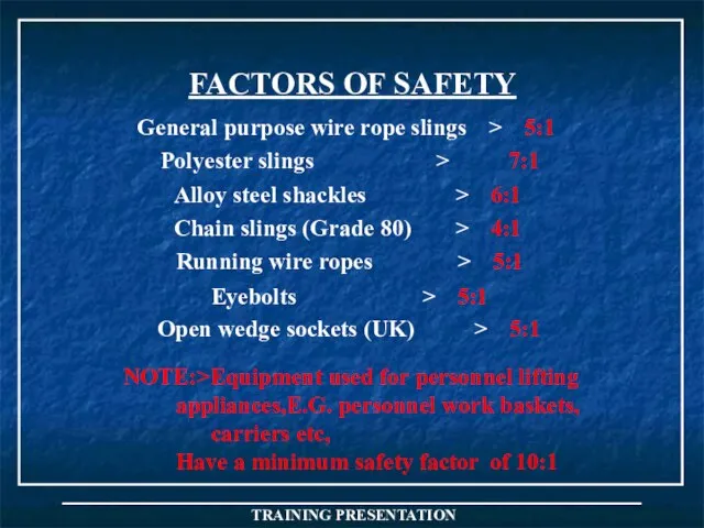
Слайд 69FACTORS OF SAFETY
NOTE:>Equipment used for personnel lifting
appliances,E.G. personnel work baskets,
carriers
FACTORS OF SAFETY
NOTE:>Equipment used for personnel lifting
appliances,E.G. personnel work baskets,
carriers
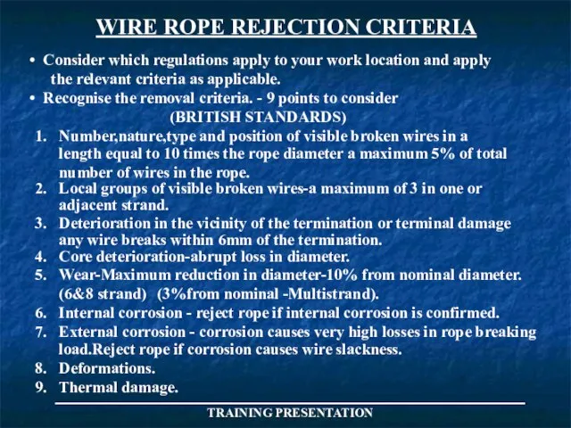
Слайд 70WIRE ROPE REJECTION CRITERIA
Consider which regulations apply to your work location
WIRE ROPE REJECTION CRITERIA
Consider which regulations apply to your work location
Слайд 71_____________________________________
TRAINING PRESENTATION
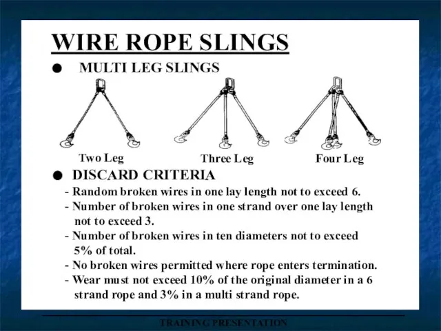
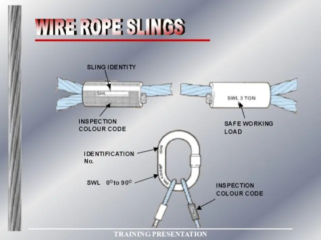
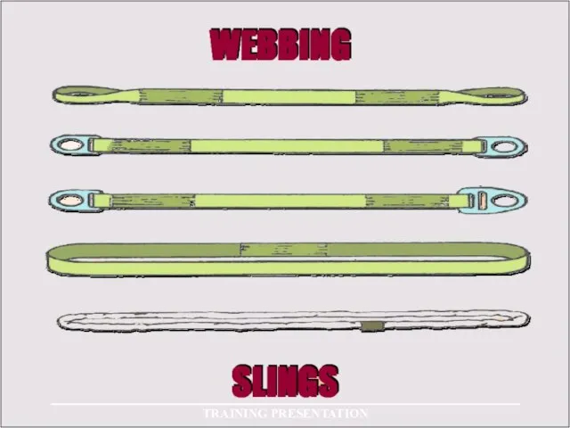
WIRE ROPE SLINGS
. MULTI LEG SLINGS
Two Leg
Three Leg
Four Leg
. DISCARD CRITERIA
-
_____________________________________
TRAINING PRESENTATION
WIRE ROPE SLINGS
. MULTI LEG SLINGS
Two Leg
Three Leg
Four Leg
. DISCARD CRITERIA
-
Слайд 72_____________________________________
TRAINING PRESENTATION
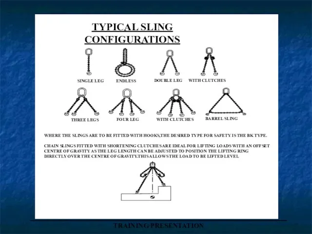
TYPICAL SLING
CONFIGURATIONS
SINGLE LEG
ENDLESS
DOUBLE LEG
WITH CLUTCHES
THREE LEGS
FOUR LEG
BARREL SLING
WITH CLUTCHES
WHERE THE
_____________________________________
TRAINING PRESENTATION
TYPICAL SLING
CONFIGURATIONS
SINGLE LEG
ENDLESS
DOUBLE LEG
WITH CLUTCHES
THREE LEGS
FOUR LEG
BARREL SLING
WITH CLUTCHES
WHERE THE
Слайд 73_____________________________________
TRAINING PRESENTATION
_____________________________________
TRAINING PRESENTATION
Слайд 74_____________________________________
TRAINING PRESENTATION
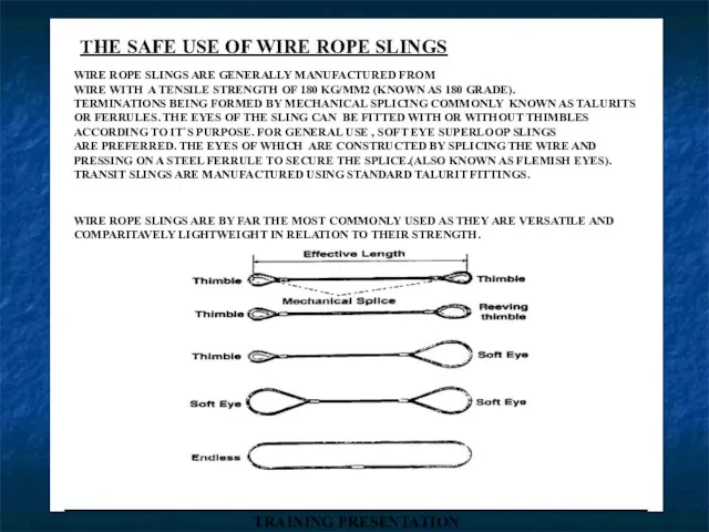
THE SAFE USE OF WIRE ROPE SLINGS
WIRE ROPE SLINGS ARE GENERALLY
_____________________________________
TRAINING PRESENTATION
THE SAFE USE OF WIRE ROPE SLINGS
WIRE ROPE SLINGS ARE GENERALLY
Слайд 75_____________________________________
TRAINING PRESENTATION
_____________________________________
TRAINING PRESENTATION
Слайд 76_____________________________________
TRAINING PRESENTATION
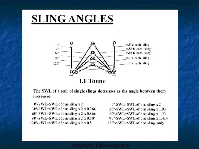
SLING ANGLES
0°
30°
60°
90°
120°
0.5 te each sling
0.53 te each
_____________________________________
TRAINING PRESENTATION
SLING ANGLES
0°
30°
60°
90°
120°
0.5 te each sling
0.53 te each
Слайд 77_____________________________________
TRAINING PRESENTATION
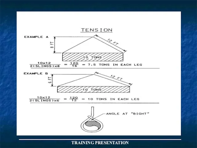
W X L
No X H
_____________________________________
TRAINING PRESENTATION
W X L
No X H
Слайд 78_____________________________________
TRAINING PRESENTATION
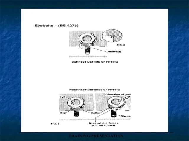
EYEBOLTS-(BS 4278)
COLLAR EYEBOLT
DYNAMO EYEBOLT
EYEBOLT
WITH LINK
SHOULD BE USED FOR
VERTICAL LIFTS
OR
_____________________________________
TRAINING PRESENTATION
EYEBOLTS-(BS 4278)
COLLAR EYEBOLT
DYNAMO EYEBOLT
EYEBOLT
WITH LINK
SHOULD BE USED FOR
VERTICAL LIFTS
OR

Слайд 79_____________________________________
TRAINING PRESENTATION
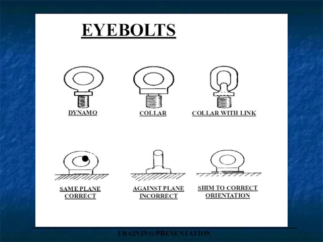
EYEBOLTS
DYNAMO
COLLAR
COLLAR WITH LINK
.
SAME PLANE
CORRECT
AGAINST PLANE
INCORRECT
SHIM TO CORRECT
ORIENTATION
_____________________________________
TRAINING PRESENTATION
EYEBOLTS
DYNAMO
COLLAR
COLLAR WITH LINK
.
SAME PLANE
CORRECT
AGAINST PLANE
INCORRECT
SHIM TO CORRECT
ORIENTATION
Слайд 80_____________________________________
TRAINING PRESENTATION
_____________________________________
TRAINING PRESENTATION
Слайд 81_____________________________________
TRAINING PRESENTATION
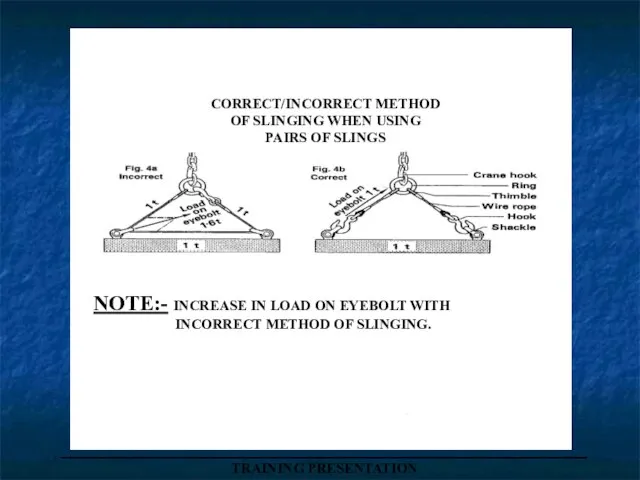
CORRECT/INCORRECT METHOD
OF SLINGING WHEN USING
PAIRS OF SLINGS
NOTE:- INCREASE IN LOAD ON
_____________________________________
TRAINING PRESENTATION
CORRECT/INCORRECT METHOD
OF SLINGING WHEN USING
PAIRS OF SLINGS
NOTE:- INCREASE IN LOAD ON
Слайд 82SINGLE VERTICAL
LIFT
0º ONLY
_____________________________________
TRAINING PRESENTATION
DYNAMO EYEBOLT
SINGLE VERTICAL
LIFT
0º ONLY
_____________________________________
TRAINING PRESENTATION
DYNAMO EYEBOLT

Слайд 83_____________________________________
TRAINING PRESENTATION
EYEBOLT CHART
RECOMMENDED
S.W.L. LOADS
_____________________________________
TRAINING PRESENTATION
EYEBOLT CHART
RECOMMENDED
S.W.L. LOADS

Слайд 84_____________________________________
TRAINING PRESENTATION
_____________________________________
TRAINING PRESENTATION
Слайд 85_____________________________________
TRAINING PRESENTATION
_____________________________________
TRAINING PRESENTATION
Слайд 86_____________________________________
TRAINING PRESENTATION
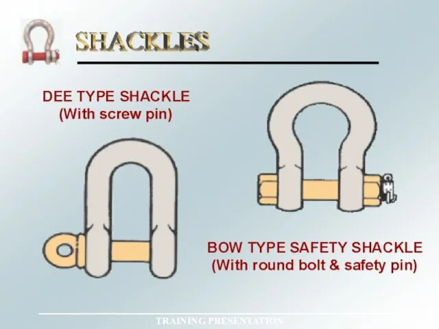
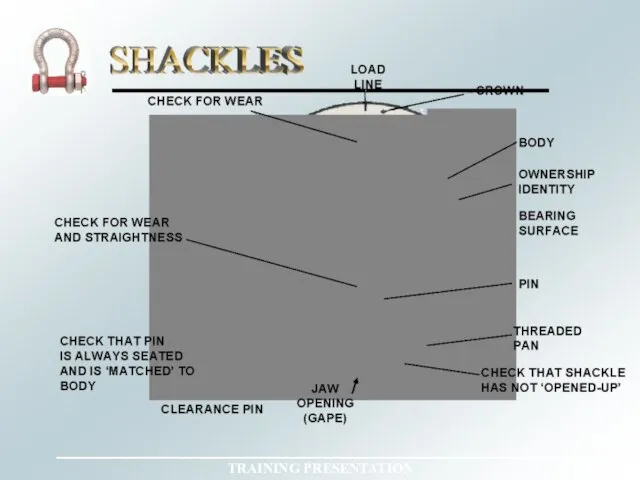
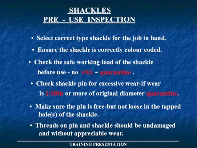
SHACKLES
PRE - USE INSPECTION
Select correct type shackle for
_____________________________________
TRAINING PRESENTATION
SHACKLES
PRE - USE INSPECTION
Select correct type shackle for
Слайд 87_____________________________________
TRAINING PRESENTATION
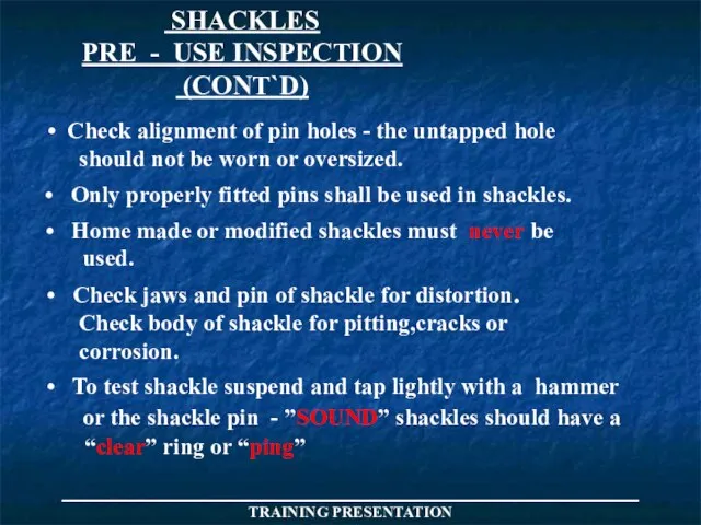
SHACKLES
PRE - USE INSPECTION
(CONT`D)
Check alignment of pin holes
_____________________________________
TRAINING PRESENTATION
SHACKLES
PRE - USE INSPECTION
(CONT`D)
Check alignment of pin holes
Слайд 88_____________________________________
TRAINING PRESENTATION
SAFE WORKING LOADS OF ALLOY SHACKLES
(U.S.FEDERAL SPEC.)
ANCHOR SHACKLE
WITH SCREW PIN
SAFETY
_____________________________________
TRAINING PRESENTATION
SAFE WORKING LOADS OF ALLOY SHACKLES
(U.S.FEDERAL SPEC.)
ANCHOR SHACKLE
WITH SCREW PIN
SAFETY

Слайд 89END
OF
DAY TWO
END
OF
DAY TWO

Слайд 90_____________________________________
TRAINING PRESENTATION
_____________________________________
TRAINING PRESENTATION
Слайд 91_____________________________________
TRAINING PRESENTATION
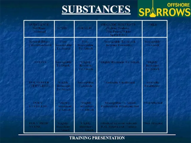
SUBSTANCES
_____________________________________
TRAINING PRESENTATION
SUBSTANCES
Слайд 92_____________________________________
TRAINING PRESENTATION
_____________________________________
TRAINING PRESENTATION
Слайд 93_____________________________________
TRAINING PRESENTATION
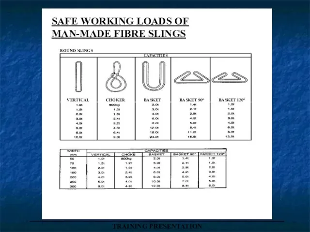
SAFE WORKING LOADS OF
MAN-MADE FIBRE SLINGS
VERTICAL
CHOKER
BASKET
BASKET 90°
BASKET 120°
CAPACITIES
ROUND SLINGS
_____________________________________
TRAINING PRESENTATION
SAFE WORKING LOADS OF
MAN-MADE FIBRE SLINGS
VERTICAL
CHOKER
BASKET
BASKET 90°
BASKET 120°
CAPACITIES
ROUND SLINGS
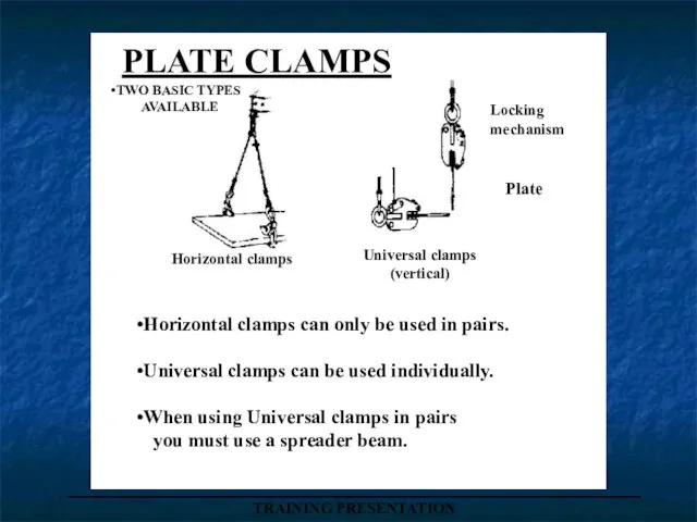
Слайд 94PLATE CLAMPS
TWO BASIC TYPES
AVAILABLE
Horizontal clamps can only be used in pairs.
Universal
PLATE CLAMPS
TWO BASIC TYPES
AVAILABLE
Horizontal clamps can only be used in pairs.
Universal
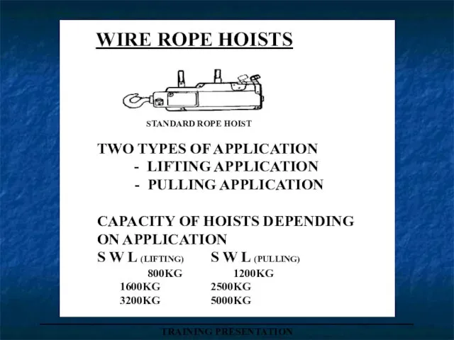
Слайд 95WIRE ROPE HOISTS
STANDARD ROPE HOIST
TWO TYPES OF APPLICATION
- LIFTING APPLICATION
-
WIRE ROPE HOISTS
STANDARD ROPE HOIST
TWO TYPES OF APPLICATION
- LIFTING APPLICATION
-
Слайд 96_____________________________________
TRAINING PRESENTATION
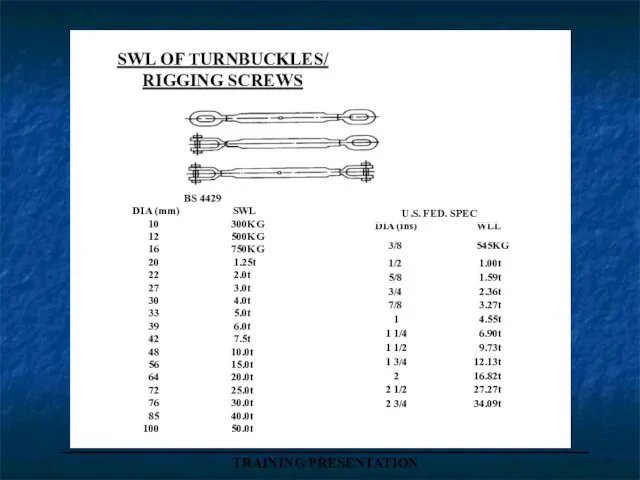
SWL OF TURNBUCKLES/
RIGGING SCREWS
BS 4429
DIA (mm) SWL
10 300KG
_____________________________________
TRAINING PRESENTATION
SWL OF TURNBUCKLES/
RIGGING SCREWS
BS 4429
DIA (mm) SWL
10 300KG
Слайд 97_____________________________________
TRAINING PRESENTATION
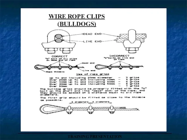
WIRE ROPE CLIPS
(BULLDOGS)
_____________________________________
TRAINING PRESENTATION
WIRE ROPE CLIPS
(BULLDOGS)
Слайд 98_____________________________________
TRAINING PRESENTATION
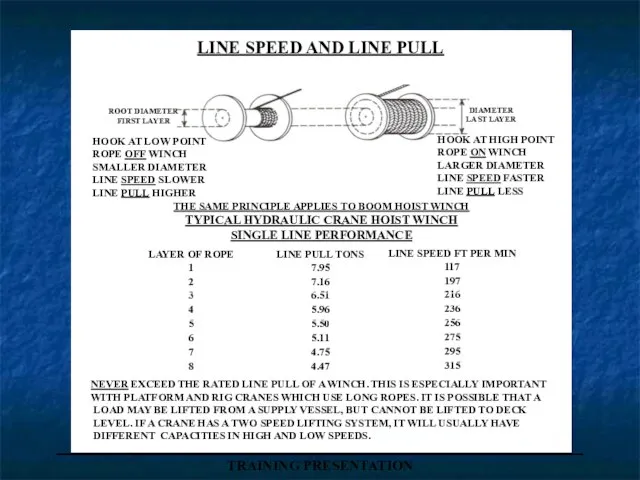
LINE SPEED AND LINE PULL
ROOT DIAMETER
FIRST LAYER
DIAMETER
LAST LAYER
NEVER EXCEED THE RATED
_____________________________________
TRAINING PRESENTATION
LINE SPEED AND LINE PULL
ROOT DIAMETER
FIRST LAYER
DIAMETER
LAST LAYER
NEVER EXCEED THE RATED
Слайд 99_____________________________________
TRAINING PRESENTATION
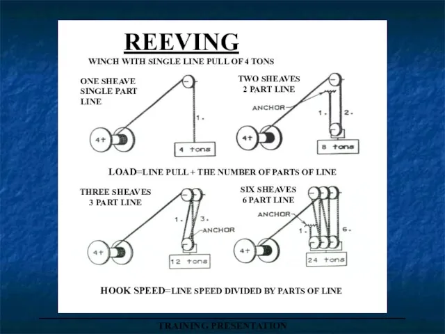
REEVING
WINCH WITH SINGLE LINE PULL OF 4 TONS
ONE SHEAVE
SINGLE PART
LINE
TWO SHEAVES
2
_____________________________________
TRAINING PRESENTATION
REEVING
WINCH WITH SINGLE LINE PULL OF 4 TONS
ONE SHEAVE
SINGLE PART
LINE
TWO SHEAVES
2
Слайд 100_____________________________________
TRAINING PRESENTATION
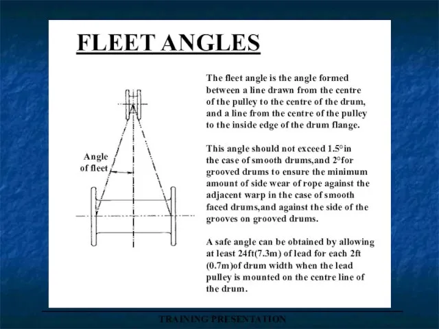
Angle
of fleet
The fleet angle is the angle formed
between a line
_____________________________________
TRAINING PRESENTATION
Angle
of fleet
The fleet angle is the angle formed
between a line
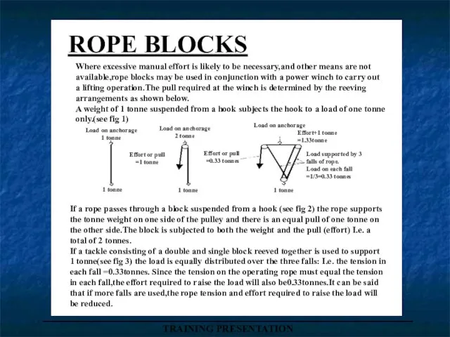
Слайд 101ROPE BLOCKS
_____________________________________
TRAINING PRESENTATION
Load on anchorage
1 tonne
Load on anchorage
2 tonne
Load on anchorage
Effort+1 tonne
=1.33tonne
1
ROPE BLOCKS
_____________________________________
TRAINING PRESENTATION
Load on anchorage
1 tonne
Load on anchorage
2 tonne
Load on anchorage
Effort+1 tonne
=1.33tonne
1
Слайд 102_____________________________________
TRAINING PRESENTATION
ROPE BLOCKS
CONT`D
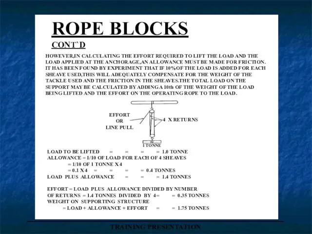
HOWEVER,IN CALCULATING THE EFFORT REQUIRED TO LIFT THE LOAD
_____________________________________
TRAINING PRESENTATION
ROPE BLOCKS
CONT`D
HOWEVER,IN CALCULATING THE EFFORT REQUIRED TO LIFT THE LOAD
Слайд 103TABLE LOADINGS
ARRANGEMENT
SINGLE
2 SINGLE
DOUBLE AND
SINGLE
2 DOUBLE
2 TREBLE
DOUBLE AND
TREBLE
THE FIGURE AGAINST
THE BLOCK INDICATES
THE NUMBER
TABLE LOADINGS
ARRANGEMENT
SINGLE
2 SINGLE
DOUBLE AND
SINGLE
2 DOUBLE
2 TREBLE
DOUBLE AND
TREBLE
THE FIGURE AGAINST
THE BLOCK INDICATES
THE NUMBER
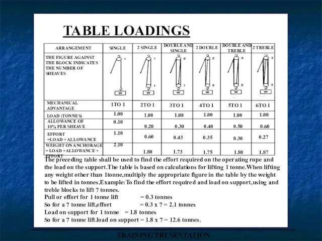
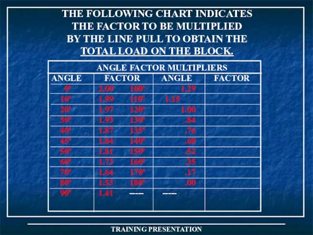
Слайд 104THE FOLLOWING CHART INDICATES
THE FACTOR TO BE MULTIPLIED
BY THE LINE PULL TO
THE FOLLOWING CHART INDICATES
THE FACTOR TO BE MULTIPLIED
BY THE LINE PULL TO
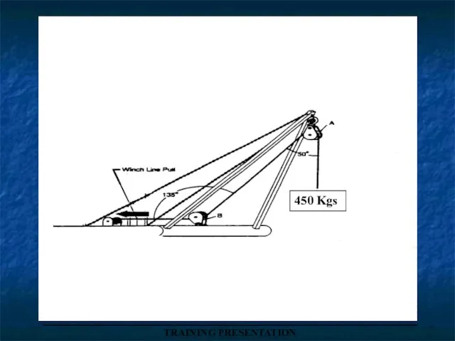
Слайд 105450 Kgs
_____________________________________
TRAINING PRESENTATION
450 Kgs
_____________________________________
TRAINING PRESENTATION
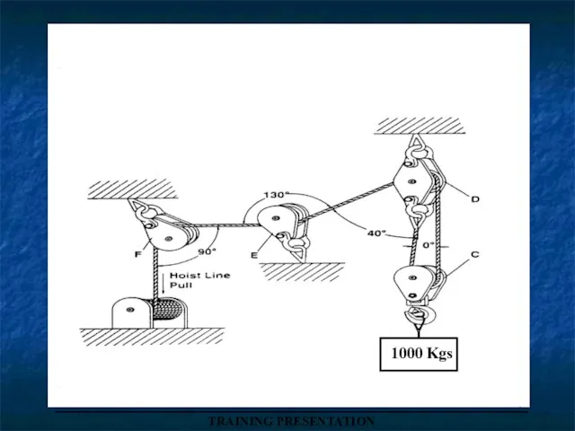
Слайд 106_____________________________________
TRAINING PRESENTATION
1000 Kgs
_____________________________________
TRAINING PRESENTATION
1000 Kgs
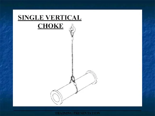
Слайд 107SINGLE VERTICAL
CHOKE
_____________________________________
TRAINING PRESENTATION
SINGLE VERTICAL
CHOKE
_____________________________________
TRAINING PRESENTATION
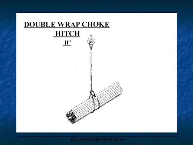
Слайд 108DOUBLE WRAP CHOKE
HITCH
0º
_____________________________________
TRAINING PRESENTATION
DOUBLE WRAP CHOKE
HITCH
0º
_____________________________________
TRAINING PRESENTATION
Слайд 109_____________________________________
TRAINING PRESENTATION
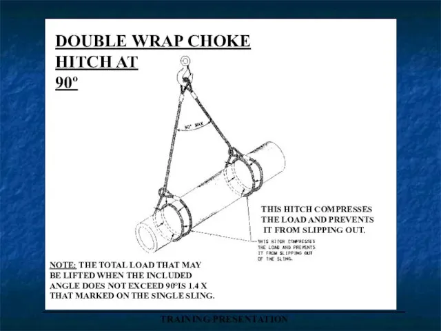
DOUBLE WRAP CHOKE
HITCH AT
90º
THIS HITCH COMPRESSES
THE LOAD AND PREVENTS
_____________________________________
TRAINING PRESENTATION
DOUBLE WRAP CHOKE
HITCH AT
90º
THIS HITCH COMPRESSES
THE LOAD AND PREVENTS
Слайд 110_____________________________________
TRAINING PRESENTATION
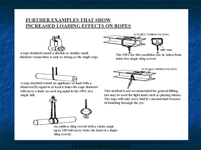
FURTHER EXAMPLES THAT SHOW
INCREASED LOADING EFFECTS ON ROPES
SUITABLE TIMBER PACKING
SUITABLE TIMBER
_____________________________________
TRAINING PRESENTATION
FURTHER EXAMPLES THAT SHOW
INCREASED LOADING EFFECTS ON ROPES
SUITABLE TIMBER PACKING
SUITABLE TIMBER
Слайд 112_____________________________________
TRAINING PRESENTATION
_____________________________________
TRAINING PRESENTATION
Слайд 113______________________________________________________________
TRAINING PRESENTATION
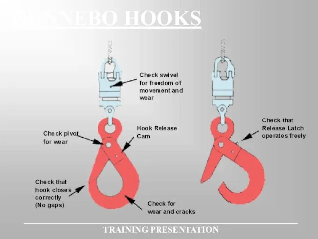
GUNNEBO HOOKS
______________________________________________________________
TRAINING PRESENTATION
GUNNEBO HOOKS
Слайд 114_____________________________________
TRAINING PRESENTATION
RIGHT AND WRONG PULLEY GROOVES
WRONG
PULLEY GROOVE
TOO NARROW
WRONG
PULLEY GROOVE
TOO WIDE
RIGHT
PULLEY GROOVE
CORRECT.
120º OR
_____________________________________
TRAINING PRESENTATION
RIGHT AND WRONG PULLEY GROOVES
WRONG
PULLEY GROOVE
TOO NARROW
WRONG
PULLEY GROOVE
TOO WIDE
RIGHT
PULLEY GROOVE
CORRECT.
120º OR

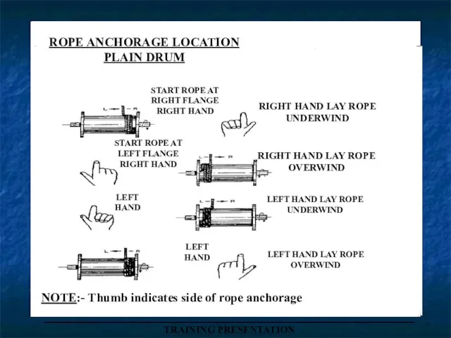
Слайд 115ROPE ANCHORAGE LOCATION
PLAIN DRUM
START ROPE AT
RIGHT FLANGE
RIGHT HAND
RIGHT HAND LAY ROPE
UNDERWIND
START
ROPE ANCHORAGE LOCATION
PLAIN DRUM
START ROPE AT
RIGHT FLANGE
RIGHT HAND
RIGHT HAND LAY ROPE
UNDERWIND
START
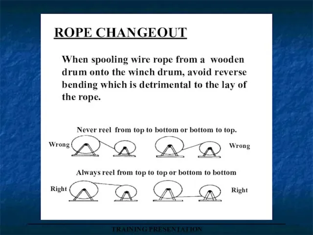
Слайд 116When spooling wire rope from a wooden
drum onto the winch drum,
When spooling wire rope from a wooden
drum onto the winch drum,
Слайд 117_____________________________________
TRAINING PRESENTATION
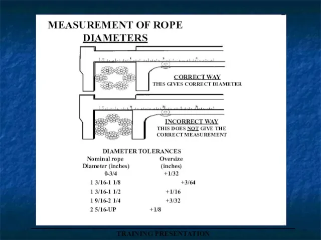
MEASUREMENT OF ROPE
DIAMETERS
CORRECT WAY
THIS GIVES CORRECT DIAMETER
INCORRECT WAY
THIS DOES NOT GIVE
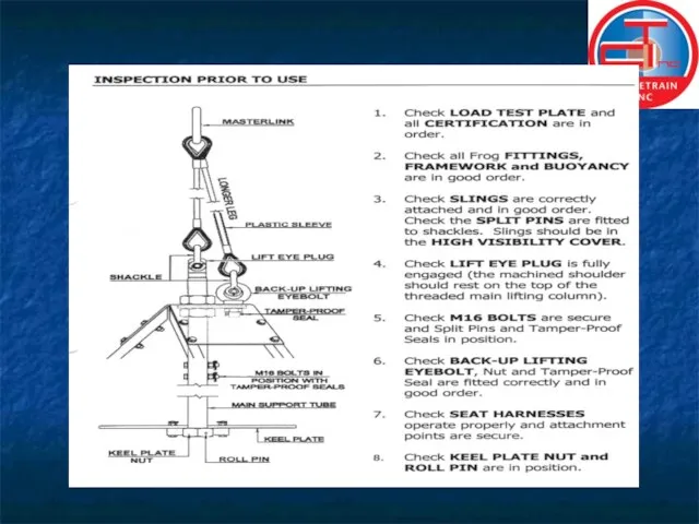
_____________________________________
TRAINING PRESENTATION
MEASUREMENT OF ROPE
DIAMETERS
CORRECT WAY
THIS GIVES CORRECT DIAMETER
INCORRECT WAY
THIS DOES NOT GIVE
Слайд 118_____________________________________
TRAINING PRESENTATION
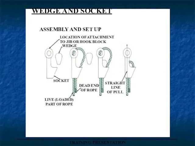
LOCATION OF ATTACHMENT
TO JIB OR HOOK BLOCK
WEDGE
SOCKET
DEAD END
OF ROPE
STRAIGHT
LINE
OF
_____________________________________
TRAINING PRESENTATION
LOCATION OF ATTACHMENT
TO JIB OR HOOK BLOCK
WEDGE
SOCKET
DEAD END
OF ROPE
STRAIGHT
LINE
OF
Слайд 119_____________________________________
TRAINING PRESENTATION
RECOMMENDED ROPE
TERMINATION
TO BS 7166
THE DEAD END IS LOOPED
BACK ON ITSELF &
_____________________________________
TRAINING PRESENTATION
RECOMMENDED ROPE
TERMINATION
TO BS 7166
THE DEAD END IS LOOPED
BACK ON ITSELF &
Слайд 120_____________________________________
TRAINING PRESENTATION
_____________________________________
TRAINING PRESENTATION
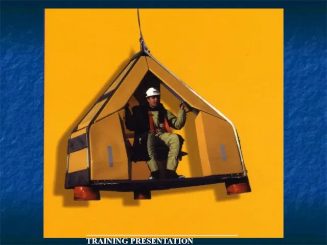
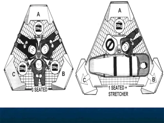
Слайд 121OPERATIONAL ENVELOPE
The FROG has been designed to ensure passengers safely even when
OPERATIONAL ENVELOPE
The FROG has been designed to ensure passengers safely even when

Слайд 122TRANSFER LOG
As for most potentially hazardous operations carried out in the offshore
TRANSFER LOG
As for most potentially hazardous operations carried out in the offshore

Слайд 123FROG OPERATING INSTRUCTIONS
PRE‑TRANSFER
1. Supervisor ‑ Conduct Pre‑transfer hazard analysis
: Conduct Inspection
FROG OPERATING INSTRUCTIONS
PRE‑TRANSFER
1. Supervisor ‑ Conduct Pre‑transfer hazard analysis
: Conduct Inspection
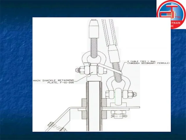
Слайд 124 LIFT‑OFF
Deck Crew ‑ Hook‑up Master link and Safety Loop
2. Deck Crew
LIFT‑OFF
Deck Crew ‑ Hook‑up Master link and Safety Loop
2. Deck Crew
Слайд 125 LANDING
1. Crane Op. ‑ All raising and lowering must be over
LANDING
1. Crane Op. ‑ All raising and lowering must be over

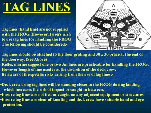
Слайд 127TAG LINES
Tag lines (hand line) are not supplied
with the FROG. However
TAG LINES
Tag lines (hand line) are not supplied
with the FROG. However
Слайд 130APPROVED
PERSONNEL
NETS
_____________________________________
TRAINING PRESENTATION
(Billy Pugh)
APPROVED
PERSONNEL
NETS
_____________________________________
TRAINING PRESENTATION
(Billy Pugh)
Слайд 131ARE THERE ANY QUESTIONS?
ARE THERE ANY QUESTIONS?

 Išmokite veiksmažodžius
 Состав Общественной Палаты города Хабаровска
 Урок здоровья
 Типология политических режимов
 Предложения ARQA Technologies для брокеров Владимир Курляндчик Директор по развитию, ARQA Technologies
 Кухни народов Кавказа
 Теория и методика физического воспитания как учебная дисциплина, ее основные понятия. Лекция 1
 Характер как свойство личности
 Презентация спортивных мероприятий Гимназии №1582 за 2011год
 Конкурсы проекта Profesarium
 Единицы силы
 Ответственность за нарушение валютного законодательства Российской Федерации и актов органов валютного регулирования
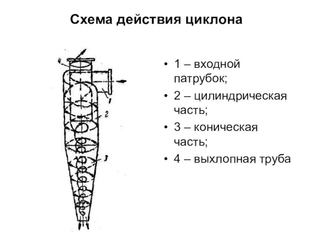 Схема действия циклона
  История семи великих камней Алмазного фонда России
 Презентация на тему Жан-Батист Мольер
  ИП
ИП Презентация на тему Вредные привычки: курение и алкоголь
 Портрет работы И. Е. Репина
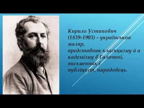 Західноукраїнські художники
 Глаза боятся, а руки делают!Развитие проекта мониторинга рекламы
 Опыт использования технологии блокчейн на российском рынке нефтепродуктов
 System Life Cycle Systems Development
 Возрождение - эпоха в истории культуры Европы, пришедшая на смену средним векам и предшествующая просвещению
 Презентация на тему Внеклассное мероприятие по правилам дорожного движения
  Музыка осени
 «Уравнения. Решение задач с помощью уравнений ».
 11 Ноября
 Презентация на тему Наши предки - славян