- Workshop 8.3 3D Pipe Junction O-grid

Содержание
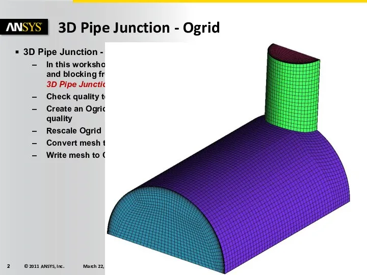
- 2. 3D Pipe Junction - Ogrid 3D Pipe Junction - Ogrid In this workshop, we will open
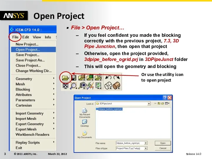
- 3. Open Project File > Open Project… If you feel confident you made the blocking correctly with
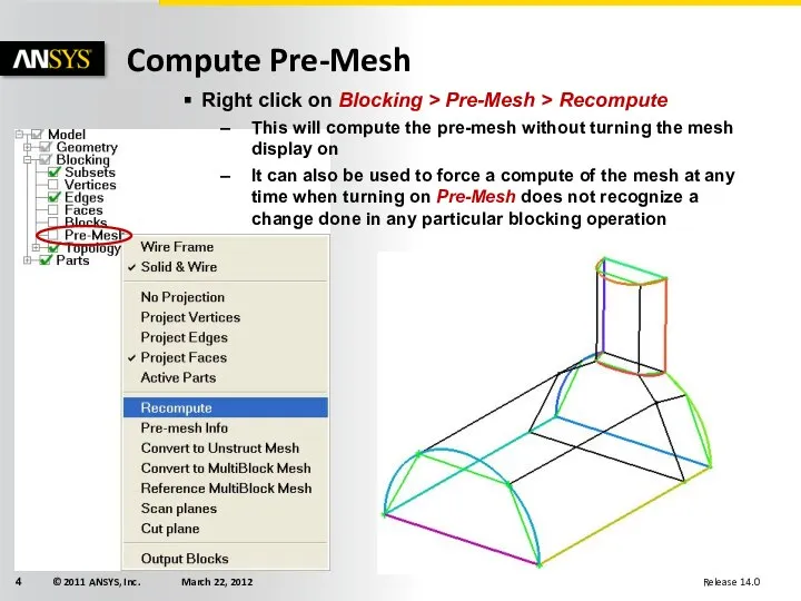
- 4. Compute Pre-Mesh Right click on Blocking > Pre-Mesh > Recompute This will compute the pre-mesh without
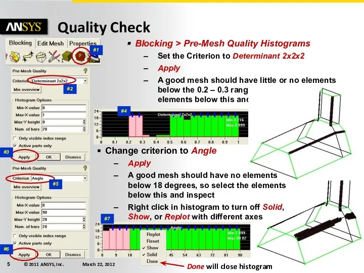
- 5. #2 #1 Quality Check Blocking > Pre-Mesh Quality Histograms Set the Criterion to Determinant 2x2x2 Apply
- 6. Surface Mesh Display The problem mesh is easily seen by looking at just the surface mesh
- 7. Create Ogrid First, turn ON Edges and all parts (except VORFN), and turn OFF Pre-Mesh Blocking
- 8. Rescale Ogrid Rescaling Ogrid is one of the commands that can work on only visible vertices
- 9. Update Sizes Any new edges have 2 nodes by default Blocking > Pre-Mesh Params > Update
- 10. Set Edge Parameters for Boundary Layer Blocking > Pre-Mesh Params > Edge Params Do NOT Update
- 11. Recheck Quality Check determinant and angle again Blocking > Pre-mesh Quality Histograms Check Determinant 2x2x2 then
- 12. Move Vertex Blocking > Move Vertex > Move Vertex With the Method set to Single, press
- 13. Quality compare Initial Determinant Improved Determinant Initial Angle Improved Angle After Ogrid Creation Before Ogrid Creation
- 15. Скачать презентацию
Слайд 3Open Project
File > Open Project…
If you feel confident you made the
Open Project
File > Open Project…
If you feel confident you made the
Слайд 4Compute Pre-Mesh
Right click on Blocking > Pre-Mesh > Recompute
This will compute the
Compute Pre-Mesh
Right click on Blocking > Pre-Mesh > Recompute
This will compute the
Слайд 5#2
#1
Quality Check
Blocking > Pre-Mesh Quality Histograms
Set the Criterion to Determinant 2x2x2
Apply
A
#2
#1
Quality Check
Blocking > Pre-Mesh Quality Histograms
Set the Criterion to Determinant 2x2x2
Apply
A
Слайд 6Surface Mesh Display
The problem mesh is easily seen by looking at just
Surface Mesh Display
The problem mesh is easily seen by looking at just
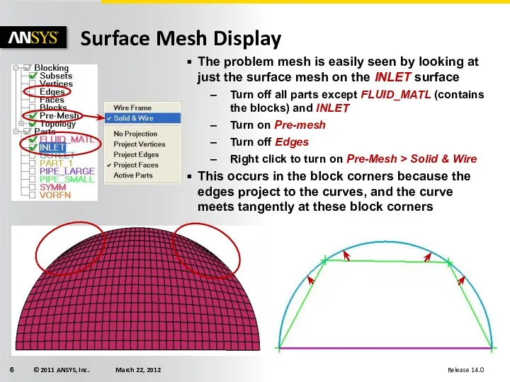
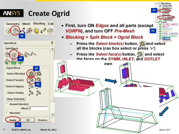
Слайд 7Create Ogrid
First, turn ON Edges and all parts (except VORFN), and turn
Create Ogrid
First, turn ON Edges and all parts (except VORFN), and turn
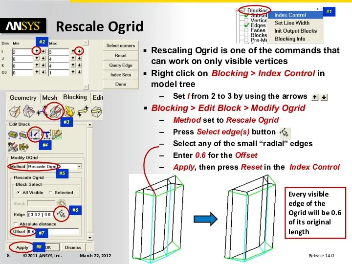
Слайд 8Rescale Ogrid
Rescaling Ogrid is one of the commands that can work on
Rescale Ogrid
Rescaling Ogrid is one of the commands that can work on
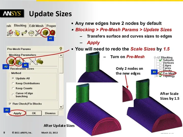
Слайд 9Update Sizes
Any new edges have 2 nodes by default
Blocking > Pre-Mesh Params
Update Sizes
Any new edges have 2 nodes by default
Blocking > Pre-Mesh Params
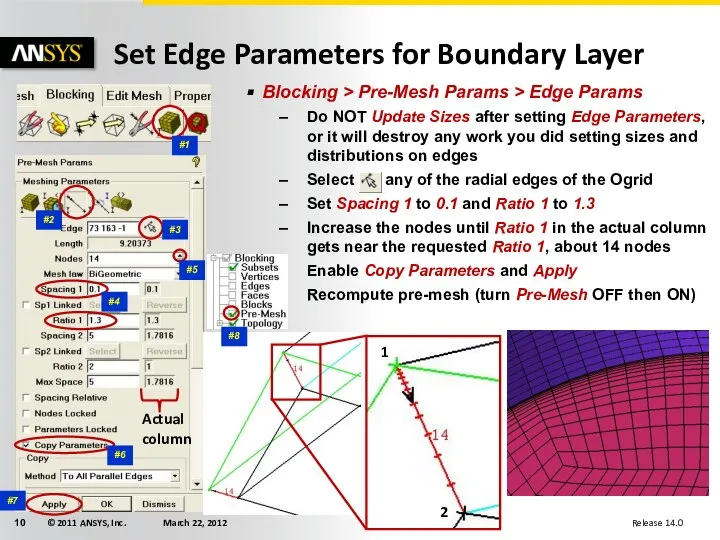
Слайд 10Set Edge Parameters for Boundary Layer
Blocking > Pre-Mesh Params > Edge Params
Do
Set Edge Parameters for Boundary Layer
Blocking > Pre-Mesh Params > Edge Params
Do
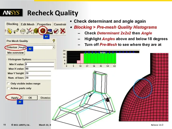
Слайд 11Recheck Quality
Check determinant and angle again
Blocking > Pre-mesh Quality Histograms
Check Determinant 2x2x2
Recheck Quality
Check determinant and angle again
Blocking > Pre-mesh Quality Histograms
Check Determinant 2x2x2
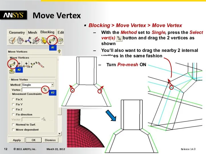
Слайд 12Move Vertex
Blocking > Move Vertex > Move Vertex
With the Method set to
Move Vertex
Blocking > Move Vertex > Move Vertex
With the Method set to
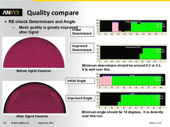
Слайд 13Quality compare
Initial Determinant
Improved Determinant
Initial Angle
Improved Angle
After Ogrid Creation
Before Ogrid Creation
RE-check Determinant and
Quality compare
Initial Determinant
Improved Determinant
Initial Angle
Improved Angle
After Ogrid Creation
Before Ogrid Creation
RE-check Determinant and
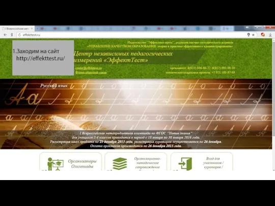 Регистрация на сайте независимых педагогических измерений Эффект Тест
 Представление информации в компьютере
 L_6_2
L_6_2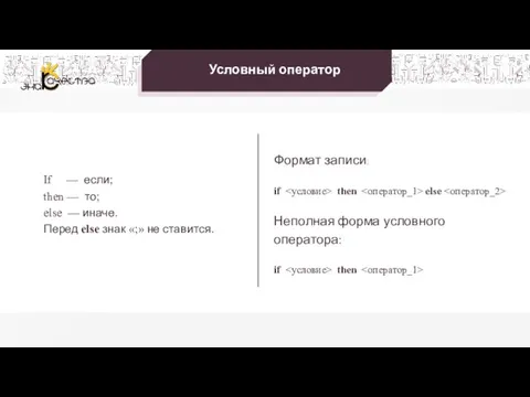 Программирование разветвляющихся алгоритмов
 Трон — многопользовательская аркадная игра, основанная на одноименном фильме 1982 года
 QR - коды для игр
 Памяти поколений. Дни воинской славы России! Создание документации с помощью электронных таблиц
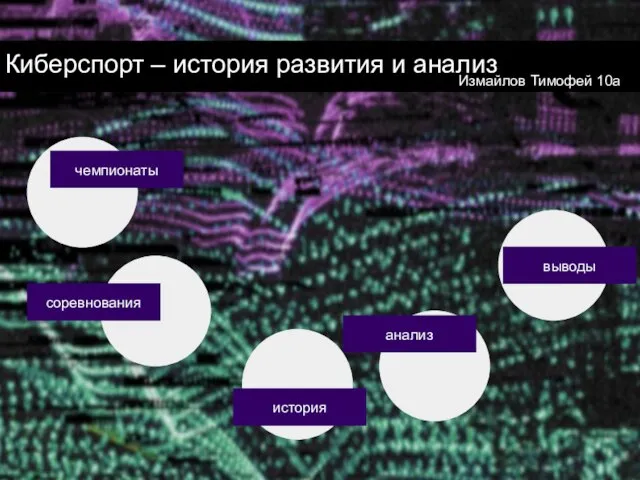 Киберспорт – история развития и анализ
 7-1-6
7-1-6 Поиск информации в интернете. Описание мертвого моря на основе материалов интернета
 Презентация на тему Вычислительная техника четвертого поколения
 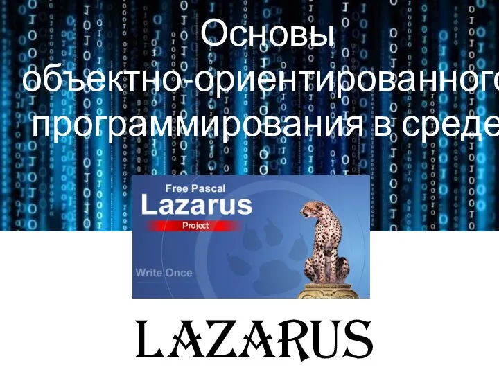 События объекта TForm. Управление с клавиатуры. Lazarus. Урок 16
 Анализ рынка по PAM-TAM-SAM-SOM. Приложение Map Sport, команда Турник-мены
 Бережливое производство. Система 5 С. Как организовать рабочее место
 Теория медиа (медиапродукт)
 Презентация на тему ОС Windows. История её развития и применение
  Выходные графические примитивы
 Батут-арена
 Технологии Smart, KPI, TO
 Application Stepsfor Students
 Зачем мне нужен личный блог?
 Microsoft Excel. Основы работы с программой
 Как сохранить сертификат участника в онлайн-викторине Моя Родина - Россия
 Использование ГИС-технологий для функционально-экологической оценки лесов
 Web – конструирование на HTML
 Безопасность жизнедеятельности. Дистанционное обучение
 Курсы по Blender в skullbox
 Проекты Медиагруппы