- CONTROL OF SEAKEEPING Theory

Содержание
- 2. CONTROL OF SEAKEEPING Main seakeeping qualities: Floatability Stability Damage trim and stability (floodability) Ship’s strength Ship
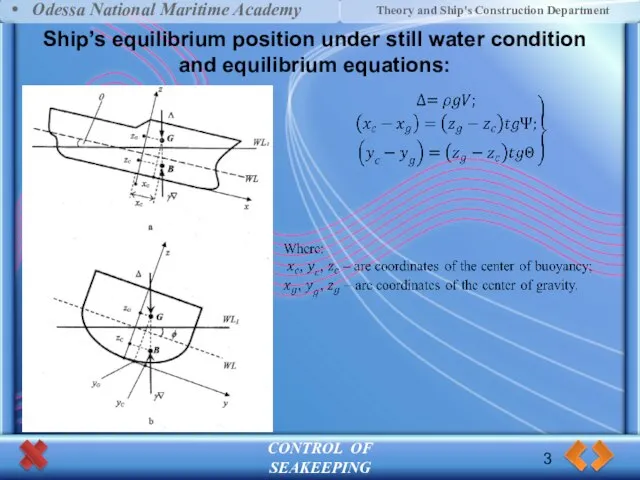
- 3. CONTROL OF SEAKEEPING Ship’s equilibrium position under still water condition and equilibrium equations: 3 Odessa National
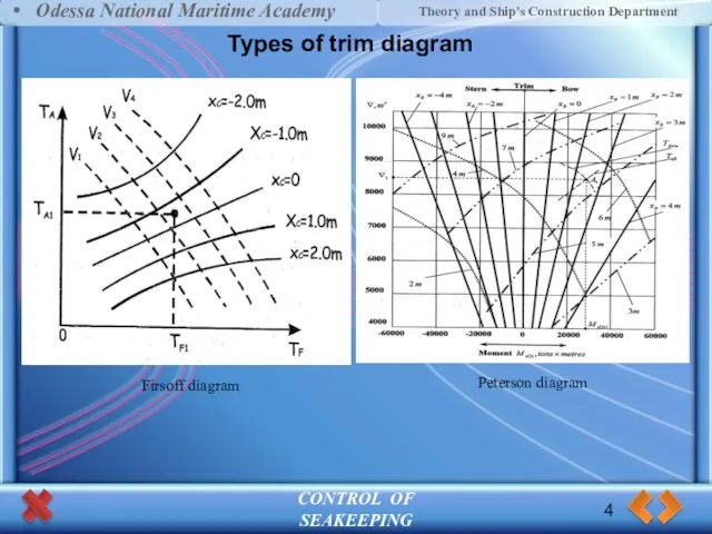
- 4. CONTROL OF SEAKEEPING Types of trim diagram 4 Odessa National Maritime Academy Theory and Ship's Construction
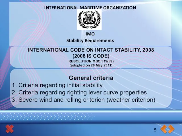
- 5. INTERNATIONAL MARITIME ORGANIZATION IMO Stability Requirements INTERNATIONAL CODE ON INTACT STABILITY, 2008 (2008 IS CODE) RESOLUTION
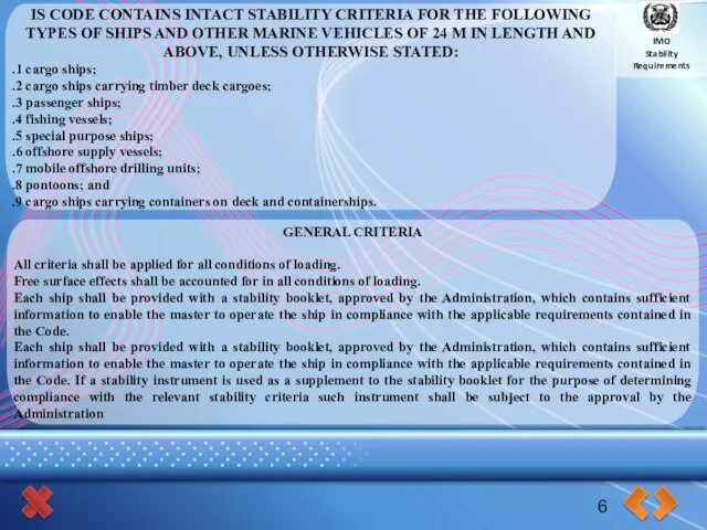
- 6. IMO Stability Requirements IS CODE CONTAINS INTACT STABILITY CRITERIA FOR THE FOLLOWING TYPES OF SHIPS AND
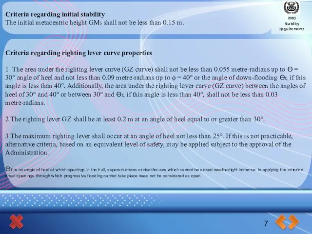
- 7. IMO Stability Requirements Criteria regarding initial stability The initial metacentric height GM0 shall not be less
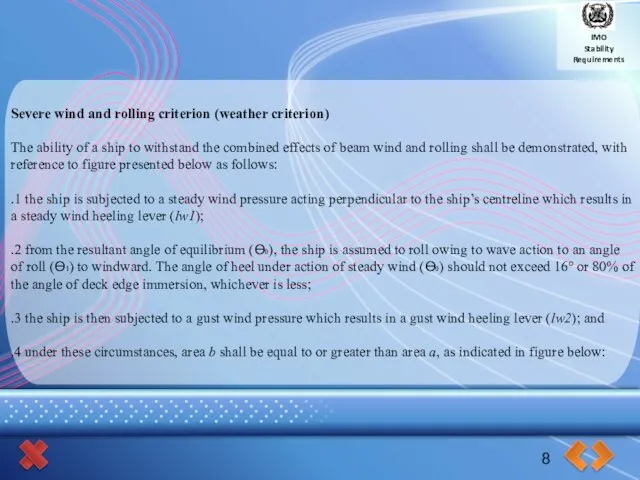
- 8. IMO Stability Requirements 8 Severe wind and rolling criterion (weather criterion) The ability of a ship
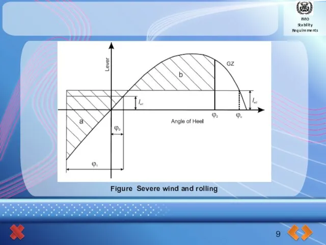
- 9. IMO Stability Requirements 9 Figure Severe wind and rolling
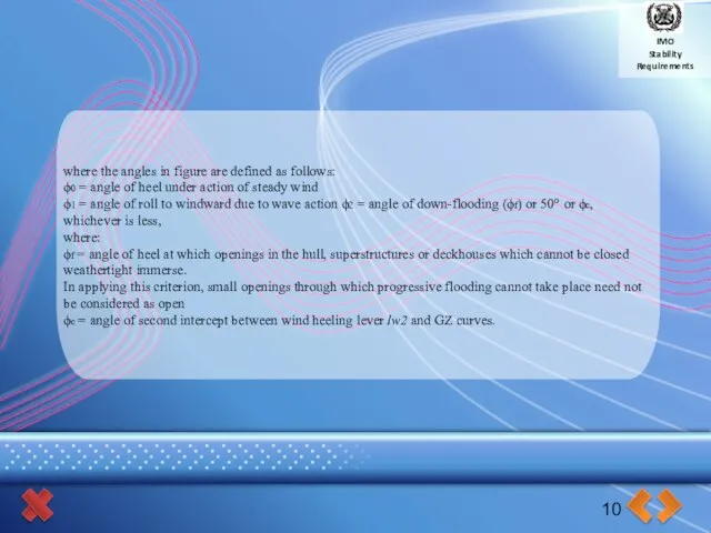
- 10. IMO Stability Requirements 10 where the angles in figure are defined as follows: ϕ0 = angle
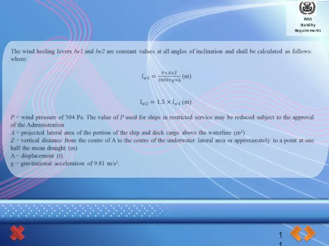
- 11. IMO Stability Requirements 11
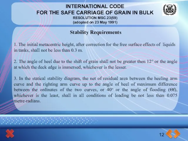
- 12. INTERNATIONAL CODE FOR THE SAFE CARRIAGE OF GRAIN IN BULK RESOLUTION MSC.23(59) (adopted on 23 May
- 13. INTERNATIONAL CODE FOR THE SAFE CARRIAGE OF GRAIN IN BULK RESOLUTION MSC.23(59) (adopted on 23 May
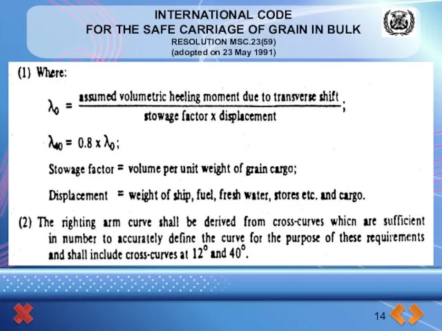
- 14. INTERNATIONAL CODE FOR THE SAFE CARRIAGE OF GRAIN IN BULK RESOLUTION MSC.23(59) (adopted on 23 May
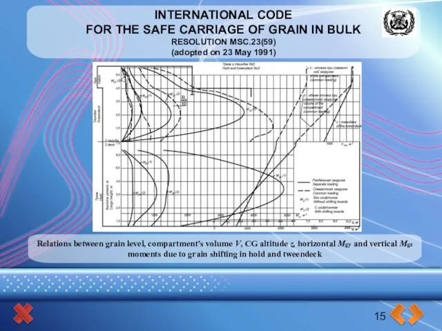
- 15. INTERNATIONAL CODE FOR THE SAFE CARRIAGE OF GRAIN IN BULK RESOLUTION MSC.23(59) (adopted on 23 May
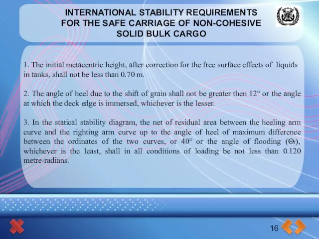
- 16. INTERNATIONAL STABILITY REQUIREMENTS FOR THE SAFE CARRIAGE OF NON-COHESIVE SOLID BULK CARGO 16 1. The initial
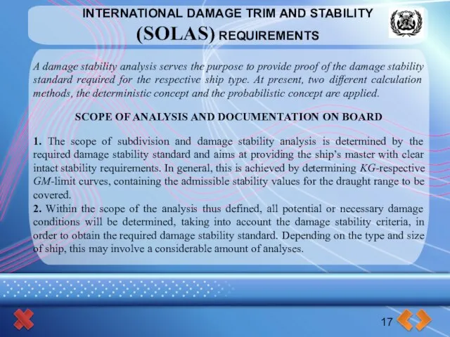
- 17. INTERNATIONAL DAMAGE TRIM AND STABILITY (SOLAS) REQUIREMENTS 17 A damage stability analysis serves the purpose to
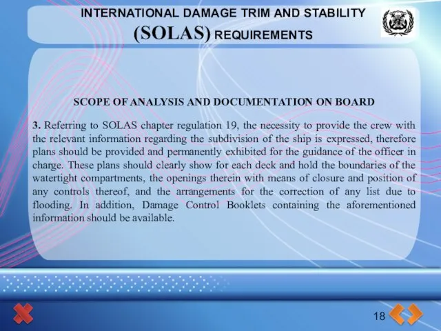
- 18. INTERNATIONAL DAMAGE TRIM AND STABILITY (SOLAS) REQUIREMENTS 18 SCOPE OF ANALYSIS AND DOCUMENTATION ON BOARD 3.
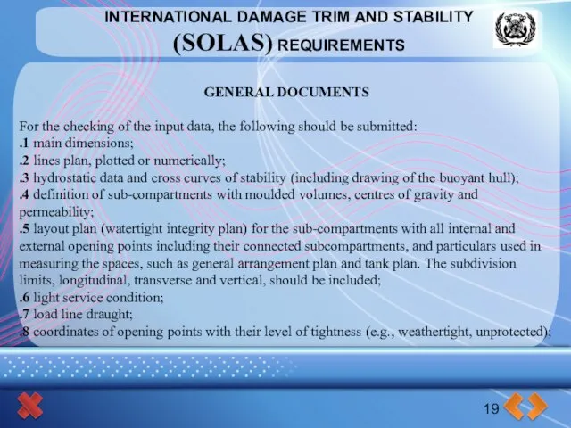
- 19. INTERNATIONAL DAMAGE TRIM AND STABILITY (SOLAS) REQUIREMENTS 19 GENERAL DOCUMENTS For the checking of the input
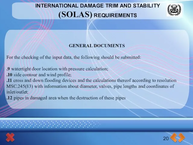
- 20. INTERNATIONAL DAMAGE TRIM AND STABILITY (SOLAS) REQUIREMENTS 20 GENERAL DOCUMENTS For the checking of the input
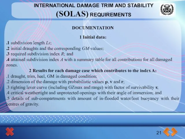
- 21. INTERNATIONAL DAMAGE TRIM AND STABILITY (SOLAS) REQUIREMENTS 21 DOCUMENTATION 1 Initial data: .1 subdivision length Ls;
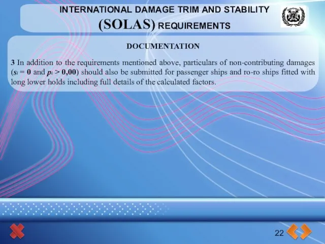
- 22. INTERNATIONAL DAMAGE TRIM AND STABILITY (SOLAS) REQUIREMENTS 22 DOCUMENTATION 3 In addition to the requirements mentioned
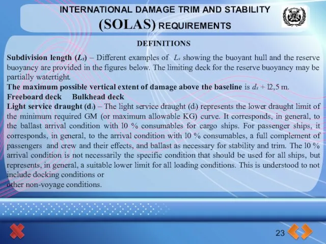
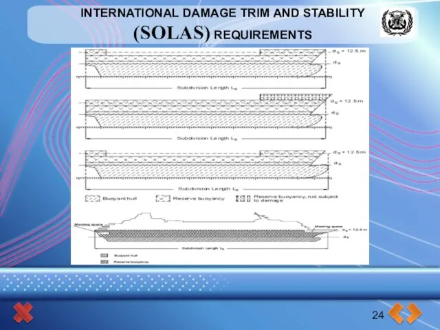
- 23. INTERNATIONAL DAMAGE TRIM AND STABILITY (SOLAS) REQUIREMENTS 23 DEFINITIONS Subdivision length (Ls) – Different examples of
- 24. INTERNATIONAL DAMAGE TRIM AND STABILITY (SOLAS) REQUIREMENTS 24
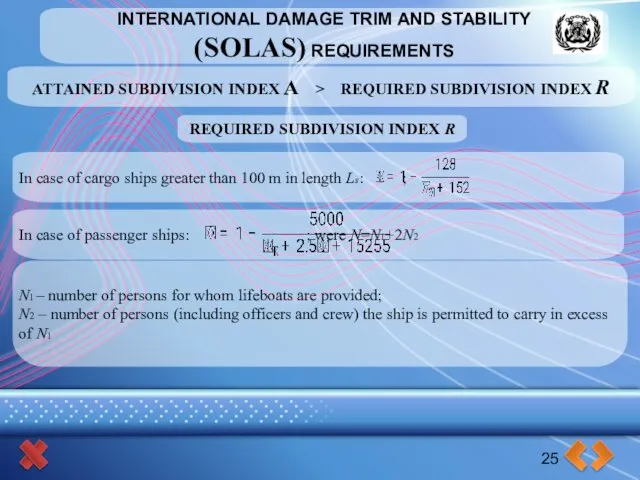
- 25. INTERNATIONAL DAMAGE TRIM AND STABILITY (SOLAS) REQUIREMENTS 25 ATTAINED SUBDIVISION INDEX A > REQUIRED SUBDIVISION INDEX
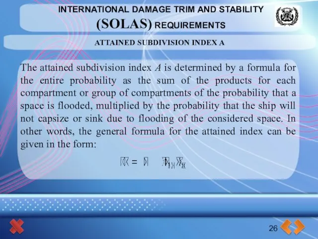
- 26. INTERNATIONAL DAMAGE TRIM AND STABILITY (SOLAS) REQUIREMENTS 26 ATTAINED SUBDIVISION INDEX A The attained subdivision index
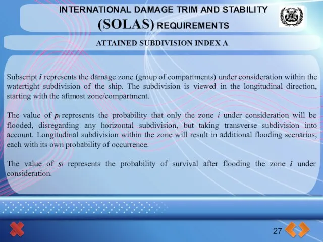
- 27. INTERNATIONAL DAMAGE TRIM AND STABILITY (SOLAS) REQUIREMENTS 27 ATTAINED SUBDIVISION INDEX A Subscript i represents the
- 28. INTERNATIONAL DAMAGE TRIM AND STABILITY (SOLAS) REQUIREMENTS 28
- 29. INTERNATIONAL DAMAGE TRIM AND STABILITY (SOLAS) REQUIREMENTS 29
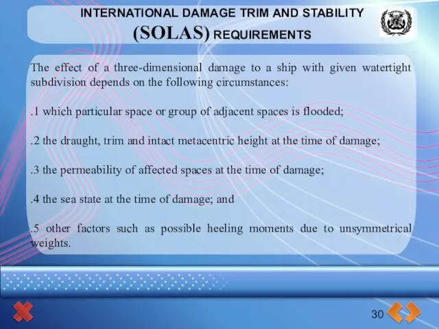
- 30. INTERNATIONAL DAMAGE TRIM AND STABILITY (SOLAS) REQUIREMENTS 30 The effect of a three-dimensional damage to a
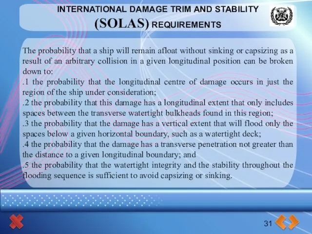
- 31. INTERNATIONAL DAMAGE TRIM AND STABILITY (SOLAS) REQUIREMENTS 31 The probability that a ship will remain afloat
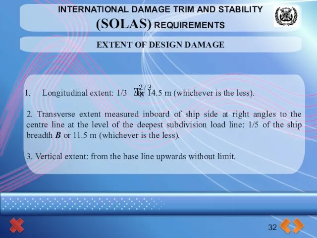
- 32. INTERNATIONAL DAMAGE TRIM AND STABILITY (SOLAS) REQUIREMENTS 32 EXTENT OF DESIGN DAMAGE Longitudinal extent: 1/3 or
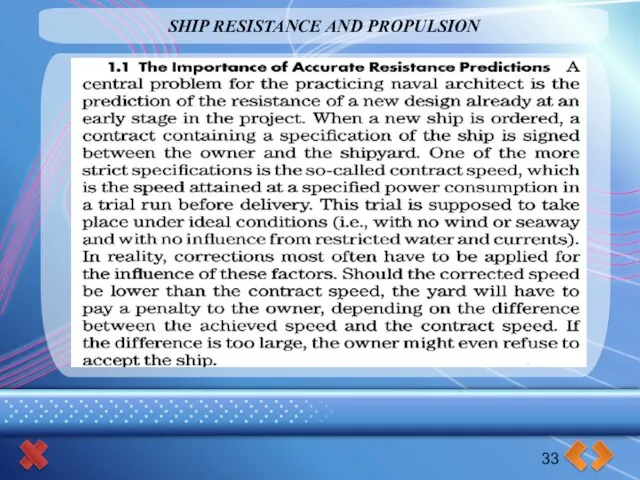
- 33. SHIP RESISTANCE AND PROPULSION 33
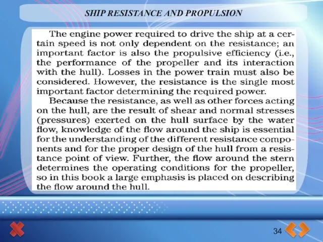
- 34. SHIP RESISTANCE AND PROPULSION 34
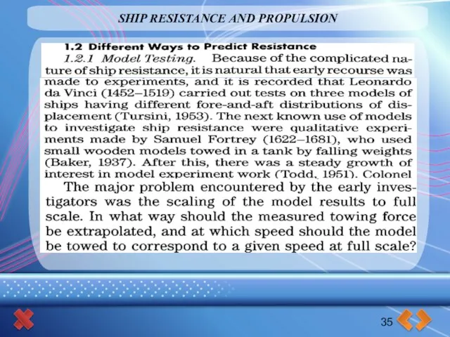
- 35. SHIP RESISTANCE AND PROPULSION 35
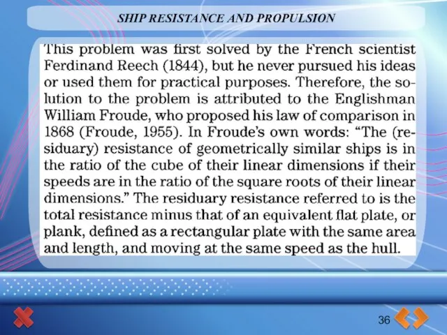
- 36. SHIP RESISTANCE AND PROPULSION 36
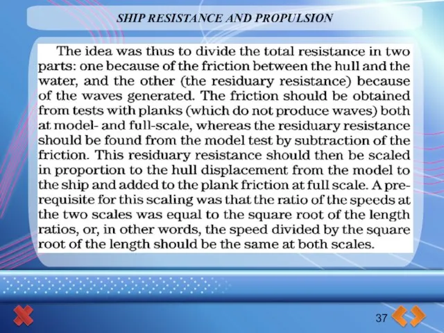
- 37. SHIP RESISTANCE AND PROPULSION 37
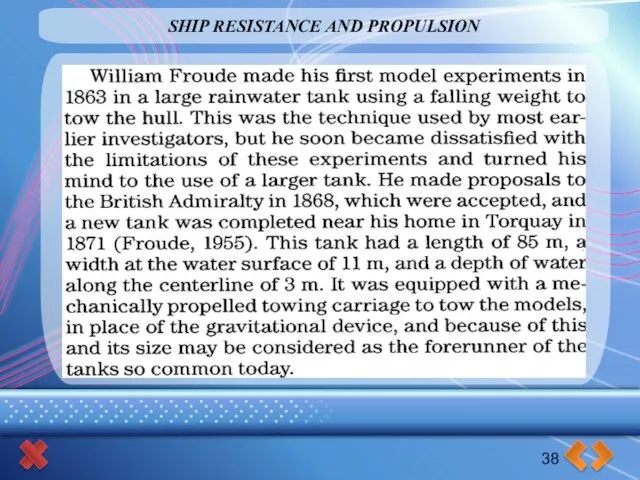
- 38. SHIP RESISTANCE AND PROPULSION 38
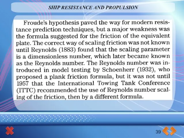
- 39. SHIP RESISTANCE AND PROPULSION 39
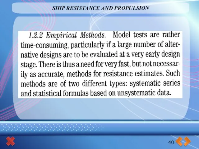
- 40. SHIP RESISTANCE AND PROPULSION 40
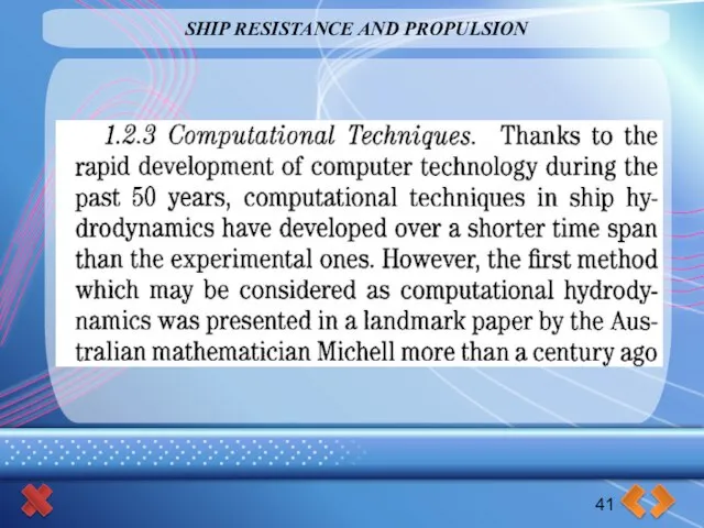
- 41. SHIP RESISTANCE AND PROPULSION 41
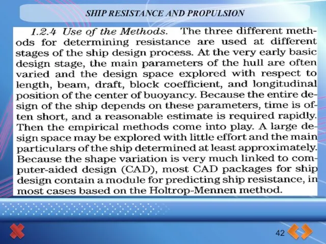
- 42. SHIP RESISTANCE AND PROPULSION 42
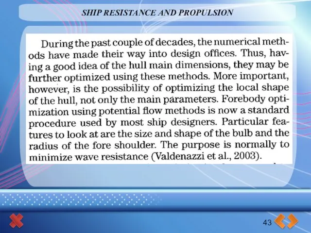
- 43. SHIP RESISTANCE AND PROPULSION 43
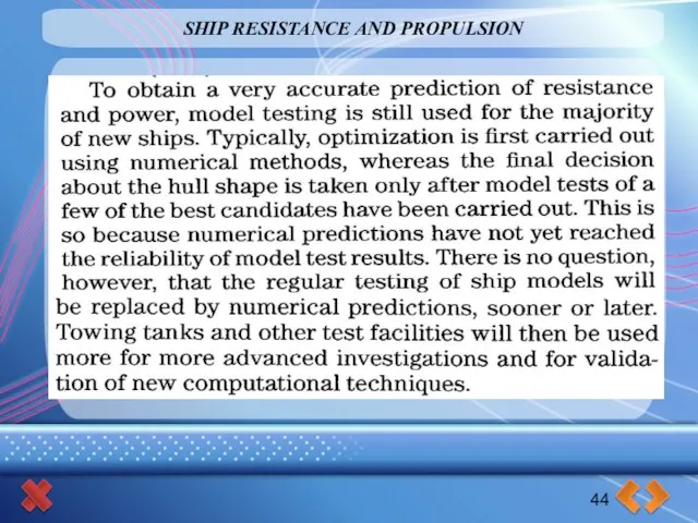
- 44. SHIP RESISTANCE AND PROPULSION 44
- 45. SHIP RESISTANCE AND PROPULSION 45
- 46. SHIP RESISTANCE AND PROPULSION 46
- 47. SHIP RESISTANCE AND PROPULSION 46
- 48. SHIP RESISTANCE AND PROPULSION 46
- 49. STRENGTH OF SHIPS 32 SPECIFIC FEATURES OF SHIP STRUCTURES 1. Nature of Ship Structures 2. Size
- 51. Скачать презентацию
Слайд 2CONTROL OF
SEAKEEPING
Main seakeeping qualities:
Floatability
Stability
Damage trim and stability (floodability)
Ship’s strength
Ship resistance
Ship propulsion
Ship
CONTROL OF
SEAKEEPING
Main seakeeping qualities:
Floatability
Stability
Damage trim and stability (floodability)
Ship’s strength
Ship resistance
Ship propulsion
Ship
Слайд 3CONTROL OF
SEAKEEPING
Ship’s equilibrium position under still water condition
and equilibrium equations:
3
Odessa National Maritime
CONTROL OF
SEAKEEPING
Ship’s equilibrium position under still water condition
and equilibrium equations:
3
Odessa National Maritime
Слайд 4CONTROL OF
SEAKEEPING
Types of trim diagram
4
Odessa National Maritime Academy
Theory and Ship's Construction
CONTROL OF
SEAKEEPING
Types of trim diagram
4
Odessa National Maritime Academy
Theory and Ship's Construction
Слайд 5INTERNATIONAL MARITIME ORGANIZATION
IMO
Stability Requirements
INTERNATIONAL CODE ON INTACT STABILITY, 2008
(2008 IS CODE)
RESOLUTION MSC.319(89)
(adopted
INTERNATIONAL MARITIME ORGANIZATION
IMO
Stability Requirements
INTERNATIONAL CODE ON INTACT STABILITY, 2008
(2008 IS CODE)
RESOLUTION MSC.319(89)
(adopted
Слайд 6IMO
Stability Requirements
IS CODE CONTAINS INTACT STABILITY CRITERIA FOR THE FOLLOWING TYPES OF
Stability Requirements
IS CODE CONTAINS INTACT STABILITY CRITERIA FOR THE FOLLOWING TYPES OF
Слайд 7IMO
Stability Requirements
Criteria regarding initial stability
The initial metacentric height GM0 shall not be
Stability Requirements
Criteria regarding initial stability
The initial metacentric height GM0 shall not be
Слайд 8IMO
Stability Requirements
8
Severe wind and rolling criterion (weather criterion)
The ability of a
Stability Requirements
8
Severe wind and rolling criterion (weather criterion)
The ability of a
Слайд 9IMO
Stability Requirements
9
Figure Severe wind and rolling
Stability Requirements
9
Figure Severe wind and rolling
Слайд 10IMO
Stability Requirements
10
where the angles in figure are defined as follows:
ϕ0 =
Stability Requirements
10
where the angles in figure are defined as follows:
ϕ0 =
Слайд 11IMO
Stability Requirements
11
Stability Requirements
11
Слайд 12INTERNATIONAL CODE
FOR THE SAFE CARRIAGE OF GRAIN IN BULK
RESOLUTION MSC.23(59)
(adopted on
INTERNATIONAL CODE
FOR THE SAFE CARRIAGE OF GRAIN IN BULK
RESOLUTION MSC.23(59)
(adopted on
Слайд 13INTERNATIONAL CODE
FOR THE SAFE CARRIAGE OF GRAIN IN BULK
RESOLUTION MSC.23(59)
(adopted on
INTERNATIONAL CODE
FOR THE SAFE CARRIAGE OF GRAIN IN BULK
RESOLUTION MSC.23(59)
(adopted on
Слайд 14INTERNATIONAL CODE
FOR THE SAFE CARRIAGE OF GRAIN IN BULK
RESOLUTION MSC.23(59)
(adopted on
INTERNATIONAL CODE
FOR THE SAFE CARRIAGE OF GRAIN IN BULK
RESOLUTION MSC.23(59)
(adopted on
Слайд 15INTERNATIONAL CODE
FOR THE SAFE CARRIAGE OF GRAIN IN BULK
RESOLUTION MSC.23(59)
(adopted on
INTERNATIONAL CODE
FOR THE SAFE CARRIAGE OF GRAIN IN BULK
RESOLUTION MSC.23(59)
(adopted on
Слайд 16INTERNATIONAL STABILITY REQUIREMENTS
FOR THE SAFE CARRIAGE OF NON-COHESIVE
SOLID BULK CARGO
16
1.
INTERNATIONAL STABILITY REQUIREMENTS
FOR THE SAFE CARRIAGE OF NON-COHESIVE
SOLID BULK CARGO
16
1.
Слайд 17INTERNATIONAL DAMAGE TRIM AND STABILITY
(SOLAS) REQUIREMENTS
17
A damage stability analysis serves the
INTERNATIONAL DAMAGE TRIM AND STABILITY
(SOLAS) REQUIREMENTS
17
A damage stability analysis serves the
Слайд 18INTERNATIONAL DAMAGE TRIM AND STABILITY
(SOLAS) REQUIREMENTS
18
SCOPE OF ANALYSIS AND DOCUMENTATION ON
INTERNATIONAL DAMAGE TRIM AND STABILITY
(SOLAS) REQUIREMENTS
18
SCOPE OF ANALYSIS AND DOCUMENTATION ON
Слайд 19INTERNATIONAL DAMAGE TRIM AND STABILITY
(SOLAS) REQUIREMENTS
19
GENERAL DOCUMENTS
For the checking of the
INTERNATIONAL DAMAGE TRIM AND STABILITY
(SOLAS) REQUIREMENTS
19
GENERAL DOCUMENTS
For the checking of the
Слайд 20INTERNATIONAL DAMAGE TRIM AND STABILITY
(SOLAS) REQUIREMENTS
20
GENERAL DOCUMENTS
For the checking of the
INTERNATIONAL DAMAGE TRIM AND STABILITY
(SOLAS) REQUIREMENTS
20
GENERAL DOCUMENTS
For the checking of the
Слайд 21INTERNATIONAL DAMAGE TRIM AND STABILITY
(SOLAS) REQUIREMENTS
21
DOCUMENTATION
1 Initial data:
.1 subdivision length Ls;
.2
INTERNATIONAL DAMAGE TRIM AND STABILITY
(SOLAS) REQUIREMENTS
21
DOCUMENTATION
1 Initial data:
.1 subdivision length Ls;
.2
Слайд 22INTERNATIONAL DAMAGE TRIM AND STABILITY
(SOLAS) REQUIREMENTS
22
DOCUMENTATION
3 In addition to the requirements
INTERNATIONAL DAMAGE TRIM AND STABILITY
(SOLAS) REQUIREMENTS
22
DOCUMENTATION
3 In addition to the requirements
Слайд 23INTERNATIONAL DAMAGE TRIM AND STABILITY
(SOLAS) REQUIREMENTS
23
DEFINITIONS
Subdivision length (Ls) – Different examples
INTERNATIONAL DAMAGE TRIM AND STABILITY
(SOLAS) REQUIREMENTS
23
DEFINITIONS
Subdivision length (Ls) – Different examples
Слайд 24INTERNATIONAL DAMAGE TRIM AND STABILITY
(SOLAS) REQUIREMENTS
24
INTERNATIONAL DAMAGE TRIM AND STABILITY
(SOLAS) REQUIREMENTS
24
Слайд 25INTERNATIONAL DAMAGE TRIM AND STABILITY
(SOLAS) REQUIREMENTS
25
ATTAINED SUBDIVISION INDEX A > REQUIRED
INTERNATIONAL DAMAGE TRIM AND STABILITY
(SOLAS) REQUIREMENTS
25
ATTAINED SUBDIVISION INDEX A > REQUIRED
Слайд 26INTERNATIONAL DAMAGE TRIM AND STABILITY
(SOLAS) REQUIREMENTS
26
ATTAINED SUBDIVISION INDEX A
The attained subdivision
INTERNATIONAL DAMAGE TRIM AND STABILITY
(SOLAS) REQUIREMENTS
26
ATTAINED SUBDIVISION INDEX A
The attained subdivision
Слайд 27INTERNATIONAL DAMAGE TRIM AND STABILITY
(SOLAS) REQUIREMENTS
27
ATTAINED SUBDIVISION INDEX A
Subscript i represents
INTERNATIONAL DAMAGE TRIM AND STABILITY
(SOLAS) REQUIREMENTS
27
ATTAINED SUBDIVISION INDEX A
Subscript i represents
Слайд 28INTERNATIONAL DAMAGE TRIM AND STABILITY
(SOLAS) REQUIREMENTS
28
INTERNATIONAL DAMAGE TRIM AND STABILITY
(SOLAS) REQUIREMENTS
28
Слайд 29INTERNATIONAL DAMAGE TRIM AND STABILITY
(SOLAS) REQUIREMENTS
29
INTERNATIONAL DAMAGE TRIM AND STABILITY
(SOLAS) REQUIREMENTS
29
Слайд 30INTERNATIONAL DAMAGE TRIM AND STABILITY
(SOLAS) REQUIREMENTS
30
The effect of a three-dimensional damage
INTERNATIONAL DAMAGE TRIM AND STABILITY
(SOLAS) REQUIREMENTS
30
The effect of a three-dimensional damage
Слайд 31INTERNATIONAL DAMAGE TRIM AND STABILITY
(SOLAS) REQUIREMENTS
31
The probability that a ship will
INTERNATIONAL DAMAGE TRIM AND STABILITY
(SOLAS) REQUIREMENTS
31
The probability that a ship will
Слайд 32INTERNATIONAL DAMAGE TRIM AND STABILITY
(SOLAS) REQUIREMENTS
32
EXTENT OF DESIGN DAMAGE
Longitudinal extent: 1/3
INTERNATIONAL DAMAGE TRIM AND STABILITY
(SOLAS) REQUIREMENTS
32
EXTENT OF DESIGN DAMAGE
Longitudinal extent: 1/3
Слайд 33SHIP RESISTANCE AND PROPULSION
33
SHIP RESISTANCE AND PROPULSION
33
Слайд 34SHIP RESISTANCE AND PROPULSION
34
SHIP RESISTANCE AND PROPULSION
34
Слайд 35SHIP RESISTANCE AND PROPULSION
35
SHIP RESISTANCE AND PROPULSION
35
Слайд 36SHIP RESISTANCE AND PROPULSION
36
SHIP RESISTANCE AND PROPULSION
36
Слайд 37SHIP RESISTANCE AND PROPULSION
37
SHIP RESISTANCE AND PROPULSION
37
Слайд 38SHIP RESISTANCE AND PROPULSION
38
SHIP RESISTANCE AND PROPULSION
38
Слайд 39SHIP RESISTANCE AND PROPULSION
39
SHIP RESISTANCE AND PROPULSION
39
Слайд 40SHIP RESISTANCE AND PROPULSION
40
SHIP RESISTANCE AND PROPULSION
40
Слайд 41SHIP RESISTANCE AND PROPULSION
41
SHIP RESISTANCE AND PROPULSION
41
Слайд 42SHIP RESISTANCE AND PROPULSION
42
SHIP RESISTANCE AND PROPULSION
42
Слайд 43SHIP RESISTANCE AND PROPULSION
43
SHIP RESISTANCE AND PROPULSION
43
Слайд 44SHIP RESISTANCE AND PROPULSION
44
SHIP RESISTANCE AND PROPULSION
44
Слайд 45SHIP RESISTANCE AND PROPULSION
45
SHIP RESISTANCE AND PROPULSION
45
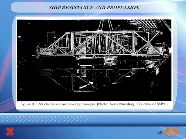
Слайд 46SHIP RESISTANCE AND PROPULSION
46
SHIP RESISTANCE AND PROPULSION
46

Слайд 47SHIP RESISTANCE AND PROPULSION
46
SHIP RESISTANCE AND PROPULSION
46
Слайд 48SHIP RESISTANCE AND PROPULSION
46
SHIP RESISTANCE AND PROPULSION
46
Слайд 49STRENGTH OF SHIPS
32
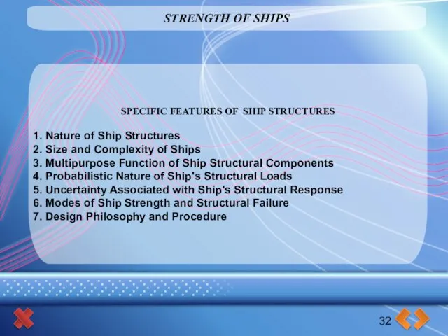
SPECIFIC FEATURES OF SHIP STRUCTURES
1. Nature of Ship Structures
2.
STRENGTH OF SHIPS
32
SPECIFIC FEATURES OF SHIP STRUCTURES
1. Nature of Ship Structures
2.
 Число 0. Цифра 0
 Цветочные мотивы в китайской живописи
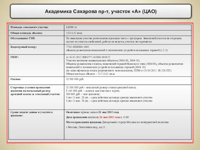 Академика Сахарова пр-т, участок «А» (ЦАО)
 Иуда Искариот
 УЧИМСЯ ПО-НОВОМУ
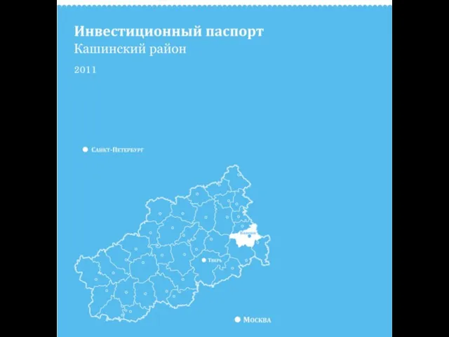 3 Уважаемые господа! Представляем вашему вниманию инвестиционный паспорт Кашинского района. Кашинский район находится в самом цен
 Конференция по литературе
 Кабели автоматики, телемеханики и связи Классификация
 Птица года-варакушка
 Желтый блокнот. Этапы работы
 Дорога на выборы
 Отрасли фундаментальной психологии
 Представление о сетях
 Особенности правопри-менения в МЧП
 Constructions impersonnelles
 Инклюзивное образование. Принципы, перспективы развития
 Типы маркетинга в зависимости от типа спроса
 Лекция 4. Строительство дорожных оснований и покрытий из каменных материалов
 Сделано в Китае: особенности национального бизнеса
 Виды корней. Типы корневых систем
 Административные правоотношения
 Альберт Эйнштейн
 СТУДЕНЧЕСКАЯ ЮРИДИЧЕСКАЯ КОНСУЛЬТАЦИЯ ДЛЯ МАЛОИМУЩИХ
 Сказочный образ в картинах В.Васнецова.
 Лекция ПТМ - 2
 Презентация на тему Русская икона. Древнерусская живопись
 вода и её свойства
 Особенности покупки Поставщиками электрической энергии для покрытия собственных нужд в условиях НОРЭМ Новый порядок учета собст