- Structural Analysis of Trusses – Method of Joints

Содержание
- 2. Simple Trusses
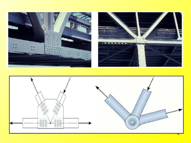
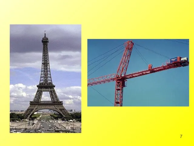
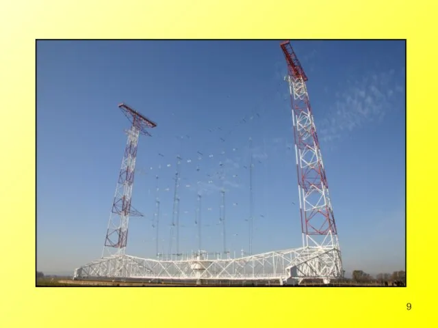
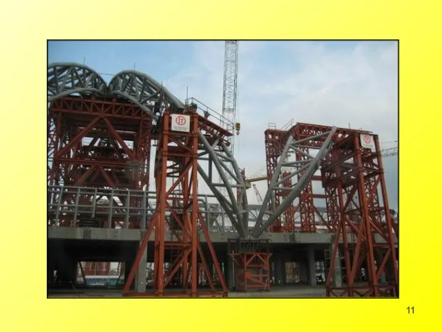
- 3. Truss Definition: A truss is a structure composed of slender members joined together at their end
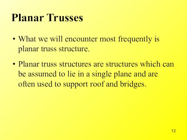
- 12. Planar Trusses What we will encounter most frequently is planar truss structure. Planar truss structures are
- 15. Assumptions for Design To design truss structure and its connections, it is first necessary to determine
- 16. General assumptions concerning truss structures are: All loadings are applied at the joints The weights of
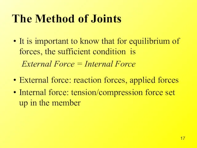
- 17. The Method of Joints It is important to know that for equilibrium of forces, the sufficient
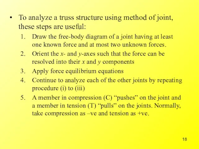
- 18. To analyze a truss structure using method of joint, these steps are useful: Draw the free-body
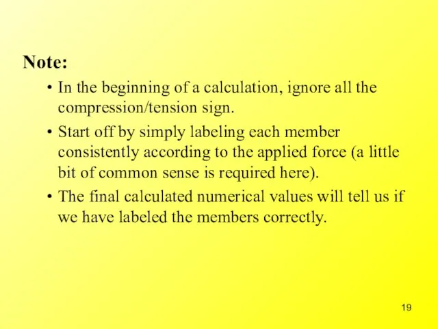
- 19. Note: In the beginning of a calculation, ignore all the compression/tension sign. Start off by simply
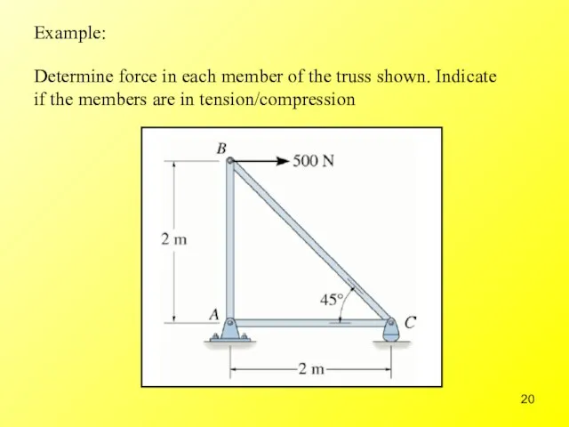
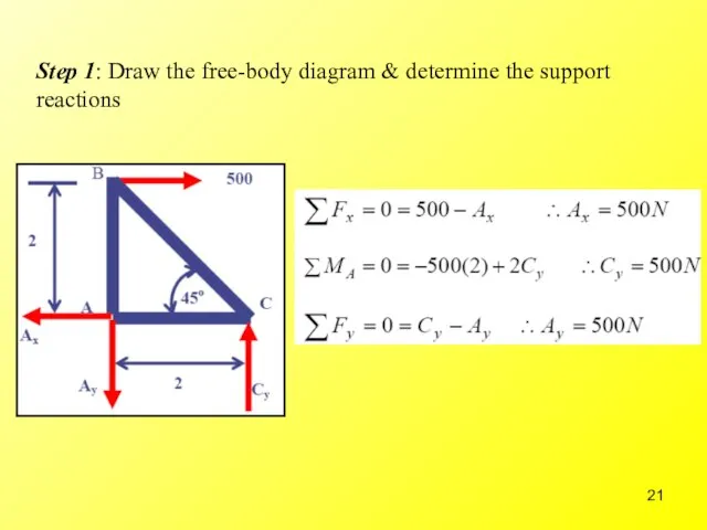
- 20. Example: Determine force in each member of the truss shown. Indicate if the members are in
- 21. Step 1: Draw the free-body diagram & determine the support reactions
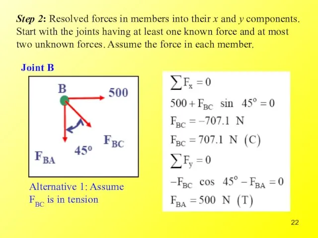
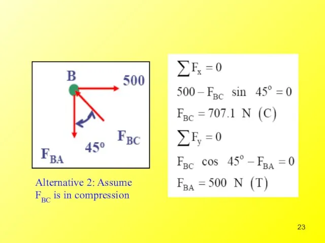
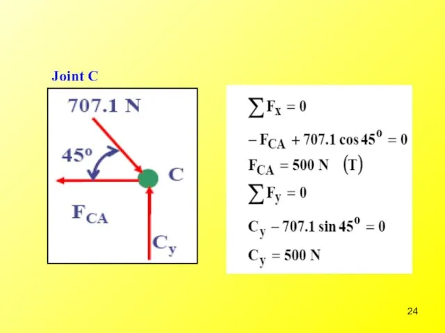
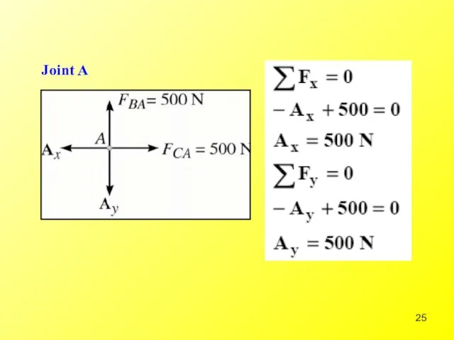
- 22. Step 2: Resolved forces in members into their x and y components. Start with the joints
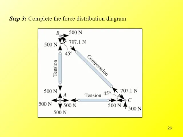
- 26. Step 3: Complete the force distribution diagram
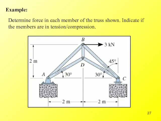
- 27. Example: Determine force in each member of the truss shown. Indicate if the members are in
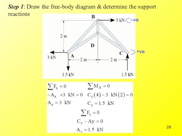
- 28. Step 1: Draw the free-body diagram & determine the support reactions D
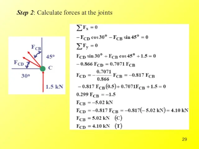
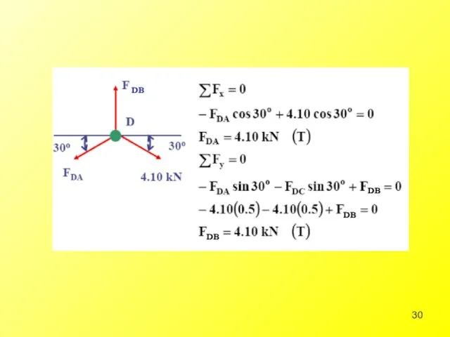
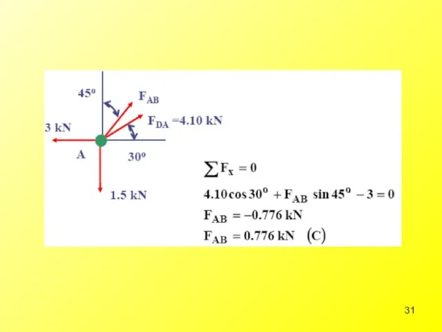
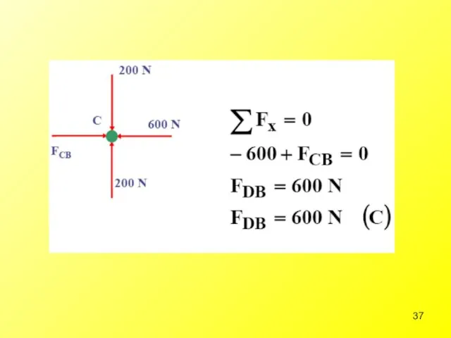
- 29. Step 2: Calculate forces at the joints
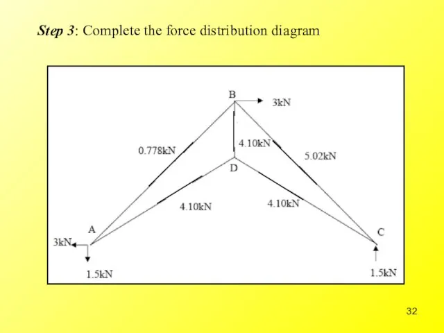
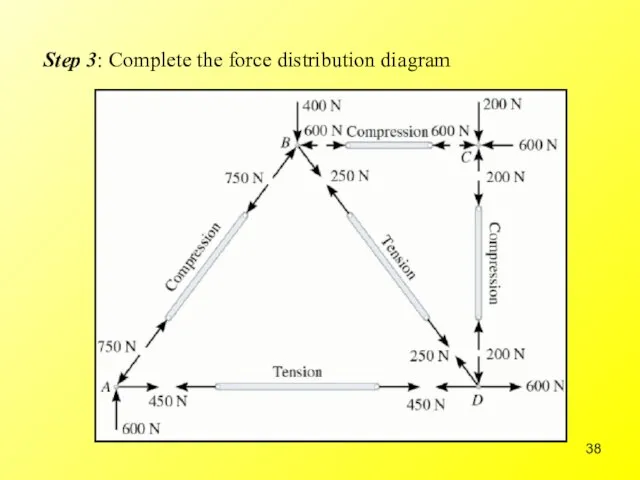
- 32. Step 3: Complete the force distribution diagram
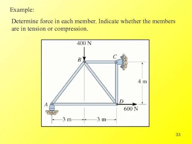
- 33. Determine force in each member. Indicate whether the members are in tension or compression. Example:
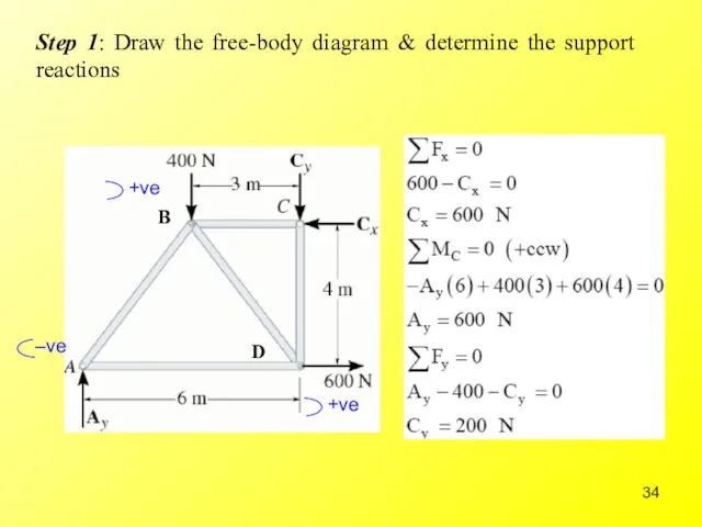
- 34. Step 1: Draw the free-body diagram & determine the support reactions B D
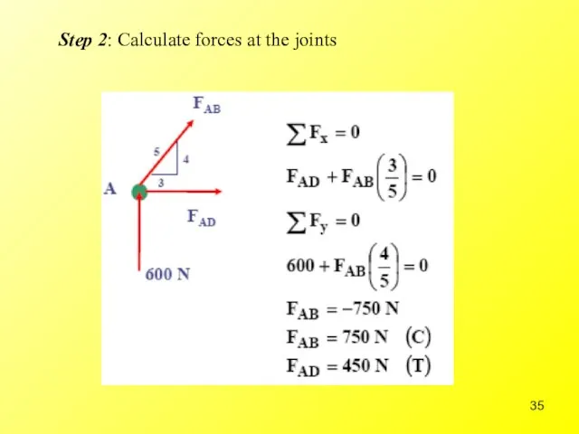
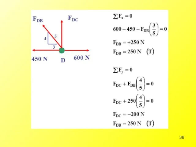
- 35. Step 2: Calculate forces at the joints
- 38. Step 3: Complete the force distribution diagram
- 39. Structural Analysis of Trusses – Method of Sections
- 40. Zero-Force Members Our analysis can be greatly simplified if one can identify those members that support
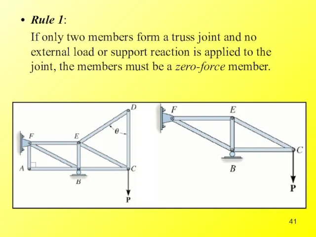
- 41. Rule 1: If only two members form a truss joint and no external load or support
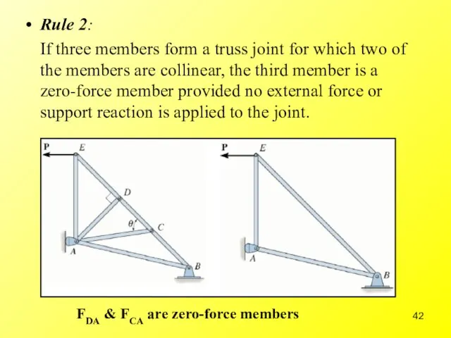
- 42. Rule 2: If three members form a truss joint for which two of the members are
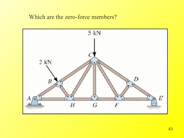
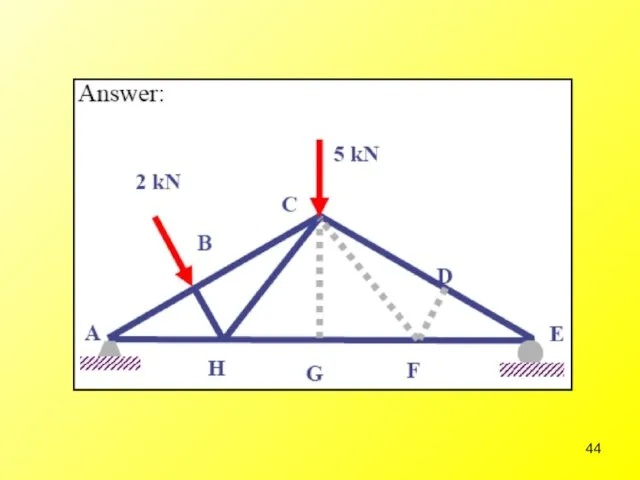
- 43. Which are the zero-force members?
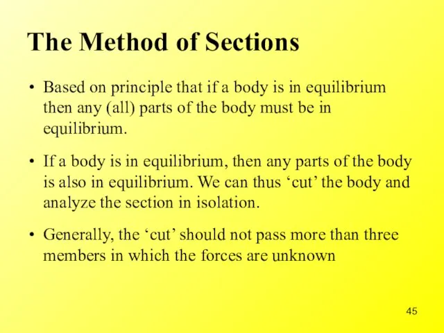
- 45. The Method of Sections Based on principle that if a body is in equilibrium then any
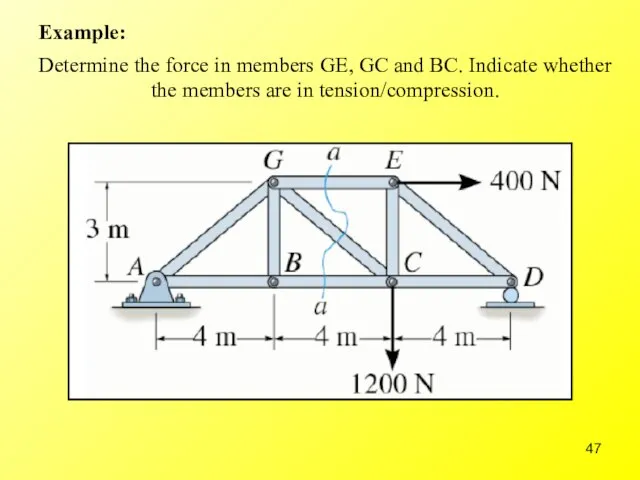
- 47. Determine the force in members GE, GC and BC. Indicate whether the members are in tension/compression.
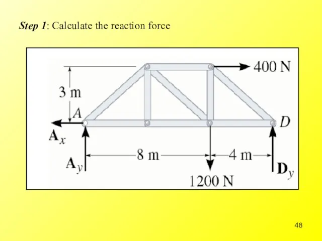
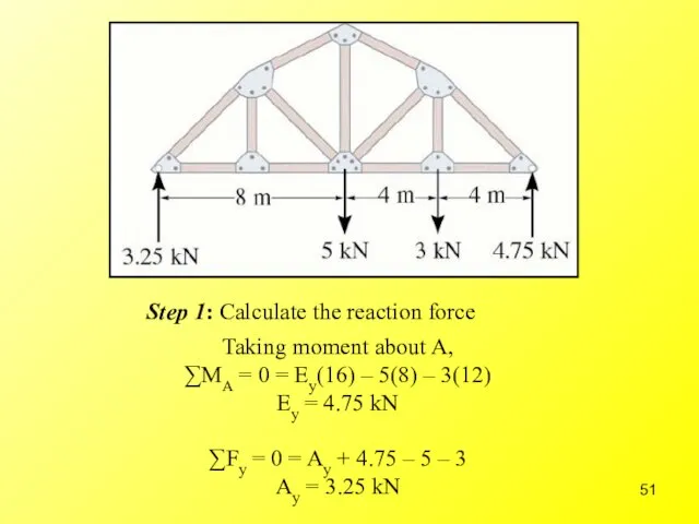
- 48. Step 1: Calculate the reaction force
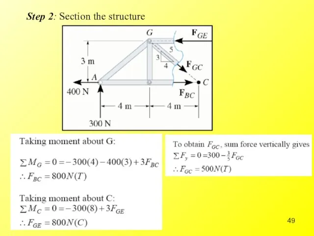
- 49. Step 2: Section the structure
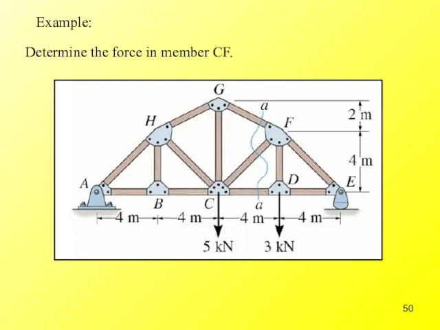
- 50. Example: Determine the force in member CF.
- 51. Taking moment about A, ∑MA = 0 = Ey(16) – 5(8) – 3(12) Ey = 4.75
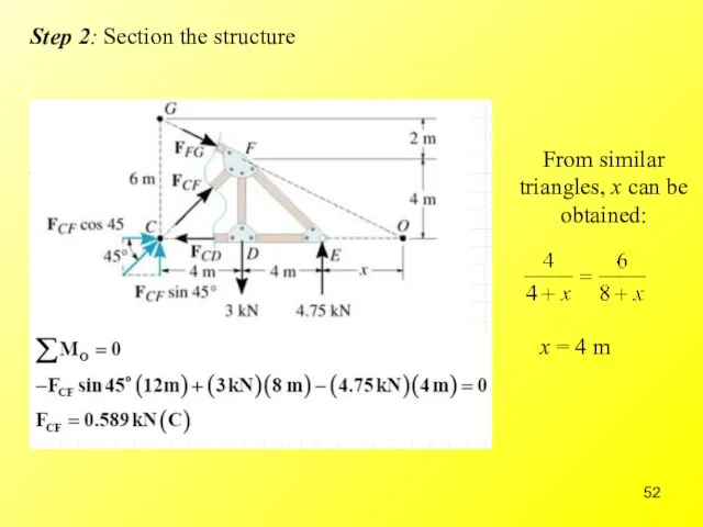
- 52. Step 2: Section the structure
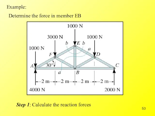
- 53. Example: Determine the force in member EB Step 1: Calculate the reaction forces
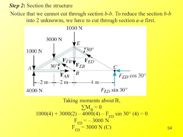
- 54. Step 2: Section the structure Notice that we cannot cut through section b-b. To reduce the
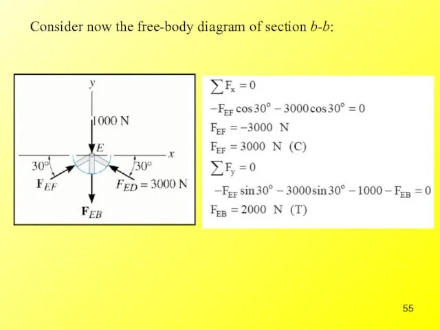
- 55. Consider now the free-body diagram of section b-b:
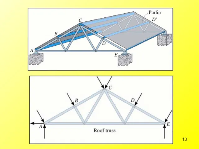
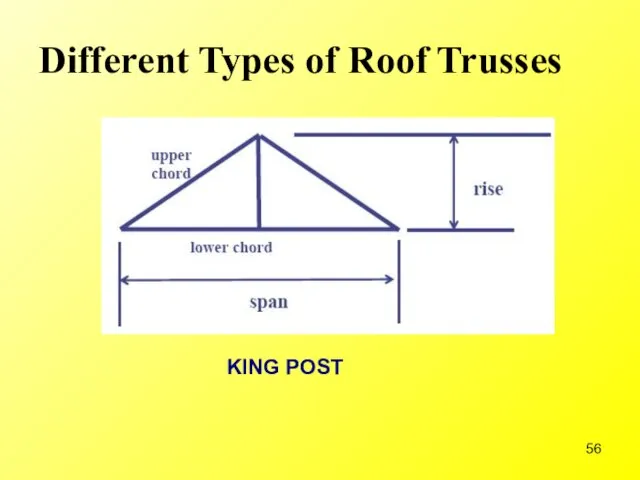
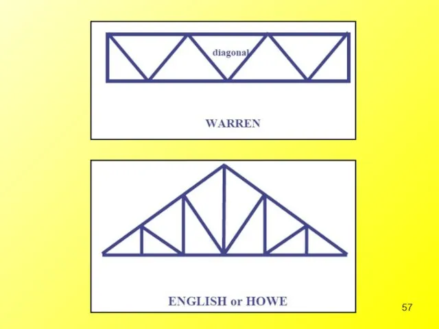
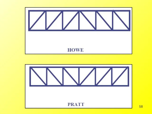
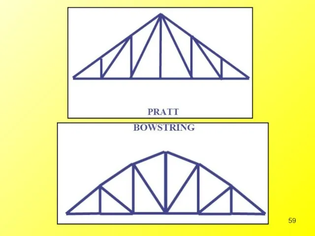
- 56. Different Types of Roof Trusses
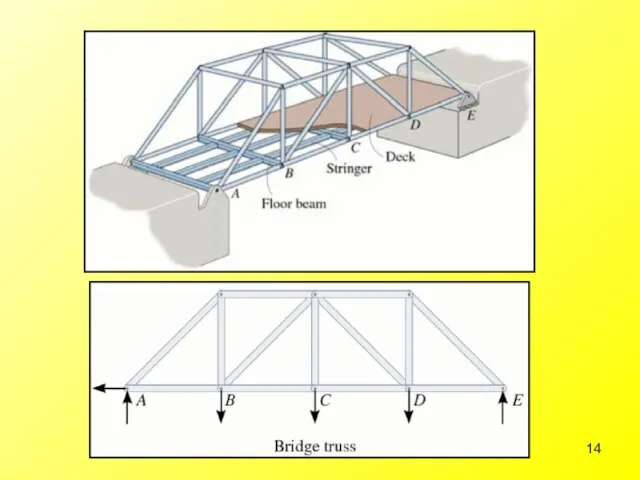
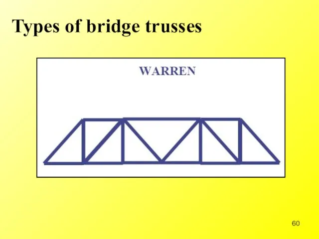
- 60. Types of bridge trusses
- 62. Скачать презентацию
Слайд 3Truss
Definition: A truss is a structure composed of slender members joined together
Truss
Definition: A truss is a structure composed of slender members joined together


Слайд 12Planar Trusses
What we will encounter most frequently is planar truss structure.
Planar
Planar Trusses
What we will encounter most frequently is planar truss structure.
Planar
Слайд 15Assumptions for Design
To design truss structure and its connections, it is first
Assumptions for Design
To design truss structure and its connections, it is first
Слайд 16General assumptions concerning truss structures are:
All loadings are applied at the
General assumptions concerning truss structures are:
All loadings are applied at the
Слайд 17The Method of Joints
It is important to know that for equilibrium of
The Method of Joints
It is important to know that for equilibrium of
Слайд 18To analyze a truss structure using method of joint, these steps are
To analyze a truss structure using method of joint, these steps are
Слайд 19Note:
In the beginning of a calculation, ignore all the compression/tension sign.
Note:
In the beginning of a calculation, ignore all the compression/tension sign.
Слайд 20Example:
Determine force in each member of the truss shown. Indicate if the
Example:
Determine force in each member of the truss shown. Indicate if the
Слайд 21Step 1: Draw the free-body diagram & determine the support reactions
Step 1: Draw the free-body diagram & determine the support reactions
Слайд 22Step 2: Resolved forces in members into their x and y components.
Step 2: Resolved forces in members into their x and y components.
Слайд 26Step 3: Complete the force distribution diagram
Step 3: Complete the force distribution diagram
Слайд 27Example:
Determine force in each member of the truss shown. Indicate if the
Example:
Determine force in each member of the truss shown. Indicate if the
Слайд 28Step 1: Draw the free-body diagram & determine the support reactions
D
Step 1: Draw the free-body diagram & determine the support reactions
D
Слайд 29Step 2: Calculate forces at the joints
Step 2: Calculate forces at the joints
Слайд 32Step 3: Complete the force distribution diagram
Step 3: Complete the force distribution diagram
Слайд 33Determine force in each member. Indicate whether the members are in tension
Determine force in each member. Indicate whether the members are in tension
Слайд 34Step 1: Draw the free-body diagram & determine the support reactions
B
D
Step 1: Draw the free-body diagram & determine the support reactions
B
D
Слайд 35Step 2: Calculate forces at the joints
Step 2: Calculate forces at the joints
Слайд 38Step 3: Complete the force distribution diagram
Step 3: Complete the force distribution diagram
Слайд 39
Structural Analysis of Trusses – Method of Sections
Structural Analysis of Trusses – Method of Sections
Слайд 40Zero-Force Members
Our analysis can be greatly simplified if one can identify
Zero-Force Members
Our analysis can be greatly simplified if one can identify
Слайд 41Rule 1:
If only two members form a truss joint and no
Rule 1:
If only two members form a truss joint and no
Слайд 42Rule 2:
If three members form a truss joint for which two
Rule 2:
If three members form a truss joint for which two
Слайд 43Which are the zero-force members?
Which are the zero-force members?
Слайд 45The Method of Sections
Based on principle that if a body is in
The Method of Sections
Based on principle that if a body is in
Слайд 47Determine the force in members GE, GC and BC. Indicate whether the
Determine the force in members GE, GC and BC. Indicate whether the
Слайд 48Step 1: Calculate the reaction force
Step 1: Calculate the reaction force
Слайд 49Step 2: Section the structure
Step 2: Section the structure
Слайд 50Example:
Determine the force in member CF.
Example:
Determine the force in member CF.
Слайд 51Taking moment about A,
∑MA = 0 = Ey(16) – 5(8) – 3(12)
Ey
Taking moment about A,
∑MA = 0 = Ey(16) – 5(8) – 3(12)
Ey
Слайд 52Step 2: Section the structure
Step 2: Section the structure
Слайд 53Example:
Determine the force in member EB
Step 1: Calculate the reaction forces
Example:
Determine the force in member EB
Step 1: Calculate the reaction forces
Слайд 54Step 2: Section the structure
Notice that we cannot cut through section
Step 2: Section the structure
Notice that we cannot cut through section
Слайд 55Consider now the free-body diagram of section b-b:
Consider now the free-body diagram of section b-b:
Слайд 56Different Types of Roof Trusses
Different Types of Roof Trusses
Слайд 60Types of bridge trusses
Types of bridge trusses
 www.Ritz-BTR.narod.ru
 Ресурсы и назначения
 Интернет 11 класс
 Мастер – класс Вязка туристических узлов, применение их в туристской деятельности
 реклама
 Фантазии синьора Родари
 Развитие творческих способностей учащихся на уроках информатики
 Оформляем работу интересно и правильно
 Информационно-аналитическая система «Курорты Кубани»
 Правосудие в современной России
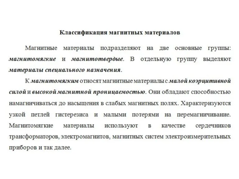 Классификация магнитных материалов
 Психология в экскурсоведении
 Илья Муромец и Соловей-разбойник
 День открытых дверей
 Психолого-педагогические вопросы развития культуры детской социальной инициативы в образовательных учреждениях
 Давыдова Александра. Предвыборная программа кандидата в СС ФМОПИ II созыва
 Исследовательский проектИстория народной медицины
 Внеземные цивилизации
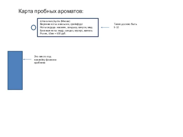 Карта пробных ароматов: Al Haramain/Aysha (милая)
 Презентация на тему Бой у мыса Акций
  Вступление в материаловедение
  Урок русского языка в 5 классеУчитель Сухицкая В.Т.Брянский городской лицей №1имени А.С.Пушкина
 Виды и рода вооружённых Сил РФ. Сухопутные войска
 Движение денежных средств: структура, содержание и аналитические возможности
 Интерференция света
 Санитария и гигиена при приготовлении пищи
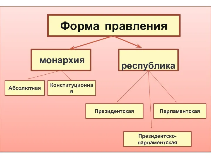 Форма правления
 Презентация на тему Мы против гриппа