- What’s new in InventorCAM 2015

Содержание
- 2. General InventorCAM 2015
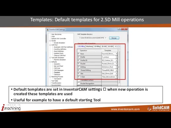
- 3. Templates: Default templates for 2.5D Mill operations Default templates are set in InventorCAM settings ? when
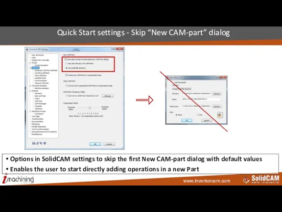
- 4. Quick Start settings - Skip “New CAM-part” dialog Options in SolidCAM settings to skip the first
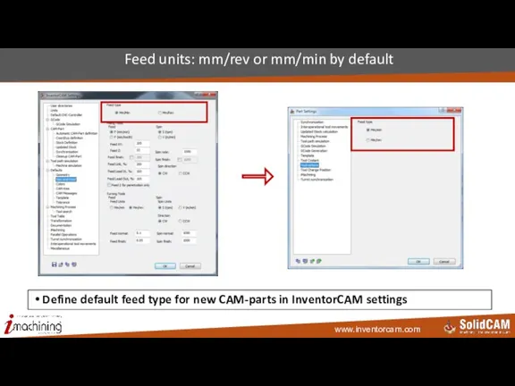
- 5. Feed units: mm/rev or mm/min by default Define default feed type for new CAM-parts in InventorCAM
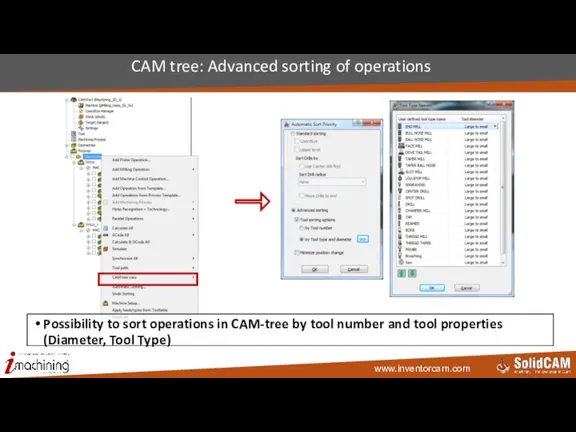
- 6. CAM tree: Advanced sorting of operations Possibility to sort operations in CAM-tree by tool number and
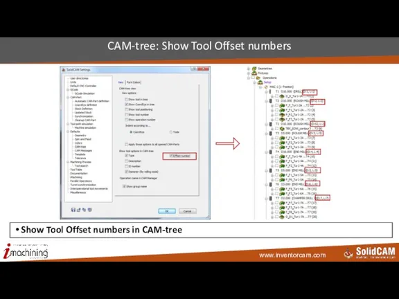
- 7. CAM-tree: Show Tool Offset numbers Show Tool Offset numbers in CAM-tree
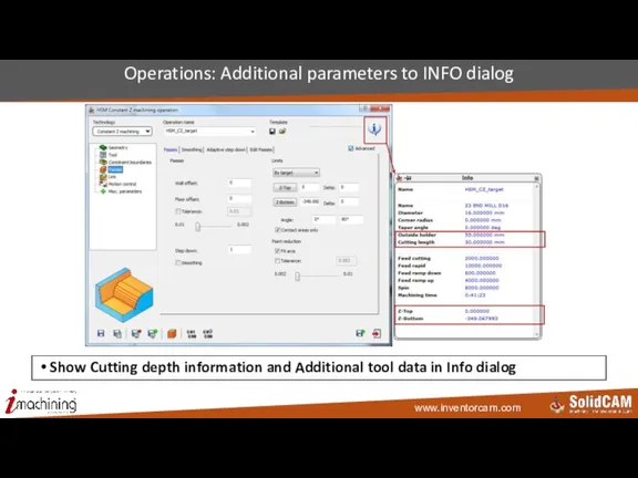
- 8. Operations: Additional parameters to INFO dialog Show Cutting depth information and Additional tool data in Info
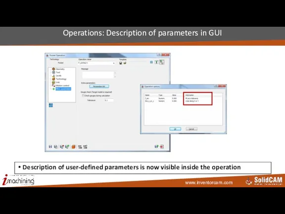
- 9. Operations: Description of parameters in GUI Description of user-defined parameters is now visible inside the operation
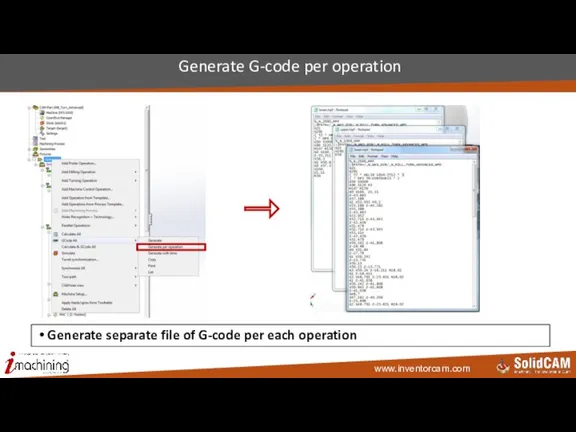
- 10. Generate G-code per operation Generate separate file of G-code per each operation
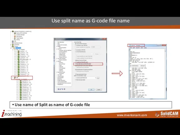
- 11. Use split name as G-code file name Use name of Split as name of G-code file
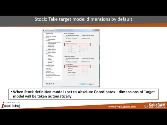
- 12. Stock: Take target model dimensions by default When Stock definition mode is set to Absolute Coordinates
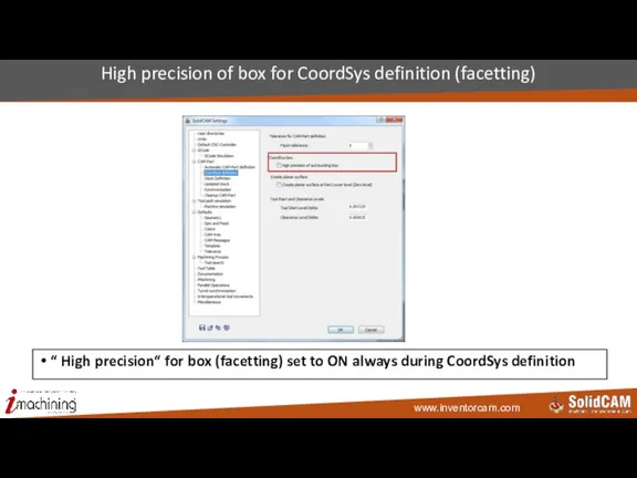
- 13. High precision of box for CoordSys definition (facetting) “ High precision“ for box (facetting) set to
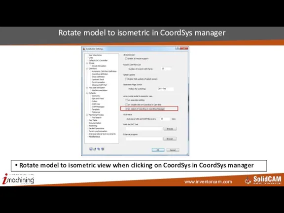
- 14. Rotate model to isometric in CoordSys manager Rotate model to isometric view when clicking on CoordSys
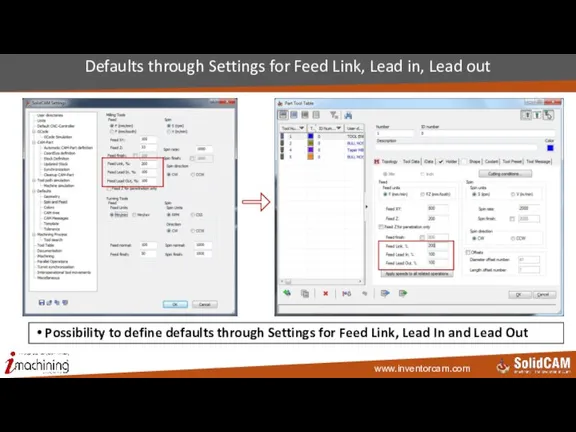
- 15. Defaults through Settings for Feed Link, Lead in, Lead out Possibility to define defaults through Settings
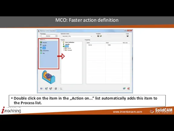
- 16. MCO: Faster action definition Double click on the item in the „Action on...“ list automatically adds
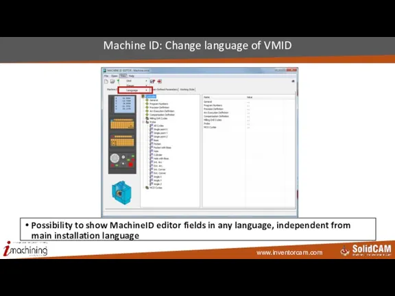
- 17. Machine ID: Change language of VMID Possibility to show MachineID editor fields in any language, independent
- 18. CoordSys InventorCAM 2015
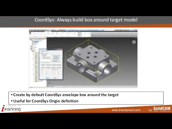
- 19. CoordSys: Always build box around target model Create by default CoordSys envelope box around the target
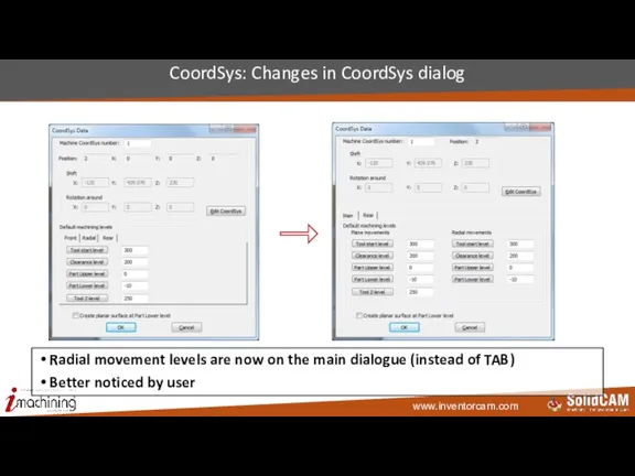
- 20. CoordSys: Changes in CoordSys dialog Radial movement levels are now on the main dialogue (instead of
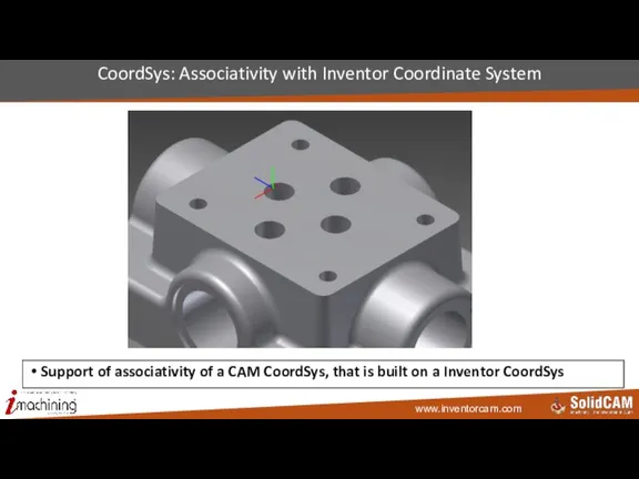
- 21. CoordSys: Associativity with Inventor Coordinate System Support of associativity of a CAM CoordSys, that is built
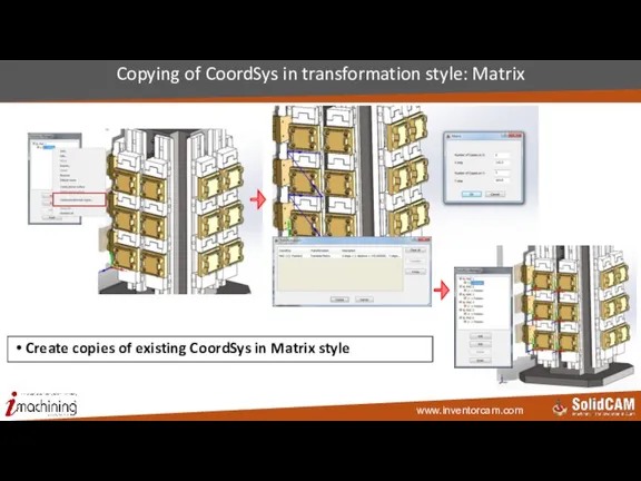
- 22. Copying of CoordSys in transformation style: Matrix Create copies of existing CoordSys in Matrix style
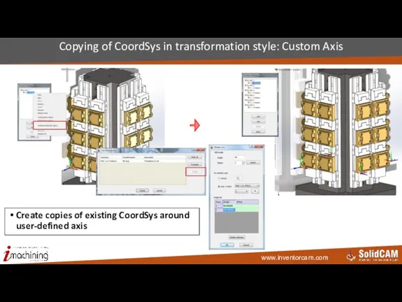
- 23. Copying of CoordSys in transformation style: Custom Axis Create copies of existing CoordSys around user-defined axis
- 24. Copying of CoordSys in transformation style: Combined transformation Combine 2 styles of CoordSys copying User can
- 25. Select all operations of the same CoordSys Fast selection of all operations defined in the Coordsys
- 26. Transformation InventorCAM 2015
- 27. Transform: Matrix without original operation Possibility to make Matrix witout original operation toolpath Useful for postponed
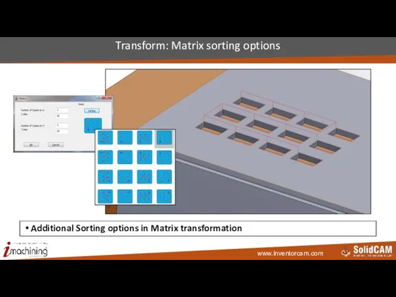
- 28. Transform: Matrix sorting options Additional Sorting options in Matrix transformation
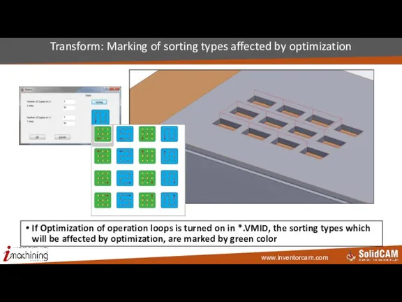
- 29. Transform: Marking of sorting types affected by optimization If Optimization of operation loops is turned on
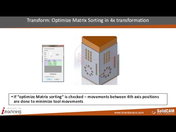
- 30. Transform: Optimize Matrix Sorting in 4x transformation If “optimize Matrix sorting“ is checked – movements between
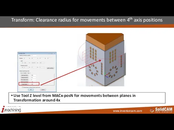
- 31. Transform: Clearance radius for movements between 4th axis positions Use Tool Z level from MACx-posN for
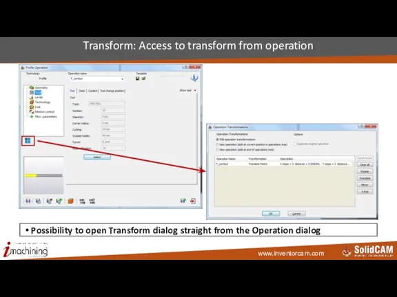
- 32. Transform: Access to transform from operation Possibility to open Transform dialog straight from the Operation dialog
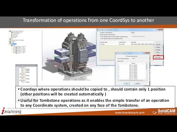
- 33. Transformation of operations from one CoordSys to another Coordsys where operations should be copied to ,
- 34. Tooltable InventorCAM 2015
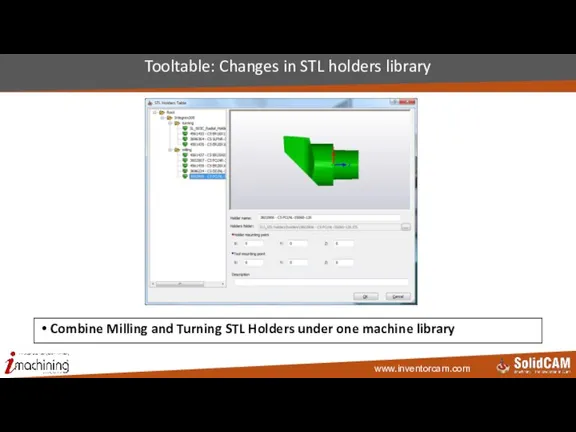
- 35. Tooltable: Changes in STL holders library Combine Milling and Turning STL Holders under one machine library
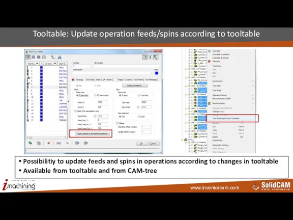
- 36. Tooltable: Update operation feeds/spins according to tooltable Possibilitiy to update feeds and spins in operations according
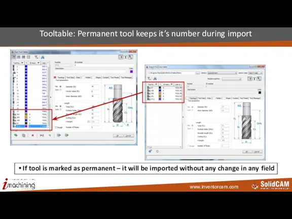
- 37. Tooltable: Permanent tool keeps it’s number during import If tool is marked as permanent – it
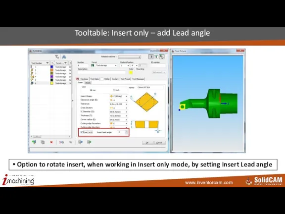
- 38. Tooltable: Insert only – add Lead angle Option to rotate insert, when working in Insert only
- 39. Geometry InventorCAM 2015
- 40. Geometry: Filtering of Pocket Recognition faces by color Select only faces of specified color in Pocket
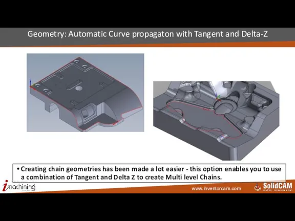
- 41. Geometry: Automatic Curve propagaton with Tangent and Delta-Z Creating chain geometries has been made a lot
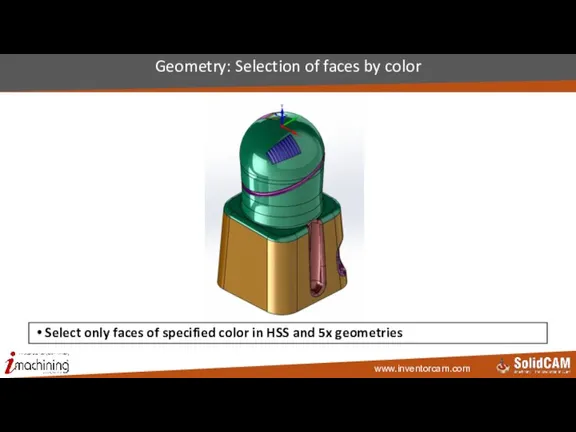
- 42. Geometry: Selection of faces by color Select only faces of specified color in HSS and 5x
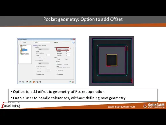
- 43. Pocket geometry: Option to add Offset Option to add offset to geometry of Pocket operation Enable
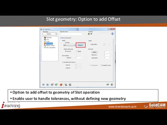
- 44. Slot geometry: Option to add Offset Option to add offset to geometry of Slot operation Enable
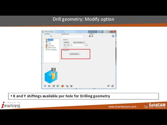
- 45. Drill geometry: Modify option X and Y shiftings available per hole for Drilling geometry
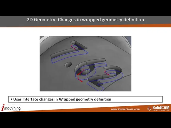
- 46. 2D Geometry: Changes in wrapped geometry definition User Interface changes in Wrapped geometry definition
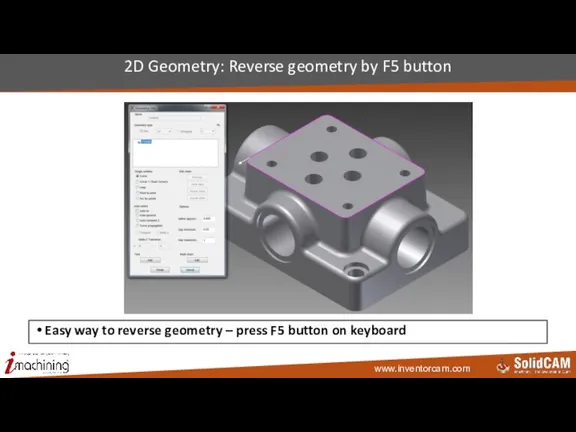
- 47. 2D Geometry: Reverse geometry by F5 button Easy way to reverse geometry – press F5 button
- 48. 2.5D Mill InventorCAM 2015
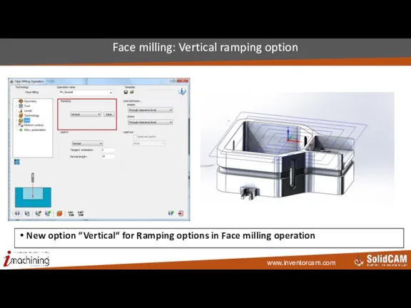
- 49. Face milling: Vertical ramping option New option “Vertical“ for Ramping options in Face milling operation
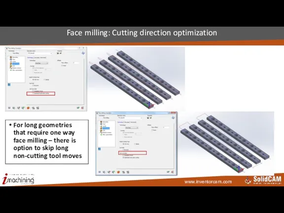
- 50. Face milling: Cutting direction optimization For long geometries that require one way face milling – there
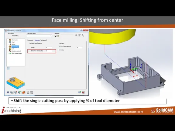
- 51. Face milling: Shifting from center Shift the single cutting pass by applying % of tool diameter
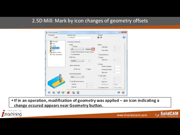
- 52. 2.5D Mill: Mark by icon changes of geometry offsets If in an operation, modification of geometry
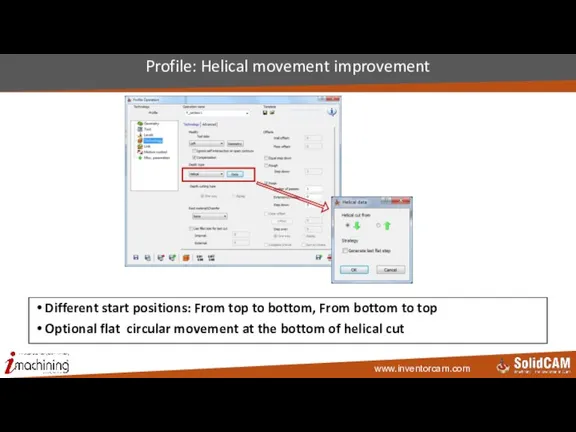
- 53. Profile: Helical movement improvement Different start positions: From top to bottom, From bottom to top Optional
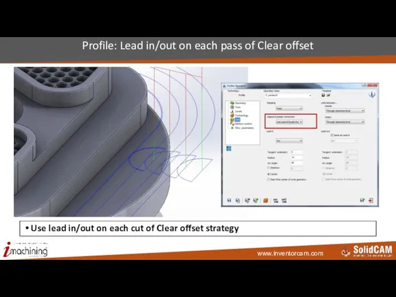
- 54. Profile: Lead in/out on each pass of Clear offset Use lead in/out on each cut of
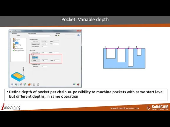
- 55. Pocket: Variable depth Define depth of pocket per chain => possibility to machine pockets with same
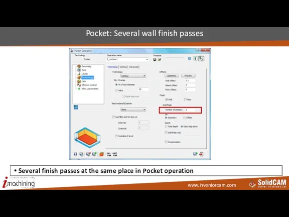
- 56. Pocket: Several wall finish passes Several finish passes at the same place in Pocket operation
- 57. Toolbox InventorCAM 2015
- 58. Toolbox: Angled cylinder Machining of angled cylinder Minimizing air cuts
- 59. Toolbox: Saw machining Special strategy for wood cutting
- 60. Toolbox: Rib face milling Cleaning of rib faces
- 61. Toolbox: Roll into closed slot Constant tool loading, when entering a closed slot
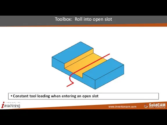
- 62. Toolbox: Roll into open slot Constant tool loading when entering an open slot
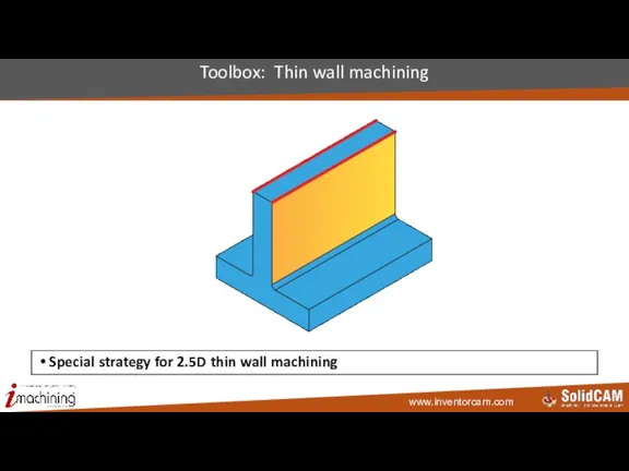
- 63. Toolbox: Thin wall machining Special strategy for 2.5D thin wall machining
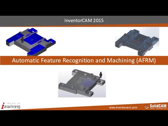
- 64. InventorCAM 2015 Automatic Feature Recognition and Machining (AFRM)
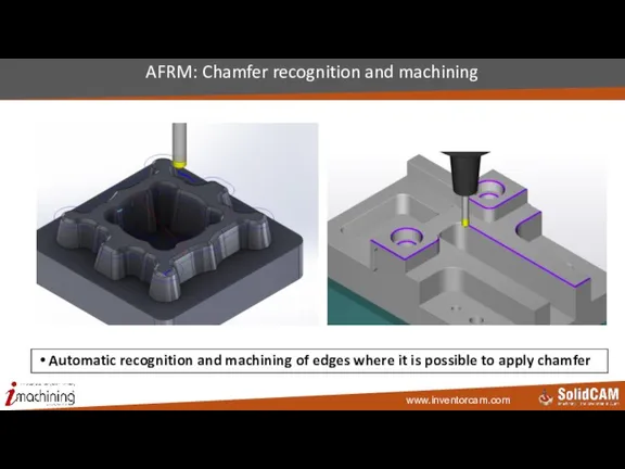
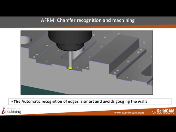
- 65. AFRM: Chamfer recognition and machining Automatic recognition and machining of edges where it is possible to
- 66. AFRM: Chamfer recognition and machining The Automatic recognition of edges is smart and avoids gouging the
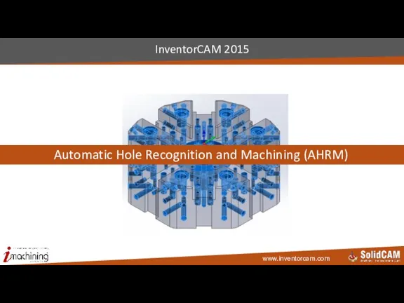
- 67. Automatic Hole Recognition and Machining (AHRM) InventorCAM 2015
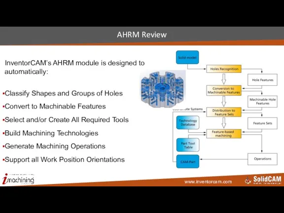
- 68. AHRM Review InventorCAM’s AHRM module is designed to automatically: Classify Shapes and Groups of Holes Convert
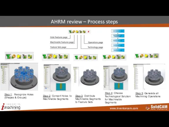
- 69. AHRM review – Process steps Step 1: Recognize Holes (Shapes & Groups) Step 2: Convert Holes
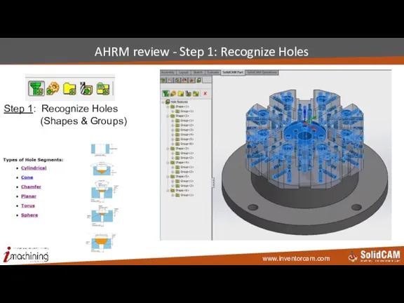
- 70. AHRM review - Step 1: Recognize Holes Step 1: Recognize Holes (Shapes & Groups)
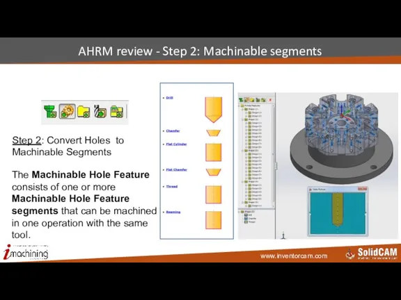
- 71. AHRM review - Step 2: Machinable segments Step 2: Convert Holes to Machinable Segments The Machinable
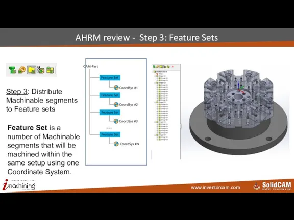
- 72. AHRM review - Step 3: Feature Sets Step 3: Distribute Machinable segments to Feature sets Feature
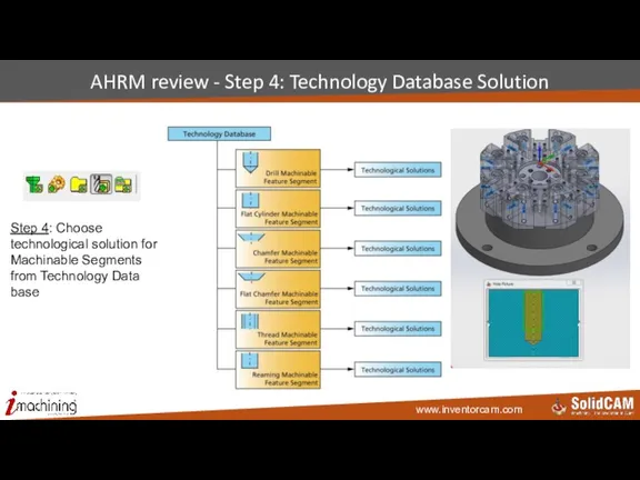
- 73. AHRM review - Step 4: Technology Database Solution Step 4: Choose technological solution for Machinable Segments
- 74. AHRM review - Step 5: Machining Operations Step 5: Generate all machining operations
- 75. AHRM New: Limitless number of DataBase configurations The user can: Define as many DataBases as he
- 76. AHRM New: Machinable feature parameters (mf_xxx) Parameters of machinable features are now available with prefix “mf_”,
- 77. AHRM New: Conditional Logic Support Apply different values to parameters, according to user-defined condition in the
- 78. iMachining 2D & 3D InventorCAM2015
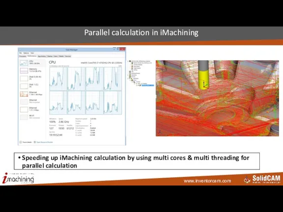
- 79. Parallel calculation in iMachining Speeding up iMachining calculation by using multi cores & multi threading for
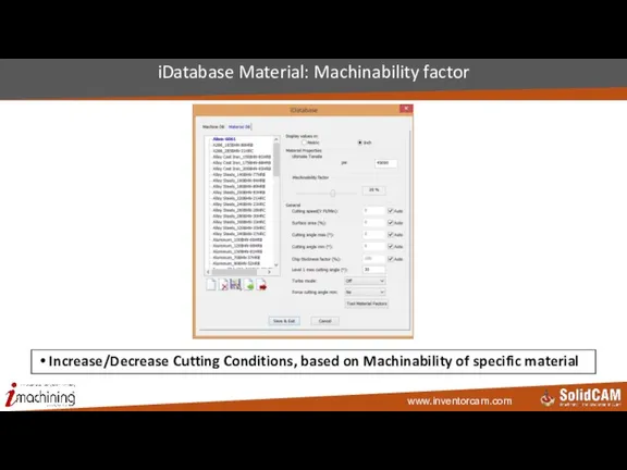
- 80. iDatabase Material: Machinability factor Increase/Decrease Cutting Conditions, based on Machinability of specific material
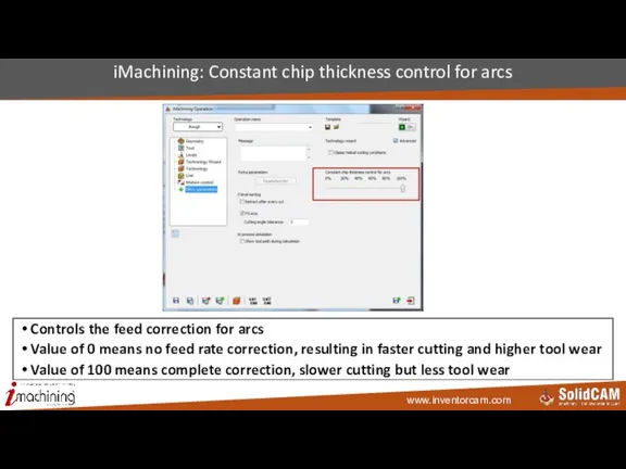
- 81. iMachining: Constant chip thickness control for arcs Controls the feed correction for arcs Value of 0
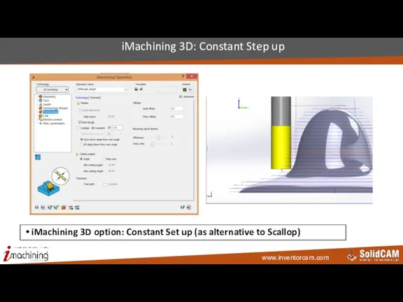
- 82. iMachining 3D: Constant Step up iMachining 3D option: Constant Set up (as alternative to Scallop)
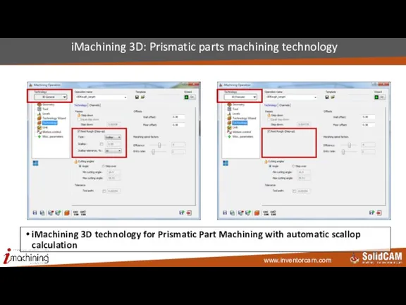
- 83. iMachining 3D: Prismatic parts machining technology iMachining 3D technology for Prismatic Part Machining with automatic scallop
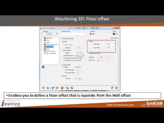
- 84. iMachining 3D: Floor offset Enables you to define a Floor offset that is separate from the
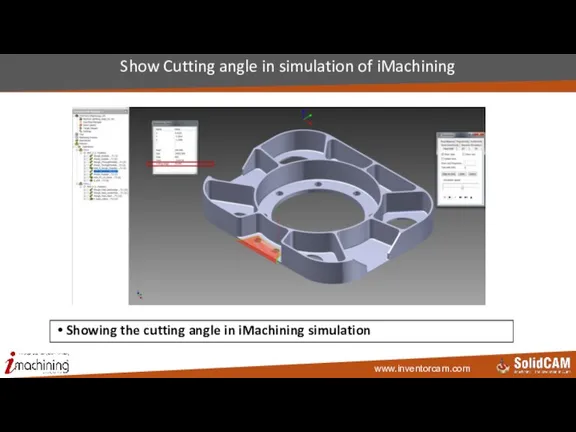
- 85. Show Cutting angle in simulation of iMachining Showing the cutting angle in iMachining simulation
- 86. 3D Milling InventorCAM 2015
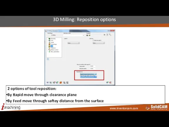
- 87. 3D Milling: Reposition options 2 options of tool reposition: By Rapid move through clearance plane By
- 88. HSR/HSM InventorCAM 2015
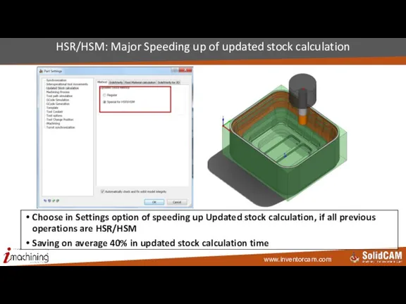
- 89. HSR/HSM: Major Speeding up of updated stock calculation Choose in Settings option of speeding up Updated
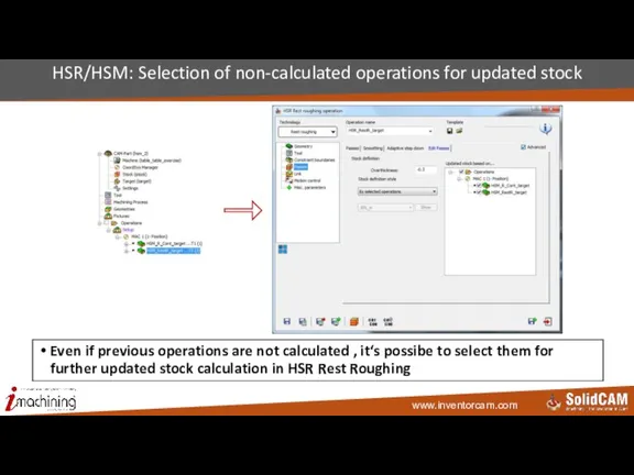
- 90. HSR/HSM: Selection of non-calculated operations for updated stock Even if previous operations are not calculated ,
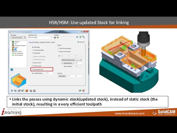
- 91. HSR/HSM: Use updated Stock for linking Links the passes using dynamic stock(updated stock), instead of static
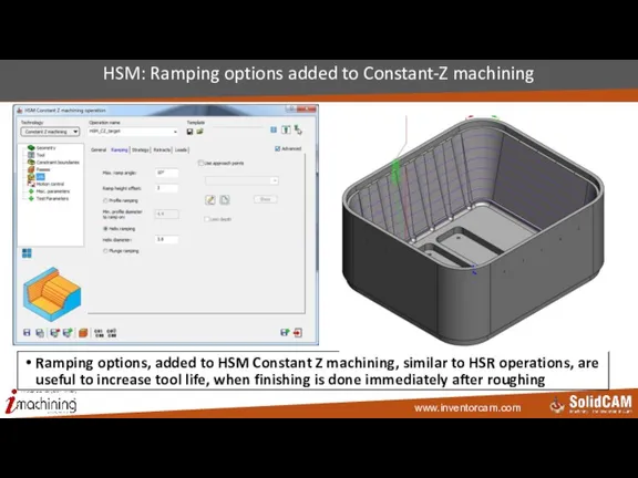
- 92. HSM: Ramping options added to Constant-Z machining Ramping options, added to HSM Constant Z machining, similar
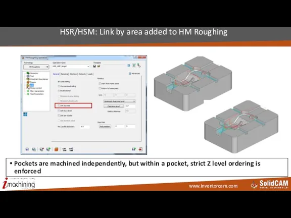
- 93. HSR/HSM: Link by area added to HM Roughing Pockets are machined independently, but within a pocket,
- 94. Sim 5X Milling & HSS InventorCAM 2015
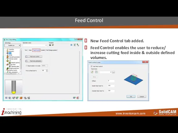
- 95. New Feed Control tab added. Feed Control enables the user to reduce/ increase cutting feed inside
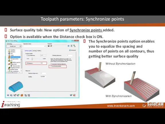
- 96. Surface quality tab: New option of Synchronize points added. Option is available when the Distance check
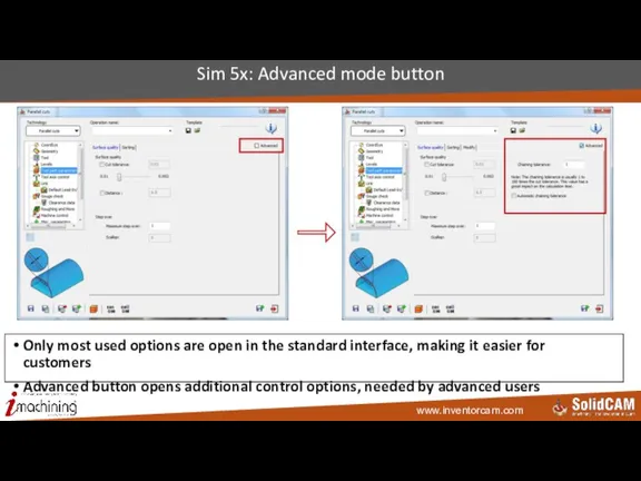
- 97. Sim 5x: Advanced mode button Only most used options are open in the standard interface, making
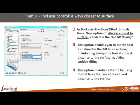
- 98. In Tool axis direction/Tilted through lines: New option of Always closest to surface is added in
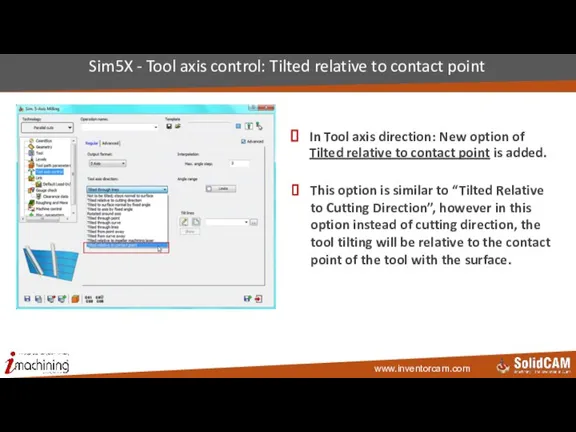
- 99. In Tool axis direction: New option of Tilted relative to contact point is added. Sim5X -
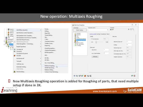
- 100. New Multiaxis Roughing operation is added for Roughing of parts, that need multiple setup if done
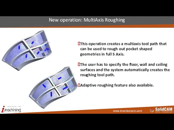
- 101. New operation: MultiAxis Roughing This operation creates a multiaxis tool path that can be used to
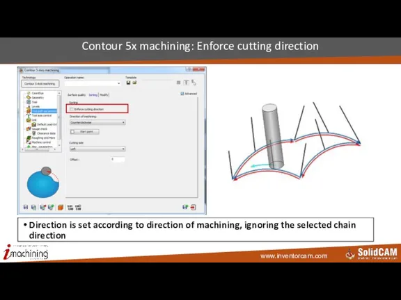
- 102. Contour 5x machining: Enforce cutting direction Direction is set according to direction of machining, ignoring the
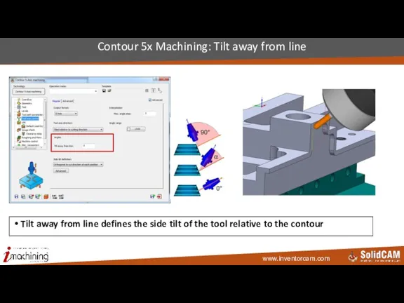
- 103. Contour 5x Machining: Tilt away from line Tilt away from line defines the side tilt of
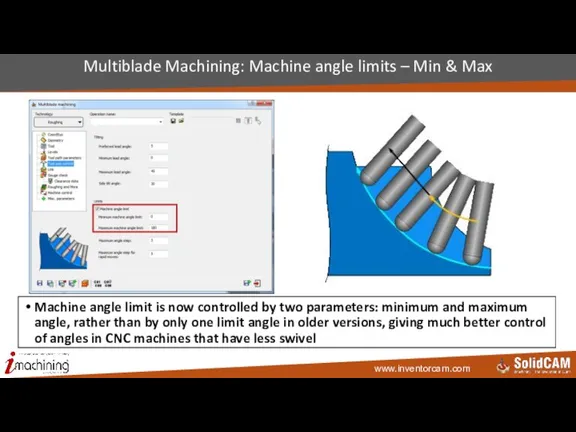
- 104. Multiblade Machining: Machine angle limits – Min & Max Machine angle limit is now controlled by
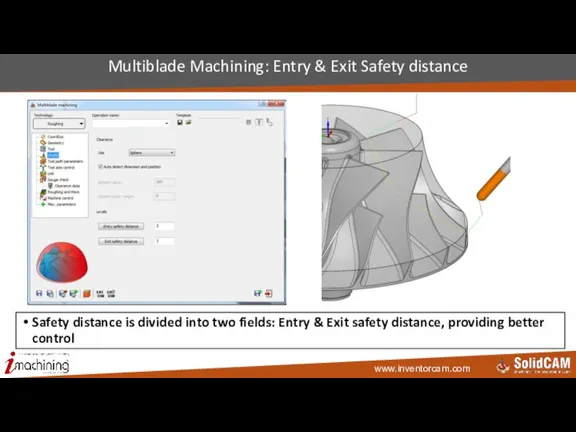
- 105. Multiblade Machining: Entry & Exit Safety distance Safety distance is divided into two fields: Entry &
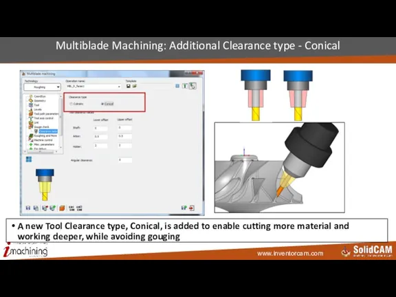
- 106. Multiblade Machining: Additional Clearance type - Conical A new Tool Clearance type, Conical, is added to
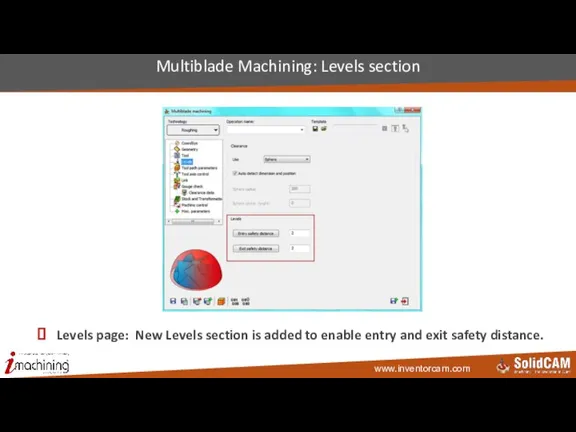
- 107. Levels page: New Levels section is added to enable entry and exit safety distance. Multiblade Machining:
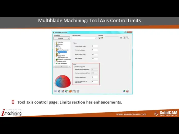
- 108. Tool axis control page: Limits section has enhancements. Multiblade Machining: Tool Axis Control Limits
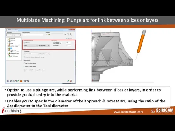
- 109. Multiblade Machining: Plunge arc for link between slices or layers Option to use a plunge arc,
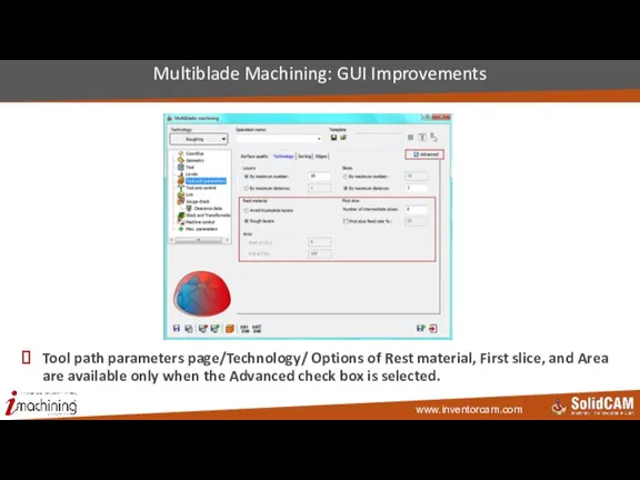
- 110. Tool path parameters page/Technology/ Options of Rest material, First slice, and Area are available only when
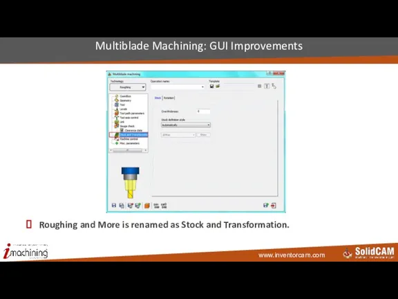
- 111. Roughing and More is renamed as Stock and Transformation. Multiblade Machining: GUI Improvements
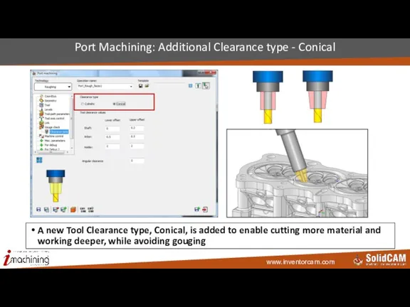
- 112. Port Machining: Additional Clearance type - Conical A new Tool Clearance type, Conical, is added to
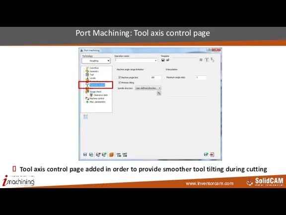
- 113. Port Machining: Tool axis control page Tool axis control page added in order to provide smoother
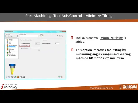
- 114. Tool axis control: Minimize tilting is added. Port Machining: Tool Axis Control - Minimize Tilting This
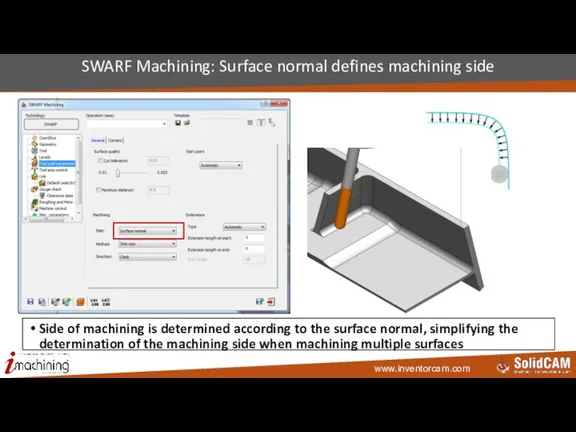
- 115. SWARF Machining: Surface normal defines machining side Side of machining is determined according to the surface
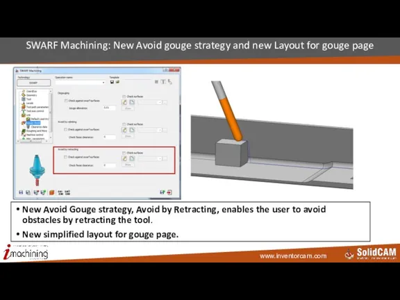
- 116. SWARF Machining: New Avoid gouge strategy and new Layout for gouge page New Avoid Gouge strategy,
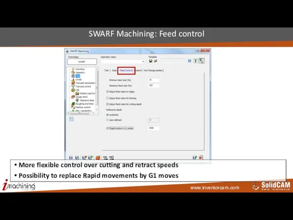
- 117. SWARF Machining: Feed control More flexible control over cutting and retract speeds Possibility to replace Rapid
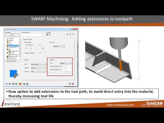
- 118. SWARF Machining: Adding extensions to toolpath New option to add extensions to the tool path, to
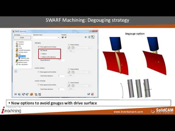
- 119. SWARF Machining: Degouging strategy New options to avoid gouges with drive surface Degouge option
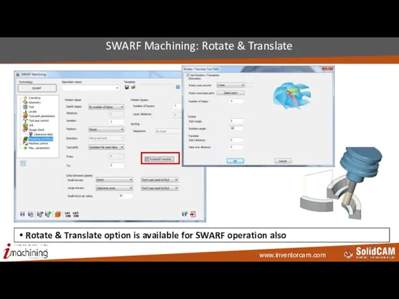
- 120. SWARF Machining: Rotate & Translate Rotate & Translate option is available for SWARF operation also
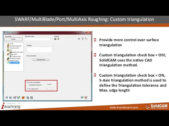
- 121. SWARF/MultiBlade/Port/MultiAxis Roughing: Custom triangulation Provide more control over surface triangulation Custom triangulation check box = OFF,
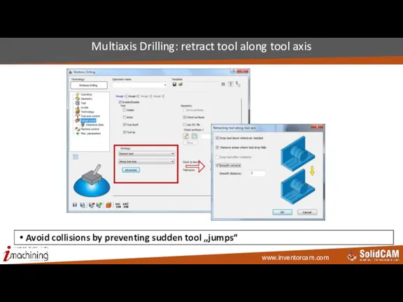
- 122. Multiaxis Drilling: retract tool along tool axis Avoid collisions by preventing sudden tool „jumps“
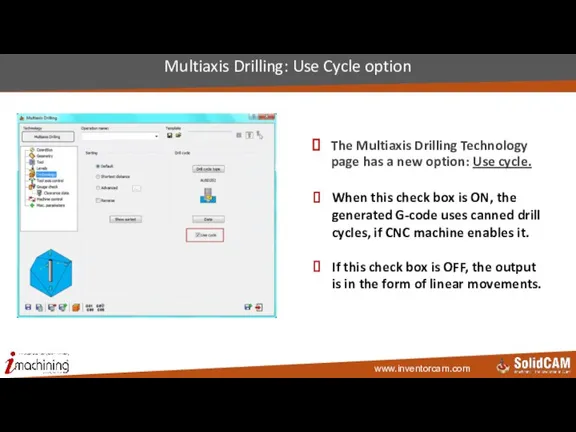
- 123. The Multiaxis Drilling Technology page has a new option: Use cycle. Multiaxis Drilling: Use Cycle option
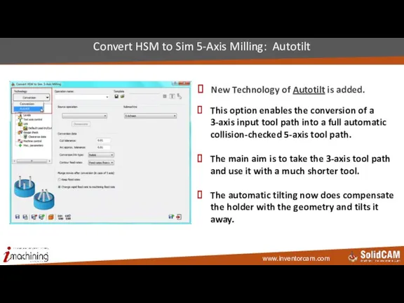
- 124. New Technology of Autotilt is added. Convert HSM to Sim 5-Axis Milling: Autotilt This option enables
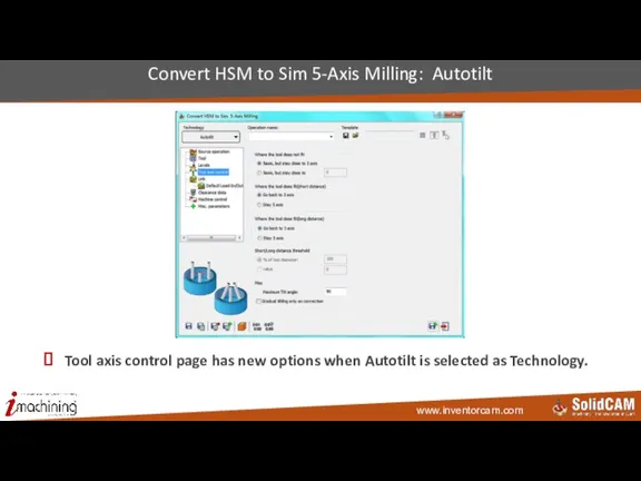
- 125. Tool axis control page has new options when Autotilt is selected as Technology. Convert HSM to
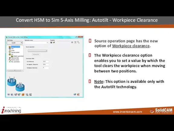
- 126. Source operation page has the new option of Workpiece clearance. Convert HSM to Sim 5-Axis Milling:
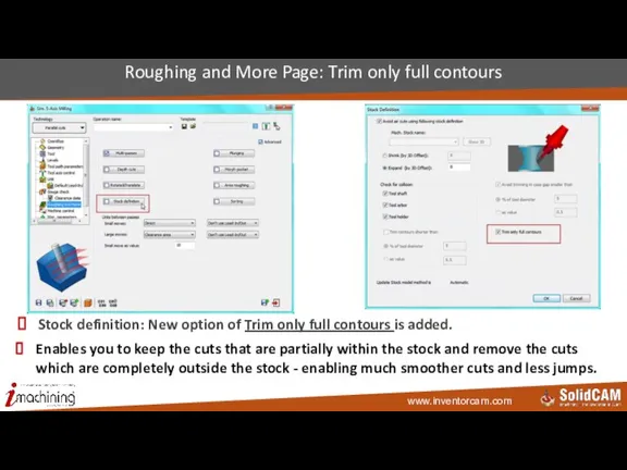
- 127. Stock definition: New option of Trim only full contours is added. Roughing and More Page: Trim
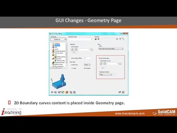
- 128. 2D Boundary curves content is placed inside Geometry page. GUI Changes - Geometry Page
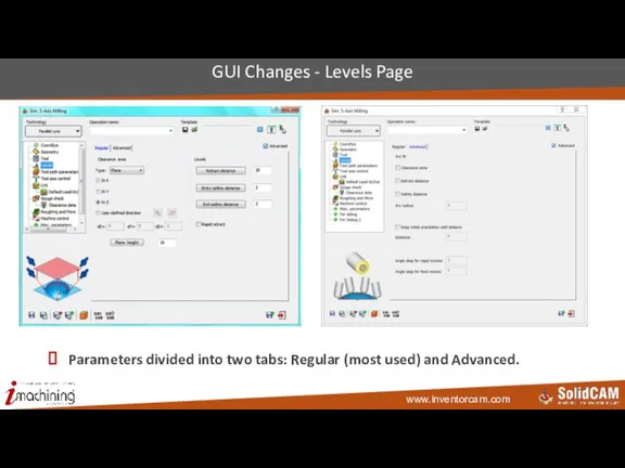
- 129. Parameters divided into two tabs: Regular (most used) and Advanced. GUI Changes - Levels Page
- 130. New Modify tab is added. Round corners, Extend/Trim, and Angle range moved to this page from
- 131. Strategy: Retract along tool axis/ Advanced: New option of Smooth retracts is added. Gouge check Page:
- 132. The Gouge check strategies are logically named Gouge check Page: Renaming of strategies
- 133. Remaining collisions section is updated – one option removed. Gouge check Clearance data Page
- 134. Turning InventorCAM 2015
- 135. Turning: Torochoidal Turning operation iMachining-style torochoidal moves of round grooving tool in turning
- 136. Turning: Use all milling tools in turning drilling Possibility to use Milling tools in Turning Drilling
- 137. Turning: Offset types in face turning Output offset value in Face turning cycle @turning ==> work_type:rough
- 138. Turning: Negative X output Possibility to get (-X) cutting toolpath with start/end points in (+X)
- 139. Turning: Non-descending motion on face surfaces also Option to avoid penetration to slots on face surfaces
- 140. Turning: Auto Lead in/out cancelled In previous versions, an additional movement before Lead in/out was added
- 141. Turning: Lead in/out Used in rough turning also In previous versions, we had only an automatic
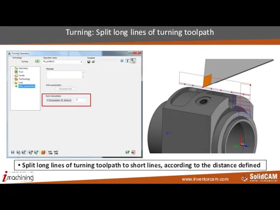
- 142. Turning: Split long lines of turning toolpath Split long lines of turning toolpath to short lines,
- 143. Mill-Turn InventorCAM 2015
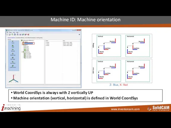
- 144. Machine ID: Machine orientation World CoordSys is always with Z vertically UP Machine orientation (vertical, horizontal)
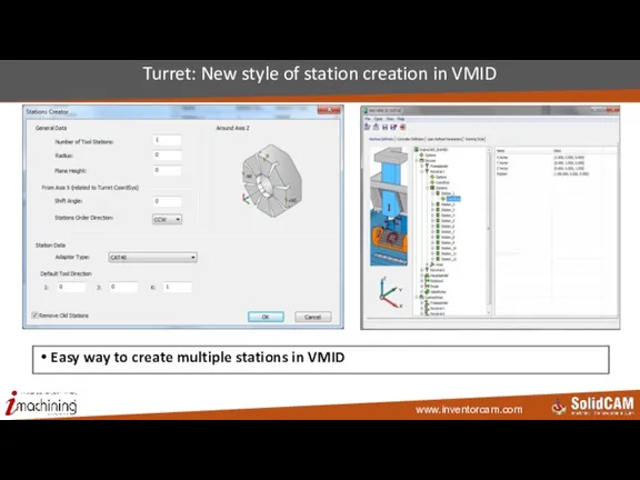
- 145. Turret: New style of station creation in VMID Easy way to create multiple stations in VMID
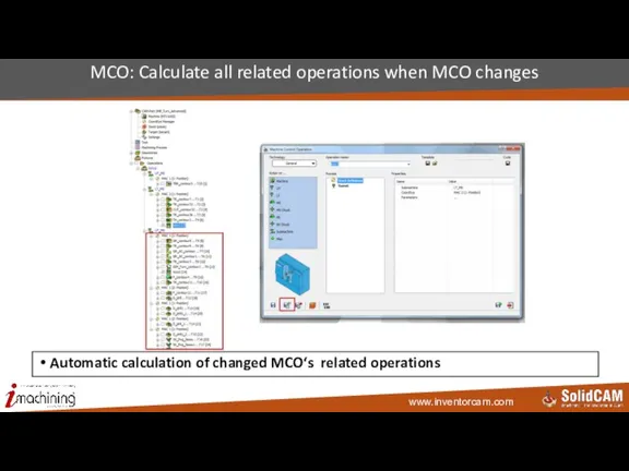
- 146. MCO: Calculate all related operations when MCO changes Automatic calculation of changed MCO‘s related operations
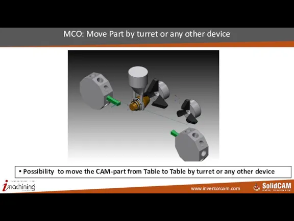
- 147. MCO: Move Part by turret or any other device Possibility to move the CAM-part from Table
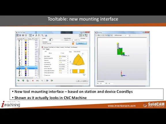
- 148. Tooltable: new mounting interface New tool mounting interface – based on station and device CoordSys Shown
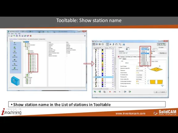
- 149. Tooltable: Show station name Show station name in the List of stations in Tooltable
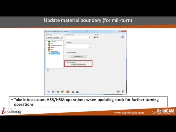
- 150. Update material boundary (for mill-turn) Take into account HSR/HSM operations when updating stock for further turning
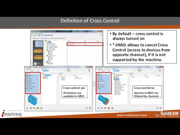
- 151. Definition of Cross Control By default – cross control is always turned on *.VMID allows to
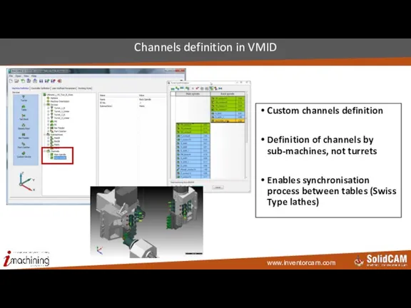
- 152. Channels definition in VMID Custom channels definition Definition of channels by sub-machines, not turrets Enables synchronisation
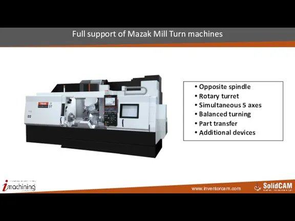
- 153. Full support of Mazak Mill Turn machines Opposite spindle Rotary turret Simultaneous 5 axes Balanced turning
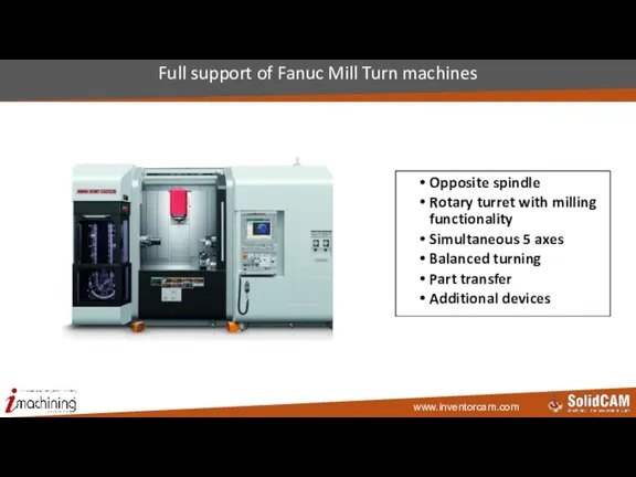
- 154. Full support of Fanuc Mill Turn machines Opposite spindle Rotary turret with milling functionality Simultaneous 5
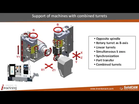
- 155. Support of machines with combined turrets Opposite spindle Rotary turret as B-axis Linear turrets Simultaneous 5
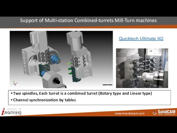
- 156. Support of Multi-station Combined-turrets Mill-Turn machines Two spindles, Each turret is a combined turret (Rotary type
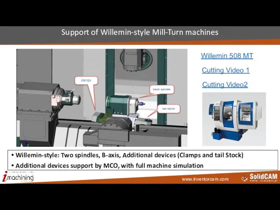
- 157. Support of Willemin-style Mill-Turn machines Willemin-style: Two spindles, B-axis, Additional devices (Clamps and tail Stock) Additional
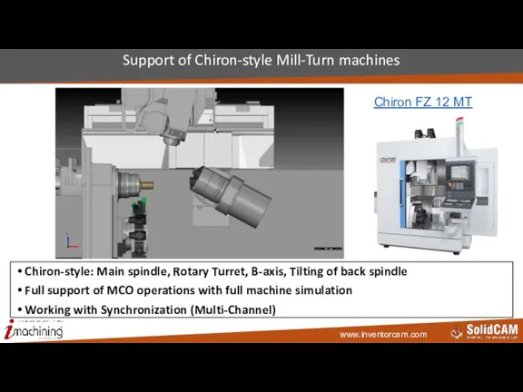
- 158. Support of Chiron-style Mill-Turn machines Chiron-style: Main spindle, Rotary Turret, B-axis, Tilting of back spindle Full
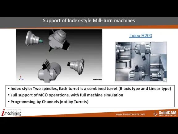
- 159. Support of Index-style Mill-Turn machines Index-style: Two spindles, Each turret is a combined turret (B-axis type
- 160. Simulation InventorCAM2015
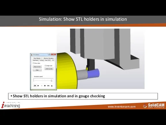
- 161. Simulation: Show STL holders in simulation Show STL holders in simulation and in gouge checking
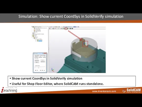
- 162. Simulation: Show current CoordSys in SolidVerify simulation Show current CoordSys in SolidVerify simulation Useful for Shop
- 163. Tool Libraries integrations InventorCAM 2015
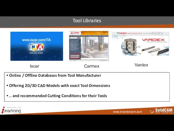
- 164. Tool Libraries Online / Offline Databases from Tool Manufacturer Offering 2D/3D CAD Models with exact Tool
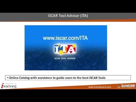
- 165. ISCAR Tool Advisor (ITA) Online Catalog with assistance to guide users to the best ISCAR Tools
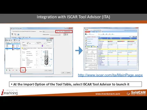
- 166. Integration with ISCAR Tool Advisor (ITA) At the Import Option of the Tool Table, select ISCAR
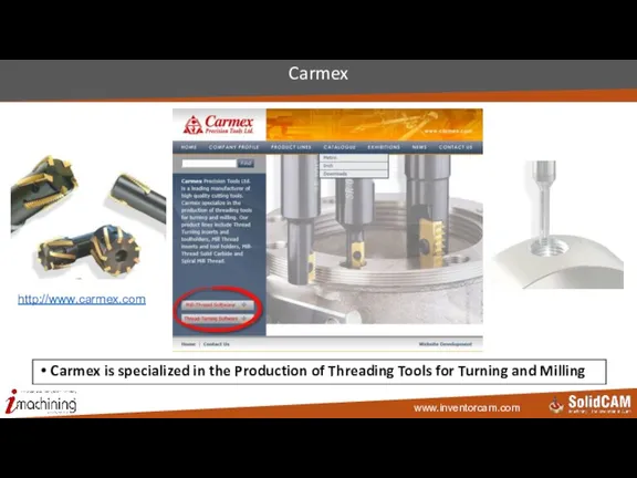
- 167. Carmex Carmex is specialized in the Production of Threading Tools for Turning and Milling http://www.carmex.com
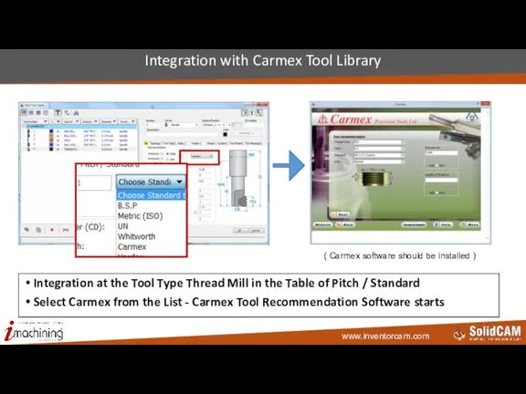
- 168. Integration with Carmex Tool Library ( Carmex software should be installed ) Integration at the Tool
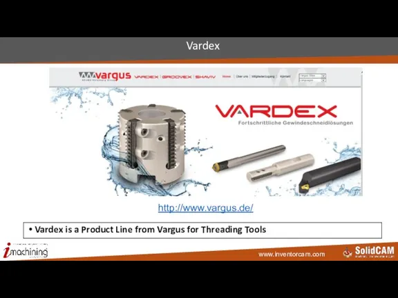
- 169. Vardex Vardex is a Product Line from Vargus for Threading Tools http://www.vargus.de/
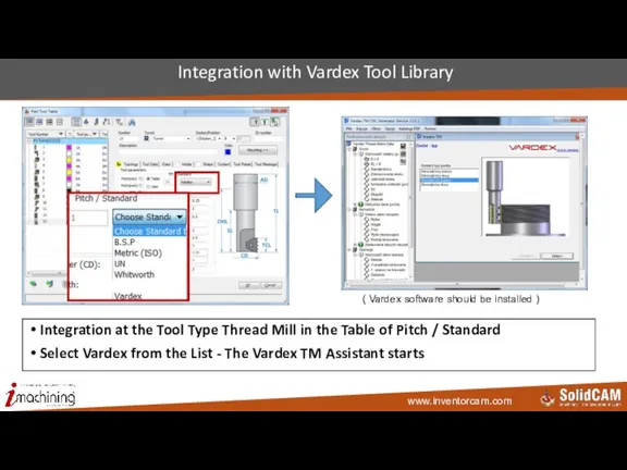
- 170. Integration with Vardex Tool Library ( Vardex software should be installed ) Integration at the Tool
- 171. Tool Management Softwares Integration InventorCAM 2015
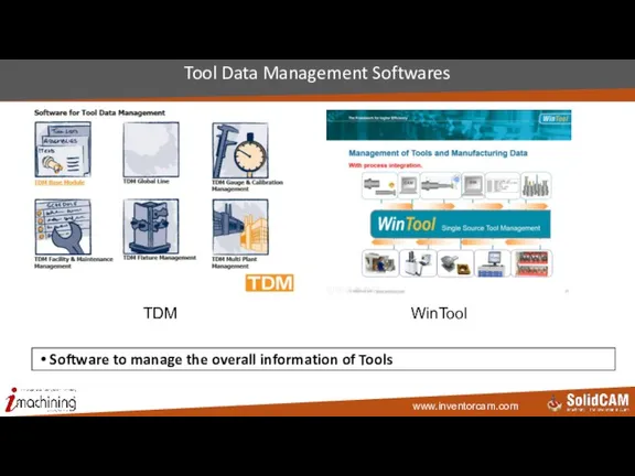
- 172. Tool Data Management Softwares Software to manage the overall information of Tools WinTool TDM
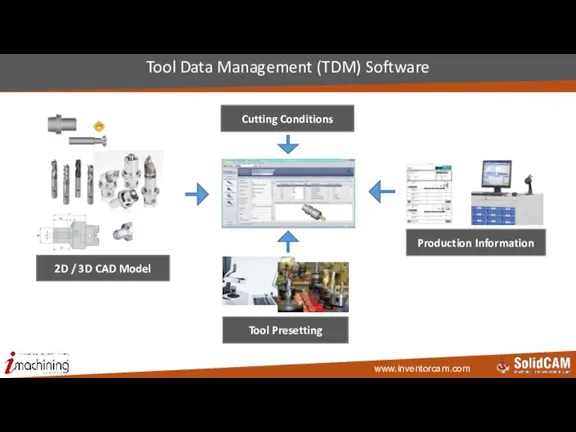
- 173. Tool Data Management (TDM) Software Cutting Conditions 2D / 3D CAD Model Production Information Tool Presetting
- 174. Workflow using TDM Software e.g. downloaded 2D/3D CAD Models Tool with Holder imported from TDM Software
- 175. TDM Version 4.6 http://youtu.be/A3a-jyhMmUY
- 176. Management of Tools and Manufacturing Data in TDM Users collect the models form online Recourses and
- 177. Integration with TDM (TDM should be installed at the Client / Server) Tool Import filtering dialog
- 178. WinTool Professional 2012 For more nformation click to the Logo WinTool - Software for Tool Data
- 179. Management of Tools and Manufacturing Data Users collect the Models form Online Recourses and build the
- 181. Скачать презентацию

Слайд 3 Templates: Default templates for 2.5D Mill operations
Default templates are set in
Templates: Default templates for 2.5D Mill operations
Default templates are set in
Слайд 4 Quick Start settings - Skip “New CAM-part” dialog
Options in SolidCAM settings
Quick Start settings - Skip “New CAM-part” dialog
Options in SolidCAM settings
Слайд 5 Feed units: mm/rev or mm/min by default
Define default feed type for
Feed units: mm/rev or mm/min by default
Define default feed type for
Слайд 6CAM tree: Advanced sorting of operations
Possibility to sort operations in CAM-tree by
CAM tree: Advanced sorting of operations
Possibility to sort operations in CAM-tree by
Слайд 7CAM-tree: Show Tool Offset numbers
Show Tool Offset numbers in CAM-tree
CAM-tree: Show Tool Offset numbers
Show Tool Offset numbers in CAM-tree
Слайд 8Operations: Additional parameters to INFO dialog
Show Cutting depth information and Additional tool
Operations: Additional parameters to INFO dialog
Show Cutting depth information and Additional tool
Слайд 9Operations: Description of parameters in GUI
Description of user-defined parameters is now visible
Operations: Description of parameters in GUI
Description of user-defined parameters is now visible
Слайд 10 Generate G-code per operation
Generate separate file of G-code per each operation
Generate G-code per operation
Generate separate file of G-code per each operation
Слайд 11 Use split name as G-code file name
Use name of Split as
Use split name as G-code file name
Use name of Split as
Слайд 12Stock: Take target model dimensions by default
When Stock definition mode is set
Stock: Take target model dimensions by default
When Stock definition mode is set
Слайд 13High precision of box for CoordSys definition (facetting)
“ High precision“ for
High precision of box for CoordSys definition (facetting)
“ High precision“ for
Слайд 14Rotate model to isometric in CoordSys manager
Rotate model to isometric view when
Rotate model to isometric in CoordSys manager
Rotate model to isometric view when
Слайд 15Defaults through Settings for Feed Link, Lead in, Lead out
Possibility to
Defaults through Settings for Feed Link, Lead in, Lead out
Possibility to
Слайд 16MCO: Faster action definition
Double click on the item in the „Action on...“
MCO: Faster action definition
Double click on the item in the „Action on...“
Слайд 17Machine ID: Change language of VMID
Possibility to show MachineID editor fields in
Machine ID: Change language of VMID
Possibility to show MachineID editor fields in
Слайд 18CoordSys
InventorCAM 2015
CoordSys
InventorCAM 2015

Слайд 19CoordSys: Always build box around target model
Create by default CoordSys envelope box
CoordSys: Always build box around target model
Create by default CoordSys envelope box
Слайд 20CoordSys: Changes in CoordSys dialog
Radial movement levels are now on the main
CoordSys: Changes in CoordSys dialog
Radial movement levels are now on the main
Слайд 21CoordSys: Associativity with Inventor Coordinate System
Support of associativity of a CAM CoordSys,
CoordSys: Associativity with Inventor Coordinate System
Support of associativity of a CAM CoordSys,
Слайд 22Copying of CoordSys in transformation style: Matrix
Create copies of existing CoordSys in
Copying of CoordSys in transformation style: Matrix
Create copies of existing CoordSys in
Слайд 23Copying of CoordSys in transformation style: Custom Axis
Create copies of existing CoordSys
Copying of CoordSys in transformation style: Custom Axis
Create copies of existing CoordSys
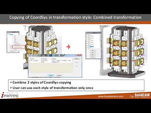
Слайд 24Copying of CoordSys in transformation style: Combined transformation
Combine 2 styles of CoordSys
Copying of CoordSys in transformation style: Combined transformation
Combine 2 styles of CoordSys
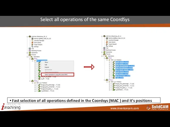
Слайд 25Select all operations of the same CoordSys
Fast selection of all operations defined
Select all operations of the same CoordSys
Fast selection of all operations defined
Слайд 26Transformation
InventorCAM 2015
Transformation
InventorCAM 2015
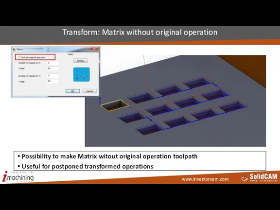
Слайд 27Transform: Matrix without original operation
Possibility to make Matrix witout original operation toolpath
Useful
Transform: Matrix without original operation
Possibility to make Matrix witout original operation toolpath
Useful
Слайд 28Transform: Matrix sorting options
Additional Sorting options in Matrix transformation
Transform: Matrix sorting options
Additional Sorting options in Matrix transformation
Слайд 29Transform: Marking of sorting types affected by optimization
If Optimization of operation loops
Transform: Marking of sorting types affected by optimization
If Optimization of operation loops
Слайд 30Transform: Optimize Matrix Sorting in 4x transformation
If “optimize Matrix sorting“ is
Transform: Optimize Matrix Sorting in 4x transformation
If “optimize Matrix sorting“ is
Слайд 31Transform: Clearance radius for movements between 4th axis positions
Use Tool Z level
Transform: Clearance radius for movements between 4th axis positions
Use Tool Z level
Слайд 32Transform: Access to transform from operation
Possibility to open Transform dialog straight from
Transform: Access to transform from operation
Possibility to open Transform dialog straight from
Слайд 33Transformation of operations from one CoordSys to another
Coordsys where operations should be
Transformation of operations from one CoordSys to another
Coordsys where operations should be
Слайд 34Tooltable
InventorCAM 2015
Tooltable
InventorCAM 2015
Слайд 35Tooltable: Changes in STL holders library
Combine Milling and Turning STL Holders
Tooltable: Changes in STL holders library
Combine Milling and Turning STL Holders
Слайд 36Tooltable: Update operation feeds/spins according to tooltable
Possibilitiy to update feeds and spins
Tooltable: Update operation feeds/spins according to tooltable
Possibilitiy to update feeds and spins
Слайд 37Tooltable: Permanent tool keeps it’s number during import
If tool is marked as
Tooltable: Permanent tool keeps it’s number during import
If tool is marked as
Слайд 38Tooltable: Insert only – add Lead angle
Option to rotate insert, when working
Tooltable: Insert only – add Lead angle
Option to rotate insert, when working
Слайд 39Geometry
InventorCAM 2015
Geometry
InventorCAM 2015
Слайд 40Geometry: Filtering of Pocket Recognition faces by color
Select only faces of specified
Geometry: Filtering of Pocket Recognition faces by color
Select only faces of specified

Слайд 41Geometry: Automatic Curve propagaton with Tangent and Delta-Z
Creating chain geometries has been
Geometry: Automatic Curve propagaton with Tangent and Delta-Z
Creating chain geometries has been
Слайд 42Geometry: Selection of faces by color
Select only faces of specified color in
Geometry: Selection of faces by color
Select only faces of specified color in
Слайд 43Pocket geometry: Option to add Offset
Option to add offset to geometry of
Pocket geometry: Option to add Offset
Option to add offset to geometry of
Слайд 44Slot geometry: Option to add Offset
Option to add offset to geometry of
Slot geometry: Option to add Offset
Option to add offset to geometry of
Слайд 45Drill geometry: Modify option
X and Y shiftings available per hole for Drilling
Drill geometry: Modify option
X and Y shiftings available per hole for Drilling
Слайд 462D Geometry: Changes in wrapped geometry definition
User Interface changes in Wrapped geometry
2D Geometry: Changes in wrapped geometry definition
User Interface changes in Wrapped geometry
Слайд 472D Geometry: Reverse geometry by F5 button
Easy way to reverse geometry –
2D Geometry: Reverse geometry by F5 button
Easy way to reverse geometry –
Слайд 482.5D Mill
InventorCAM 2015
2.5D Mill
InventorCAM 2015
Слайд 49Face milling: Vertical ramping option
New option “Vertical“ for Ramping options in Face
Face milling: Vertical ramping option
New option “Vertical“ for Ramping options in Face
Слайд 50Face milling: Cutting direction optimization
For long geometries that require one way face
Face milling: Cutting direction optimization
For long geometries that require one way face
Слайд 51Face milling: Shifting from center
Shift the single cutting pass by applying %
Face milling: Shifting from center
Shift the single cutting pass by applying %
Слайд 522.5D Mill: Mark by icon changes of geometry offsets
If in an
2.5D Mill: Mark by icon changes of geometry offsets
If in an
Слайд 53Profile: Helical movement improvement
Different start positions: From top to bottom, From
Profile: Helical movement improvement
Different start positions: From top to bottom, From
Слайд 54Profile: Lead in/out on each pass of Clear offset
Use lead in/out on
Profile: Lead in/out on each pass of Clear offset
Use lead in/out on
Слайд 55Pocket: Variable depth
Define depth of pocket per chain => possibility to machine
Pocket: Variable depth
Define depth of pocket per chain => possibility to machine
Слайд 56Pocket: Several wall finish passes
Several finish passes at the same place in
Pocket: Several wall finish passes
Several finish passes at the same place in
Слайд 57Toolbox
InventorCAM 2015
Toolbox
InventorCAM 2015

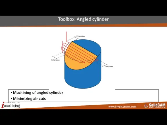
Слайд 58Toolbox: Angled cylinder
Machining of angled cylinder
Minimizing air cuts
Toolbox: Angled cylinder
Machining of angled cylinder
Minimizing air cuts
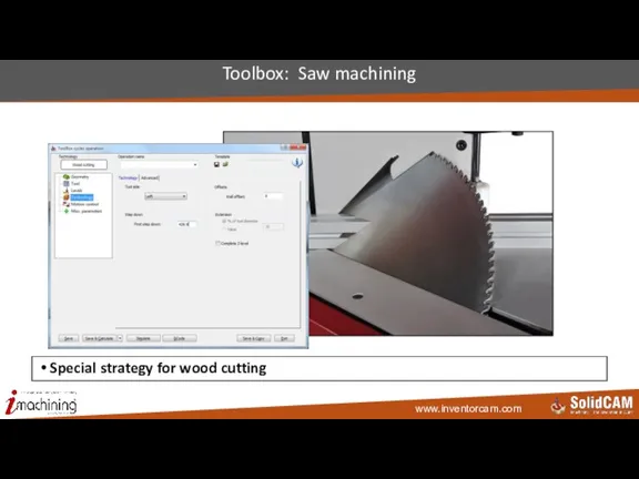
Слайд 59Toolbox: Saw machining
Special strategy for wood cutting
Toolbox: Saw machining
Special strategy for wood cutting
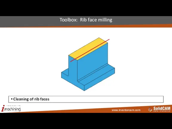
Слайд 60Toolbox: Rib face milling
Cleaning of rib faces
Toolbox: Rib face milling
Cleaning of rib faces
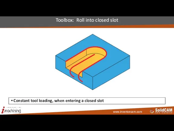
Слайд 61Toolbox: Roll into closed slot
Constant tool loading, when entering a closed slot
Toolbox: Roll into closed slot
Constant tool loading, when entering a closed slot
Слайд 62Toolbox: Roll into open slot
Constant tool loading when entering an open slot
Toolbox: Roll into open slot
Constant tool loading when entering an open slot
Слайд 63Toolbox: Thin wall machining
Special strategy for 2.5D thin wall machining
Toolbox: Thin wall machining
Special strategy for 2.5D thin wall machining
Слайд 64InventorCAM 2015
Automatic Feature Recognition and Machining (AFRM)
InventorCAM 2015
Automatic Feature Recognition and Machining (AFRM)
Слайд 65AFRM: Chamfer recognition and machining
Automatic recognition and machining of edges where it
AFRM: Chamfer recognition and machining
Automatic recognition and machining of edges where it
Слайд 66AFRM: Chamfer recognition and machining
The Automatic recognition of edges is smart and avoids
AFRM: Chamfer recognition and machining
The Automatic recognition of edges is smart and avoids
Слайд 67Automatic Hole Recognition and Machining (AHRM)
InventorCAM 2015
Automatic Hole Recognition and Machining (AHRM)
InventorCAM 2015
Слайд 68AHRM Review
InventorCAM’s AHRM module is designed to automatically:
Classify Shapes and Groups of
AHRM Review
InventorCAM’s AHRM module is designed to automatically:
Classify Shapes and Groups of
Слайд 69AHRM review – Process steps
Step 1: Recognize Holes (Shapes & Groups)
Step 2:
AHRM review – Process steps
Step 1: Recognize Holes (Shapes & Groups)
Step 2:
Слайд 70AHRM review - Step 1: Recognize Holes
Step 1: Recognize Holes
(Shapes
AHRM review - Step 1: Recognize Holes
Step 1: Recognize Holes
(Shapes
Слайд 71AHRM review - Step 2: Machinable segments
Step 2: Convert Holes to Machinable
AHRM review - Step 2: Machinable segments
Step 2: Convert Holes to Machinable
Слайд 72AHRM review - Step 3: Feature Sets
Step 3: Distribute Machinable segments to
AHRM review - Step 3: Feature Sets
Step 3: Distribute Machinable segments to
Слайд 73AHRM review - Step 4: Technology Database Solution
Step 4: Choose technological solution
AHRM review - Step 4: Technology Database Solution
Step 4: Choose technological solution
Слайд 74AHRM review - Step 5: Machining Operations
Step 5: Generate all machining operations
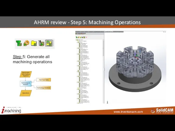
AHRM review - Step 5: Machining Operations
Step 5: Generate all machining operations
Слайд 75AHRM New: Limitless number of DataBase configurations
The user can:
Define as many
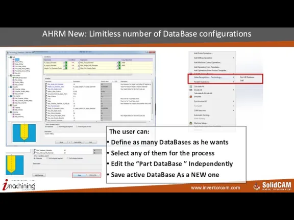
AHRM New: Limitless number of DataBase configurations
The user can:
Define as many
Слайд 76AHRM New: Machinable feature parameters (mf_xxx)
Parameters of machinable features are now available
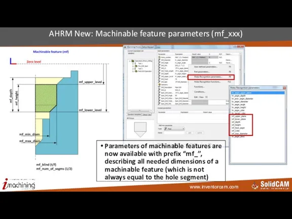
AHRM New: Machinable feature parameters (mf_xxx)
Parameters of machinable features are now available
Слайд 77AHRM New: Conditional Logic Support
Apply different values to parameters, according to user-defined
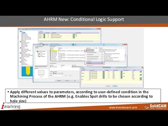
AHRM New: Conditional Logic Support
Apply different values to parameters, according to user-defined
Слайд 78iMachining 2D & 3D
InventorCAM2015
iMachining 2D & 3D
InventorCAM2015
Слайд 79Parallel calculation in iMachining
Speeding up iMachining calculation by using multi cores &
Parallel calculation in iMachining
Speeding up iMachining calculation by using multi cores &
Слайд 80iDatabase Material: Machinability factor
Increase/Decrease Cutting Conditions, based on Machinability of specific material
iDatabase Material: Machinability factor
Increase/Decrease Cutting Conditions, based on Machinability of specific material
Слайд 81iMachining: Constant chip thickness control for arcs
Controls the feed correction for arcs
iMachining: Constant chip thickness control for arcs
Controls the feed correction for arcs
Слайд 82 iMachining 3D: Constant Step up
iMachining 3D option: Constant Set up (as
iMachining 3D: Constant Step up
iMachining 3D option: Constant Set up (as
Слайд 83 iMachining 3D: Prismatic parts machining technology
iMachining 3D technology for Prismatic Part
iMachining 3D: Prismatic parts machining technology
iMachining 3D technology for Prismatic Part
Слайд 84iMachining 3D: Floor offset
Enables you to define a Floor offset that is
iMachining 3D: Floor offset
Enables you to define a Floor offset that is
Слайд 85Show Cutting angle in simulation of iMachining
Showing the cutting angle in iMachining
Show Cutting angle in simulation of iMachining
Showing the cutting angle in iMachining
Слайд 863D Milling
InventorCAM 2015
3D Milling
InventorCAM 2015
Слайд 873D Milling: Reposition options
2 options of tool reposition:
By Rapid move through
3D Milling: Reposition options
2 options of tool reposition:
By Rapid move through
Слайд 88HSR/HSM
InventorCAM 2015
HSR/HSM
InventorCAM 2015
Слайд 89HSR/HSM: Major Speeding up of updated stock calculation
Choose in Settings option of
HSR/HSM: Major Speeding up of updated stock calculation
Choose in Settings option of
Слайд 90HSR/HSM: Selection of non-calculated operations for updated stock
Even if previous operations are
HSR/HSM: Selection of non-calculated operations for updated stock
Even if previous operations are
Слайд 91HSR/HSM: Use updated Stock for linking
Links the passes using dynamic stock(updated stock),
HSR/HSM: Use updated Stock for linking
Links the passes using dynamic stock(updated stock),
Слайд 92HSM: Ramping options added to Constant-Z machining
Ramping options, added to HSM Constant
HSM: Ramping options added to Constant-Z machining
Ramping options, added to HSM Constant
Слайд 93HSR/HSM: Link by area added to HM Roughing
Pockets are machined independently, but
HSR/HSM: Link by area added to HM Roughing
Pockets are machined independently, but
Слайд 94Sim 5X Milling & HSS
InventorCAM 2015
Sim 5X Milling & HSS
InventorCAM 2015
Слайд 95
New Feed Control tab added.
Feed Control enables the user to
New Feed Control tab added.
Feed Control enables the user to
Слайд 96
Surface quality tab: New option of Synchronize points added.
Option is
Surface quality tab: New option of Synchronize points added.
Option is
Слайд 97Sim 5x: Advanced mode button
Only most used options are open in the
Sim 5x: Advanced mode button
Only most used options are open in the
Слайд 98
In Tool axis direction/Tilted through lines: New option of Always closest
In Tool axis direction/Tilted through lines: New option of Always closest
Слайд 99
In Tool axis direction: New option of Tilted relative to contact
In Tool axis direction: New option of Tilted relative to contact
Слайд 100New Multiaxis Roughing operation is added for Roughing of parts, that need
New Multiaxis Roughing operation is added for Roughing of parts, that need
Слайд 101New operation: MultiAxis Roughing
This operation creates a multiaxis tool path that can
New operation: MultiAxis Roughing
This operation creates a multiaxis tool path that can
Слайд 102Contour 5x machining: Enforce cutting direction
Direction is set according to direction of
Contour 5x machining: Enforce cutting direction
Direction is set according to direction of
Слайд 103Contour 5x Machining: Tilt away from line
Tilt away from line defines the
Contour 5x Machining: Tilt away from line
Tilt away from line defines the
Слайд 104Multiblade Machining: Machine angle limits – Min & Max
Machine angle limit is
Multiblade Machining: Machine angle limits – Min & Max
Machine angle limit is
Слайд 105Multiblade Machining: Entry & Exit Safety distance
Safety distance is divided into two
Multiblade Machining: Entry & Exit Safety distance
Safety distance is divided into two
Слайд 106Multiblade Machining: Additional Clearance type - Conical
A new Tool Clearance type, Conical,
Multiblade Machining: Additional Clearance type - Conical
A new Tool Clearance type, Conical,
Слайд 107
Levels page: New Levels section is added to enable entry and
Levels page: New Levels section is added to enable entry and
Слайд 108
Tool axis control page: Limits section has enhancements.
Multiblade Machining: Tool Axis
Tool axis control page: Limits section has enhancements.
Multiblade Machining: Tool Axis
Слайд 109Multiblade Machining: Plunge arc for link between slices or layers
Option to
Multiblade Machining: Plunge arc for link between slices or layers
Option to
Слайд 110
Tool path parameters page/Technology/ Options of Rest material, First slice, and
Tool path parameters page/Technology/ Options of Rest material, First slice, and
Слайд 111
Roughing and More is renamed as Stock and Transformation.
Multiblade Machining: GUI
Roughing and More is renamed as Stock and Transformation.
Multiblade Machining: GUI
Слайд 112Port Machining: Additional Clearance type - Conical
A new Tool Clearance type,
Port Machining: Additional Clearance type - Conical
A new Tool Clearance type,
Слайд 113Port Machining: Tool axis control page
Tool axis control page added in
Port Machining: Tool axis control page
Tool axis control page added in
Слайд 114
Tool axis control: Minimize tilting is added.
Port Machining: Tool Axis Control
Tool axis control: Minimize tilting is added.
Port Machining: Tool Axis Control
Слайд 115SWARF Machining: Surface normal defines machining side
Side of machining is determined according
SWARF Machining: Surface normal defines machining side
Side of machining is determined according
Слайд 116SWARF Machining: New Avoid gouge strategy and new Layout for gouge page
New
SWARF Machining: New Avoid gouge strategy and new Layout for gouge page
New
Слайд 117SWARF Machining: Feed control
More flexible control over cutting and retract speeds
Possibility to
SWARF Machining: Feed control
More flexible control over cutting and retract speeds
Possibility to
Слайд 118SWARF Machining: Adding extensions to toolpath
New option to add extensions to the
SWARF Machining: Adding extensions to toolpath
New option to add extensions to the
Слайд 119SWARF Machining: Degouging strategy
New options to avoid gouges with drive surface
Degouge option
SWARF Machining: Degouging strategy
New options to avoid gouges with drive surface
Degouge option
Слайд 120SWARF Machining: Rotate & Translate
Rotate & Translate option is available for SWARF
SWARF Machining: Rotate & Translate
Rotate & Translate option is available for SWARF
Слайд 121SWARF/MultiBlade/Port/MultiAxis Roughing: Custom triangulation
Provide more control over surface triangulation
Custom triangulation check
SWARF/MultiBlade/Port/MultiAxis Roughing: Custom triangulation
Provide more control over surface triangulation
Custom triangulation check
Слайд 122Multiaxis Drilling: retract tool along tool axis
Avoid collisions by preventing sudden tool
Multiaxis Drilling: retract tool along tool axis
Avoid collisions by preventing sudden tool
Слайд 123
The Multiaxis Drilling Technology page has a new option: Use cycle.
Multiaxis
The Multiaxis Drilling Technology page has a new option: Use cycle.
Multiaxis
Слайд 124
New Technology of Autotilt is added.
Convert HSM to Sim 5-Axis Milling:
New Technology of Autotilt is added.
Convert HSM to Sim 5-Axis Milling:
Слайд 125
Tool axis control page has new options when Autotilt is selected
Tool axis control page has new options when Autotilt is selected
Слайд 126
Source operation page has the new option of Workpiece clearance.
Convert HSM
Source operation page has the new option of Workpiece clearance.
Convert HSM
Слайд 127
Stock definition: New option of Trim only full contours is added.
Roughing
Stock definition: New option of Trim only full contours is added.
Roughing
Слайд 128
2D Boundary curves content is placed inside Geometry page.
GUI Changes -
2D Boundary curves content is placed inside Geometry page.
GUI Changes -
Слайд 129
Parameters divided into two tabs: Regular (most used) and Advanced.
GUI
Parameters divided into two tabs: Regular (most used) and Advanced.
GUI
Слайд 130
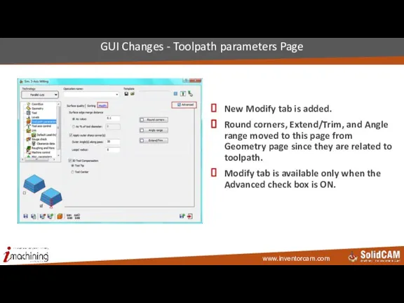
New Modify tab is added.
Round corners, Extend/Trim, and Angle range
New Modify tab is added.
Round corners, Extend/Trim, and Angle range
Слайд 131
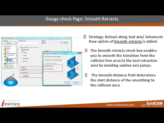
Strategy: Retract along tool axis/ Advanced: New option of Smooth retracts
Strategy: Retract along tool axis/ Advanced: New option of Smooth retracts
Слайд 132
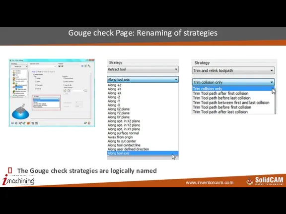
The Gouge check strategies are logically named
Gouge check Page: Renaming of
The Gouge check strategies are logically named
Gouge check Page: Renaming of
Слайд 133
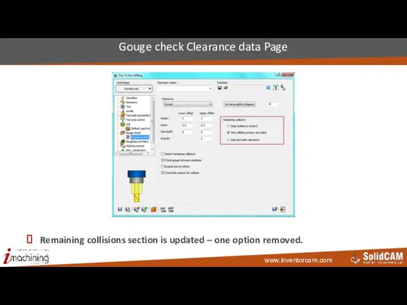
Remaining collisions section is updated – one option removed.
Gouge check Clearance
Remaining collisions section is updated – one option removed.
Gouge check Clearance
Слайд 134Turning
InventorCAM 2015
Turning
InventorCAM 2015
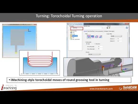
Слайд 135Turning: Torochoidal Turning operation
iMachining-style torochoidal moves of round grooving tool in turning
Turning: Torochoidal Turning operation
iMachining-style torochoidal moves of round grooving tool in turning
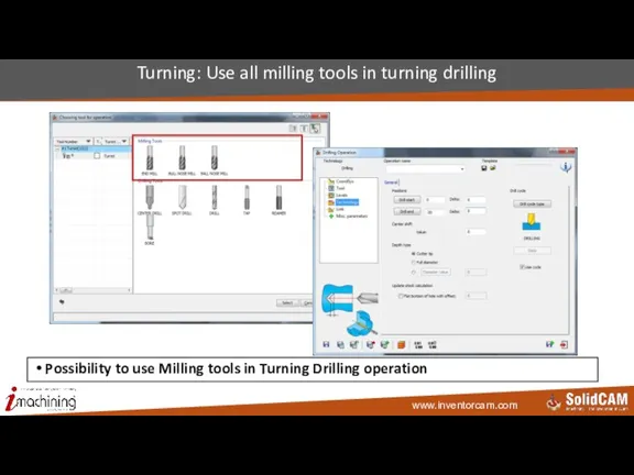
Слайд 136Turning: Use all milling tools in turning drilling
Possibility to use Milling tools
Turning: Use all milling tools in turning drilling
Possibility to use Milling tools
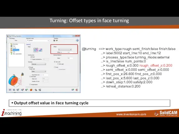
Слайд 137Turning: Offset types in face turning
Output offset value in Face turning cycle
@turning
Turning: Offset types in face turning
Output offset value in Face turning cycle
@turning
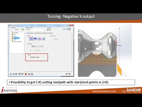
Слайд 138Turning: Negative X output
Possibility to get (-X) cutting toolpath with start/end points
Turning: Negative X output
Possibility to get (-X) cutting toolpath with start/end points
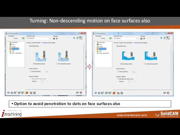
Слайд 139Turning: Non-descending motion on face surfaces also
Option to avoid penetration to slots
Turning: Non-descending motion on face surfaces also
Option to avoid penetration to slots
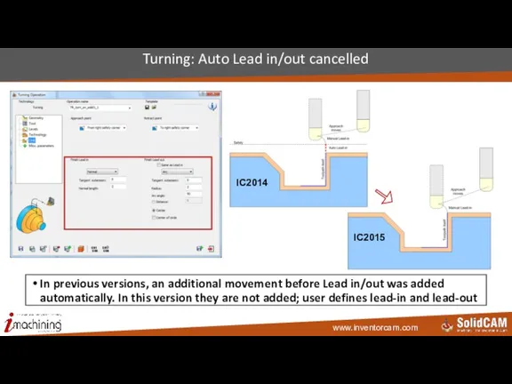
Слайд 140Turning: Auto Lead in/out cancelled
In previous versions, an additional movement before
Turning: Auto Lead in/out cancelled
In previous versions, an additional movement before
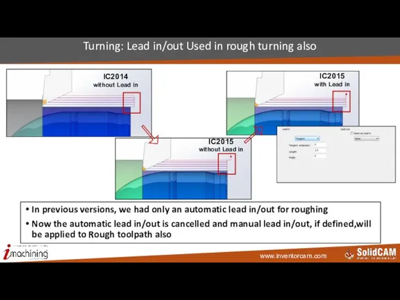
Слайд 141Turning: Lead in/out Used in rough turning also
In previous versions, we
Turning: Lead in/out Used in rough turning also
In previous versions, we
Слайд 142Turning: Split long lines of turning toolpath
Split long lines of turning toolpath
Turning: Split long lines of turning toolpath
Split long lines of turning toolpath
Слайд 143Mill-Turn
InventorCAM 2015
Mill-Turn
InventorCAM 2015
Слайд 144Machine ID: Machine orientation
World CoordSys is always with Z vertically UP
Machine orientation
Machine ID: Machine orientation
World CoordSys is always with Z vertically UP
Machine orientation
Слайд 145Turret: New style of station creation in VMID
Easy way to create multiple
Turret: New style of station creation in VMID
Easy way to create multiple
Слайд 146MCO: Calculate all related operations when MCO changes
Automatic calculation of changed MCO‘s
MCO: Calculate all related operations when MCO changes
Automatic calculation of changed MCO‘s
Слайд 147MCO: Move Part by turret or any other device
Possibility to move the
MCO: Move Part by turret or any other device
Possibility to move the
Слайд 148Tooltable: new mounting interface
New tool mounting interface – based on station and
Tooltable: new mounting interface
New tool mounting interface – based on station and
Слайд 149Tooltable: Show station name
Show station name in the List of stations in
Tooltable: Show station name
Show station name in the List of stations in
Слайд 150Update material boundary (for mill-turn)
Take into account HSR/HSM operations when updating stock
Update material boundary (for mill-turn)
Take into account HSR/HSM operations when updating stock
Слайд 151Definition of Cross Control
By default – cross control is always turned on
*.VMID
Definition of Cross Control
By default – cross control is always turned on
*.VMID
Слайд 152Channels definition in VMID
Custom channels definition
Definition of channels by sub-machines, not
Channels definition in VMID
Custom channels definition
Definition of channels by sub-machines, not
Слайд 153Full support of Mazak Mill Turn machines
Opposite spindle
Rotary turret
Simultaneous 5 axes
Balanced turning
Part
Full support of Mazak Mill Turn machines
Opposite spindle
Rotary turret
Simultaneous 5 axes
Balanced turning
Part
Слайд 154Full support of Fanuc Mill Turn machines
Opposite spindle
Rotary turret with milling functionality
Simultaneous
Full support of Fanuc Mill Turn machines
Opposite spindle
Rotary turret with milling functionality
Simultaneous
Слайд 155Support of machines with combined turrets
Opposite spindle
Rotary turret as B-axis
Linear turrets
Simultaneous 5
Support of machines with combined turrets
Opposite spindle
Rotary turret as B-axis
Linear turrets
Simultaneous 5
Слайд 156Support of Multi-station Combined-turrets Mill-Turn machines
Two spindles, Each turret is a combined
Support of Multi-station Combined-turrets Mill-Turn machines
Two spindles, Each turret is a combined
Слайд 157Support of Willemin-style Mill-Turn machines
Willemin-style: Two spindles, B-axis, Additional devices (Clamps and
Support of Willemin-style Mill-Turn machines
Willemin-style: Two spindles, B-axis, Additional devices (Clamps and
Слайд 158Support of Chiron-style Mill-Turn machines
Chiron-style: Main spindle, Rotary Turret, B-axis, Tilting of
Support of Chiron-style Mill-Turn machines
Chiron-style: Main spindle, Rotary Turret, B-axis, Tilting of
Слайд 159Support of Index-style Mill-Turn machines
Index-style: Two spindles, Each turret is a combined
Support of Index-style Mill-Turn machines
Index-style: Two spindles, Each turret is a combined
Слайд 160Simulation
InventorCAM2015
Simulation
InventorCAM2015
Слайд 161Simulation: Show STL holders in simulation
Show STL holders in simulation and in
Simulation: Show STL holders in simulation
Show STL holders in simulation and in
Слайд 162Simulation: Show current CoordSys in SolidVerify simulation
Show current CoordSys in SolidVerify simulation
Useful
Simulation: Show current CoordSys in SolidVerify simulation
Show current CoordSys in SolidVerify simulation
Useful
Слайд 163Tool Libraries integrations
InventorCAM 2015
Tool Libraries integrations
InventorCAM 2015
Слайд 164Tool Libraries
Online / Offline Databases from Tool Manufacturer
Offering 2D/3D CAD Models with
Tool Libraries
Online / Offline Databases from Tool Manufacturer
Offering 2D/3D CAD Models with
Слайд 165ISCAR Tool Advisor (ITA)
Online Catalog with assistance to guide users to the
ISCAR Tool Advisor (ITA)
Online Catalog with assistance to guide users to the
Слайд 166Integration with ISCAR Tool Advisor (ITA)
At the Import Option of the Tool
Integration with ISCAR Tool Advisor (ITA)
At the Import Option of the Tool
Слайд 167Carmex
Carmex is specialized in the Production of Threading Tools for Turning and
Carmex
Carmex is specialized in the Production of Threading Tools for Turning and
Слайд 168Integration with Carmex Tool Library
( Carmex software should be installed )
Integration at
Integration with Carmex Tool Library
( Carmex software should be installed )
Integration at
Слайд 169Vardex
Vardex is a Product Line from Vargus for Threading Tools
http://www.vargus.de/
Vardex
Vardex is a Product Line from Vargus for Threading Tools
http://www.vargus.de/
Слайд 170 Integration with Vardex Tool Library
( Vardex software should be installed )
Integration
Integration with Vardex Tool Library
( Vardex software should be installed )
Integration
Слайд 171Tool Management Softwares Integration
InventorCAM 2015
Tool Management Softwares Integration
InventorCAM 2015
Слайд 172Tool Data Management Softwares
Software to manage the overall information of Tools
WinTool
TDM
Tool Data Management Softwares
Software to manage the overall information of Tools
WinTool
TDM
Слайд 173Tool Data Management (TDM) Software
Cutting Conditions
2D / 3D CAD Model
Production Information
Tool Presetting
Tool Data Management (TDM) Software
Cutting Conditions
2D / 3D CAD Model
Production Information
Tool Presetting
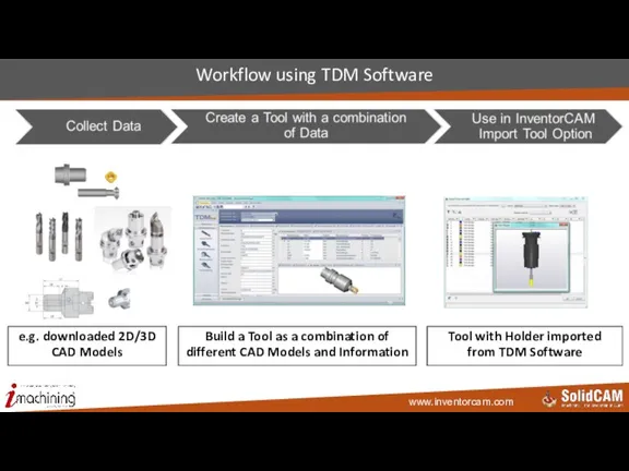
Слайд 174Workflow using TDM Software
e.g. downloaded 2D/3D CAD Models
Tool with Holder imported
Workflow using TDM Software
e.g. downloaded 2D/3D CAD Models
Tool with Holder imported
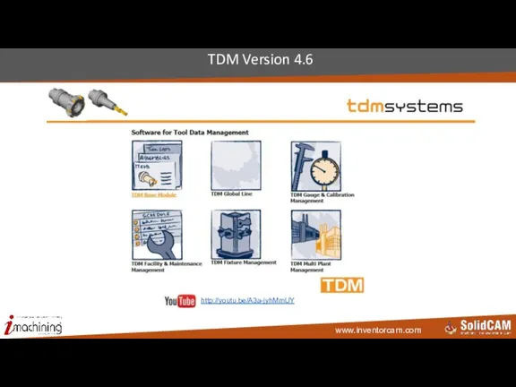
Слайд 175TDM Version 4.6
http://youtu.be/A3a-jyhMmUY
TDM Version 4.6
http://youtu.be/A3a-jyhMmUY
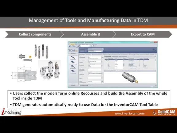
Слайд 176Management of Tools and Manufacturing Data in TDM
Users collect the models form
Management of Tools and Manufacturing Data in TDM
Users collect the models form
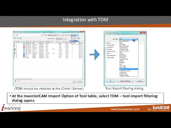
Слайд 177Integration with TDM
(TDM should be installed at the Client / Server)
Tool Import
Integration with TDM
(TDM should be installed at the Client / Server)
Tool Import
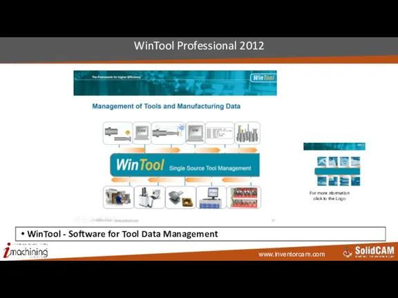
Слайд 178WinTool Professional 2012
For more nformation click to the Logo
WinTool - Software for
WinTool Professional 2012
For more nformation click to the Logo
WinTool - Software for
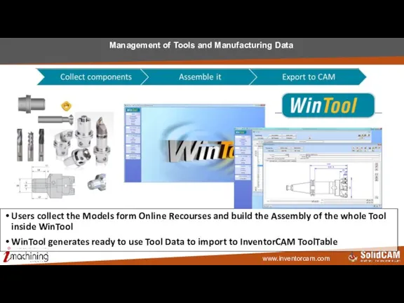
Слайд 179Management of Tools and Manufacturing Data
Users collect the Models form Online Recourses
Management of Tools and Manufacturing Data
Users collect the Models form Online Recourses
 Циклические алгоритмы
 Пять дней без социальных сетей
 Подключение к удаленному рабочему столу, отладка параметров
 Software. Operating system
 SQL-01-3 (Введение в SQL)
 Мой супер сайт
 Переменка. Разработка программного продукта в среде Delphi 7
 База данных. Определение
 Примеры решения задач
 Циклы по переменной. Программирование на языке Python
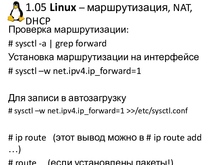 Linux – маршрутизация, NAT, DHCP
 Яндекс.Учебник. Комбинация классического содержания и новых методов обучения
 Построение автоматизированных информационных систем
 Понятие алгоритма. Лабораторные занятия по Информатике
 Глобальные компьютерные сети
 Работа со строками. Класс String
 Искусственные и естественные источники информации
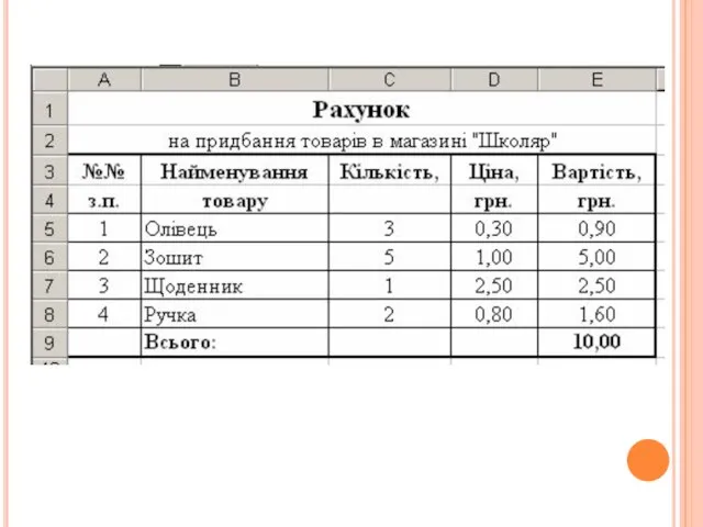 Електронна таблиця
 Создаем аудогид
 Программирование линейных алгоритмов
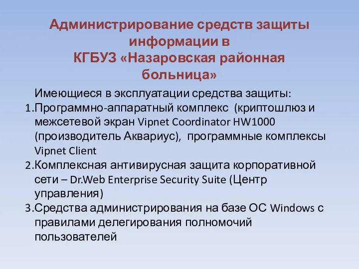 Администрирование средств защиты информации в КГБУЗ Назаровская районная больница
 Клуба журналистики ПМК Альфа
 Имаджинариум с легким уклоном в автомобильную тематику. Техническое задание
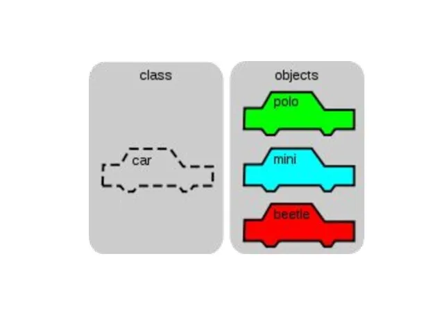 Объектноориентированное программирование. Наследование
 Системы распределенного реестра
 Основы языка JavaScript
 Внедрение и развитие автоматизированного тестирования Siebel CRM
 Презентация на тему Информация. Компьютер. Информатика.